AMAZON multi-meters discounts AMAZON oscilloscope discounts
The preceding sections dealt with most of the early steps in the design process, such as the choice of thermal design strategy (Section 4), the choice of siting (Section 3), and the choice of the components and initial sizing of envelopes (Sections 7 and 8). Section 5 dealt with strategies and equipment for indoor air quality. Sections 9 and 10 carry the design process into the specifics of mechanical systems and equipment for heating and cooling.
There are various ways to organize this large collection of components and systems. The next two Sections are organized as follows:
Section 9:
1. A review of the relative thermal role of building envelopes versus their internal heating/cooling equipment
2. A look at the heating/cooling system design process begun by the architect and completed by the engineer
3. Equipment location and sizing for smaller buildings (one or a few thermal zones)
4. Controls for smaller buildings
5. Refrigeration cycles
6. Cooling-only systems
7. Heating-only systems
8. Heating and cooling systems
9. Psychrometry and refrigeration Section 10:
10. The basics of the process by which mechanical systems are integrated into building design
11. The four generic HVAC system types for large buildings
12. Larger, centralized HVAC equipment
13. Air distribution considerations within spaces
14-17. Details of the four generic HVAC systems
18, 19. Large-scale system opportunities
Items 1, 2, and 10 are a more theoretical introduction to systems and equipment; hence, rather than reading the Section in order, you could read those items first, then go on to the component-and-equipment sections.
1. REVIEW OF THE NEED FOR MECHANICAL EQUIPMENT
One of the most basic functions of buildings is to provide shelter from weather. In a carefully designed building, the roofs, walls, windows, and interior surfaces alone can maintain comfortable interior temperatures for most of the year in most North American climates. With appropriate scheduling, the most uncomfortable hours within buildings can often be avoided; for example, the siesta avoids the hottest afternoon hours within stores and office buildings. Several aspects of comfort and climate, however, pose difficult challenges for ordinary building forms and materials.
A building surface influences comfort primarily through its surface temperature; secondarily, it slowly changes air temperature (as when cool air moves across a warm surface). Important as these two determinants of comfort are, they sometimes are not sufficient by themselves. Especially in cooling situations, air motion and RH are significant comfort determinants; and for many indoor activities, air quality becomes an important issue in both heating and cooling.
Building form can work with climate to pro duce air motion for cooling, although the faster air speeds that extend the human comfort zone above 83ºF (28ºC) may be difficult to provide without mechanical assistance. Relative humidity is still controlled by mechanical (or chemical) means.
Building form and materials may be able to keep spaces surprisingly cool, but without dehumidification, surfaces in many North American summer climates can become clammy and covered with mold.
It is difficult to filter air without a fan to force the air through the filtering medium. Electrostatic filtering, of course, is done within mechanical equipment.
Thus, whereas the desired air and surface temperatures can often be achieved by passive means (a combination of building form, surface material, and occasional user response), the comfort determinants of air motion, RH, and air quality often require mechanical devices. As the control of air properties-motion, moisture, particulate content-becomes more critical to comfort, the designer becomes more likely to respond with a sealed building, excluding outdoor air except through carefully controlled mechanical equipment intakes. In the recent past, this exclusion of outdoor air has often been accompanied by the exclusion of daylight, of view, of solar heat on cold days-in sum, by a general rejection of all aspects of the exterior environment. As designers come to terms with the role of mechanical equipment, they should also clarify the role of these devices in relation to the climate: Are they occasional modifiers, permanent interpreters, or permanent excluders of the outdoors?
2. HEATING, VENTILATING, AND AIR CONDITIONING (HVAC): TYPICAL DESIGN PROCESSES
HVAC systems usually involve a minimum of three design stages. In the preliminary design phase, the most general combinations of comfort needs and climate characteristics are considered:
Activity comfort needs are listed.
An activity schedule is developed.
Site energy resources are analyzed.
Climate design strategies are listed.
Building form alternatives are considered.
Combinations of passive and active systems are considered.
One or several alternatives are sized by general design guidelines.
This level of analysis covers the process discussed in Section 1 and Sections 8.1 to 8.6. For smaller buildings, this analysis is often done by the architect alone. For innovative or unusual systems in smaller buildings, and especially for larger, multiple-zone buildings, consultants such as engineers and landscape architects often are included. The team approach is particularly valuable in assessing the strengths of various design alternatives. The architect and the consultants have very different perspectives, and when mutual goals can be clearly agreed on early in the design process, these perspectives are not only mutually supporting but can produce striking innovations whose benefits extend far beyond services to the clients of a particular building. By setting an example, the team can make available better environments for less energy for hundreds of subsequent buildings. With inspired teamwork, the distribution of HVAC services can enhance building form, as many examples in this Section show.
By the time the design development phase is reached, one of the design alternatives has probably been chosen as the most promising combination of aesthetic, social, and technical solutions for the pro gram. The consulting engineer (or architect, on a smaller job) is furnished with the latest set of drawings and the program. Typically, the architectural or mechanical engineer then:
I. Establishes design conditions.
A. By activity, lists the range of acceptable air and surface temperatures, air motions, relative humidities, lighting levels, and back ground noise levels.
B. Establishes the schedule of operations.
II. Determines the HVAC zones, considering:
A. Activities.
B. Schedule.
C. Orientation.
D. Internal heat gains.
III. Estimates the thermal loads on each zone:
A. For worst winter conditions.
B. For worst summer conditions.
C. For the average condition or conditions that represent the great majority of the building's operating hours.
D. Frequently, an estimate of annual energy consumption is made.
IV. Selects the HVAC systems. Often, several systems will be used within one large building because orientation, activity, or scheduling differences may dictate different mechanical solutions. Especially common is one system for the all-interior zones of large buildings and another system for the perimeter zones.
V. Identifies the HVAC components and their locations.
A. Mechanical rooms.
B. Distribution trees-vertical chases, horizontal runs.
C. Typical in-space components, such as under-window fan-coil units, air grilles, and so on.
VI. Sizes the components.
VII. Lays out the system. At this stage, conflicts with other systems (structure, plumbing, fire safety, circulation, etc.) are most likely to become evident. Because insufficient vertical clearance is one of the most common building coordination problems with HVAC systems (especially all-air systems-see Sections 10.2 and 10.5), the layouts must include sections as well as plans. Opportunities for integration with other systems also become more apparent at this stage: air ducts can also help distribute daylighting, act as sunshading devices, or fulfill other functions.
After the architect and the other consultants hold conferences in which HVAC system layout drawings are compared to those for other primary systems (structure, plumbing, electrical, etc.), design finalizing occurs. At this final stage, the HVAC sys tem designer verifies the match between the loads on each component and the component's capacity to meet the load. Final layout drawings then are completed.
3. EQUIPMENT LOCATION AND SERVICE DISTRIBUTION
This Section considers smaller buildings with one or a few thermal zones. For larger buildings, turn now to Section 10.
Smaller buildings are typically skin load dominated: that is, for them, the climate dictates whether heating or cooling is the major concern. In some climates, only heating systems are needed; the building can "keep itself cool" during hot weather without mechanical assistance. In other climates, only cooling is needed. In still others, both heating and cooling are required.
(a) Central or Local?
A skin-load-dominated building may have such differing but simultaneous needs that a room by-room solution ("local") for heating, ventilating, and cooling is desirable. Consider a building with both north- and south-facing spaces on a cold, sunny winter day; one side gets ample solar heat, while the other side needs additional heat.
The advantage of local systems is their ability to respond quickly to individual rooms' needs.
The central system also has advantages: the equipment is contained within its own space rather than taking up space within each room, and maintenance can be carried out without disrupting activities within those rooms.
(b) Central Heating or Cooling Equipment
In the early design stages, determining an approximate size for the largest equipment is sometimes useful. Once the heating or cooling capacities are known, manufacturers' catalogs can be consulted for the dimensions of the heating and cooling equipment.
The critical decision in sizing the heating equipment is the design temperature: what is the lowest reasonable outdoor temperature for which a heating device should be sized, if the desired interior temperature is to be maintained? These winter design temperatures are listed in Section B. When this is known, the next step is design delta_t = inside temperature - outside design temperature
In Section 8.4, the criteria for Btu/DD ft^2 were listed in Table 8.3. To convert to the required capacity of a building's heating equipment, calculate
Btu/DD ft^2/ [24 h] ft^2 floor area
= Btu/h heating capacity
Note: For passively solar-heated buildings, the backup heating unit is sometimes sized for the heat loss of the entire envelope and sometimes for the envelope minus the solar wall, just as the criteria were defined in Table 8.3. Similarly, buildings with reliable internal gains (lights, equipment, people, etc.) are sometimes designed with smaller heating units because internal gains supply a constant portion of the space-heating needs. For a more complete discussion, see Section 8.8.) The sizing of cooling (mechanical refrigeration) units is not so straightforward, as was evident when detailed hourly heat gain procedures were presented (Sections 8.11 and 8.13). However, a very approximate early estimate can be obtained from the estimated hourly gains in Table F.3. (Warning: This estimate is likely to be lower than that obtained using the peak heat gain hour, for which cooling equipment is often sized.)
sensible Btu/h cooling capacity = [approx. heat gain (Btu/h ft^2)][floor area (ft^2)]
Another common unit used for sizing mechanical refrigeration is tons of cooling capacity, 1 ton being equivalent to the useful cooling effect of a ton of ice, or 12,000 Btu/h (3516 W).
Therefore, the required capacity in tons is
heat gain, Btu/h / 12,000 = tons of cooling
With this information about needed Btu/h (or watts), equipment is then selected; physical size and service access areas are specified in catalogs. For a more general floor area estimate, see the sizing nomographs in Tables 10.3 and 10.4. Even more generally, equipment size may be estimated using these guidelines:
For ordinary equipment: 500 ft 2/ton (46.5 m^2/ton) High-efficiency chillers: 1000 ft^2/ton (93 m^2/ton)
(c) Distribution Trees
Central heating/cooling systems produce heating and cooling in one place, then distribute these effects to other building spaces according to their respective needs. The distribution tree is the means for delivering heating and cooling: the "roots" are the machines that provide heat and cold, the "trunk" is the main duct or pipe from the mechanical equipment to the zone to be served, and the "branches" are the many smaller ducts or pipes that lead to individual spaces.
For now, the questions to be answered about distribution trees for buildings are: How many? What kind? Where? A building can have one giant distribution tree, several medium-sized trees, or an orchard of much smaller trees. At one extreme, a large mechanical room is the scene of all heating and cooling production; leading from this room is a very large trunk duct with perhaps hundreds of branches. At the other extreme, each zone has its own mechanical equipment (such as a rooftop heat pump), with short trunks and relatively few branches on each tree.
What kind of distribution tree? Most simply, air (ducts) or water (pipes). Air distribution trees are bulky and therefore likely to have major visual impacts unless they are concealed above ceilings, below floors, or within vertical chases. Water distribution trees consume much less space (a given volume of water carries vastly more heat than does the same volume of air at the same tempera ture) and can be easily integrated within structural members such as columns. Both air and water trees can be sources of noise.
Where does the distribution tree fit in?
On the exterior, it can lend a three-dimensional organizational structure to a façade. Exterior trees can take up a smaller amount of rentable floor space but require expensive cladding and are subject to considerable heat losses and gains, which could increase energy usage. Interior trees are often combined with other continuous vertical spaces, such as elevator shafts and stairways. If the choice is an exterior distribution tree, its potential contribution to façade performance should be considered. For example, the distribution tree might act as a sun shade or as a light reflector.
To carry the tree analogy to its logical conclusion, consider the "leaves," the points of interchange between the piped or ducted heating or cooling and the spaces served. One example is a large, bulky device such as a fan-coil unit on the exterior wall below windows. In contrast, a perforated ceiling system with thousands of small holes acting as a widely spread grille is essentially invisible.
4. CONTROLS FOR SMALLER BUILDING SYSTEMS
In the past, when buildings had mechanical equipment for heating only, thermostats were simple on off devices; when they dropped below a setpoint, the heat was turned on. With the advent of mechanical cooling and then concerns about energy conservation, thermostats added a deadband separating heating need temperature from cooling need temperature, and automatic setback provisions that allow buildings to change internal temperature between occupied and unoccupied hours. ANSI/ ASHRAE Standard 90.2, Energy-Efficient Design of Low-Rise Residential Buildings, calls for thermostats capable of being set from 55ºF to 85ºF (13ºC to 29ºC) as well as an adjustable deadband, the range of which includes a setting of 10Fº (5.6Cº).
Building management systems (BMS) are now capable of regulating far more than temperature.
They are capable of remote control, allowing systems to be activated in advance of the occupants' arrival; this is particularly useful for weekend and vacation homes, where heating/cooling and domestic hot water systems, if left on, could waste much energy during unoccupied periods. Door and window locks, security cameras, lighting, and appliances are potential partners in a comprehensive control system.
Future developments include neural networks, where automation systems are capable of learning while being used. They thus predict usage patterns, adjusting in advance without needing specific commands from occupants. When the building use pat tern is highly predictable, as with many retail and commercial occupancies, these self-programming systems should learn very quickly how to anticipate needs while conserving energy.
In residences, usage patterns are likely more varied and less predictable. Experiments at the University of Colorado have revealed that even here, patterns may be more predictable than was first thought; for details, see Mozer (1998). The Adaptive Control of Home Environments (ACHE) system has two objectives: to anticipate inhabitants' needs and to save energy. Lighting, air tempera ture, ventilating, and water heating are controlled so that just enough energy, just when needed, is provided. Lights will be set to the minimum required, hot water maintained at the minimum temperature to meet demands, only occupied rooms will be kept at an optimum comfortable temperature, and so on.
The control framework compares energy costs to "misery" costs. Minimum settings and their time patterns are developed as the building is occupied over time. Whenever a preset minimum is over ruled by the occupant, the system learns and readjusts accordingly; however, it occasionally tests lower minimum settings to be sure that energy conservation is not being unduly sacrificed to past desires.
5. REFRIGERATION CYCLES
Unlike the slow, diffuse heat transfer processes that characterize passive heating and cooling approaches, mechanical equipment can rap idly concentrate heating or cooling on demand.
The refrigeration cycle is a particularly useful mechanical process in heating as well as cooling applications. The two types of heat transfer process commonly used in mechanical equipment for buildings are the compressive and the absorption refrigeration cycles. (Equipment that utilizes these cycles is discussed in the remainder of this Section and in Section 10.)
(a) Compressive Refrigeration
As shown in FIG. 1, the compressive refrigeration cycle is a scheme for transferring heat from one circulated water system (chilled water) to another (condenser water). This is done by the liquefaction and evaporation of a refrigerant, during which processes it gives off and takes on heat, respectively.
The heat it gives off must be disposed of (except in the heat pump), but the heat it acquires is drawn out of the circulated water known as the chilled water, which is the medium for subsequent cooling processes.
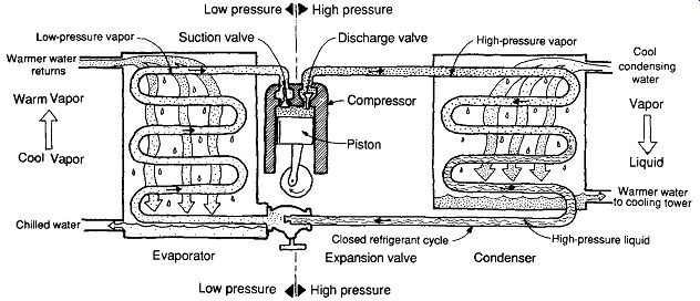
FIG. 1 Schematic arrangement of the compressive refrigeration cycle, providing
chilled water for a building cooling system.
Refrigerants are gases at normal temperatures and pressures, and must be compressed and liquefied to be of service later as heat absorbers.
To be liquefied (see FIG. 1), the refrigerant must first be compressed to a high-pressure vapor; then, by means of cool water, latent heat is extracted from the refrigerant, which condenses it to a liquid. This high-pressure liquid is a potential heat absorber because, when it is released through an expansion valve, it springs back mechanically to its gaseous form. In this change of state, it must take on latent heat by drawing heat out of the circulated water of the chilled water system.
It may be said that the refrigeration cycle pumps the heat out of the chilled water system into the condenser water system. Indeed, by special (reverse cycle) arrangements of the water systems, a heat pump is the result. (The compressive refrigeration cycle can be used to transfer heat between almost any media; whereas FIG. 1 illustrates a water-water cycle, FIG. 38 shows the heat pump in both air-air and water-air applications.) The piston-type compressor in FIG. 1 can instead be one of several other types: rotary, scroll, or screw compressors, each with characteristics suitable to particular applications. See Section 10 for further discussion.
(b) Alternative Refrigerants
Unfortunately, the most commonly used refrigerants of the early 1990s are a threat to our atmosphere, because they can escape from the equipment as chlorofluorocarbon (CFC) gases. The threats are stratospheric ozone depletion and global warming.
A related global warming threat is the CO2 released from the production of electricity that powers chillers and other refrigeration machines. There is a potential conflict if lower-threat refrigerants are less efficient and therefore produce higher energy consumption. This conflict assumes continued power generation by fossil fuels; if photovoltaics (PV) are used to power these cooling devices, this aspect of the threat to global warming disappears.
Production of CFC refrigerants was banned in the United States by the mid-1990s. (A black market quickly developed for widely used CFC refrigerants such as Freon.) Fears that replacement refrigerants would be less efficient have largely disappeared; combinations of better chillers and new refrigerants produce energy savings.
Considerable efforts are under way both to reduce the likelihood of escaping refrigerant and to develop more efficient non-CFC refrigerants.
The first alternative was hydrochlorofluorocarbon (HCFC) refrigerants-still a threat to our atmosphere, but better than CFC. HCFC still contains chlorine, a major influence on ozone depletion.
Thus, HCFCs themselves are due to be phased out in the first decades after 2000. A longer-term replacement is hydrofluorocarbons (HFCs); even this improvement still threatens our atmosphere. Yet another possibility is natural hydrocarbons (HC). In general, comparing these two alternatives, HFCs have higher global warming potential and long atmospheric lifetimes, but they have low toxicity and are nonflammable. HCs have negligible global warming potential and short atmospheric lifetimes, but are flammable and explosive.
One alternative is ammonia, used in the early years of compressive refrigeration but discontinued because of its acute toxicity and (relative to CFCs) its flammability. It is now returning in some absorption cooling cycles. Ammonia does have the advantage of having a strong and unmistakable odor; it warns of its leakage, unlike the other refrigerants. Use of ammonia will require regular maintenance, good ventilation, and good access/ escape routes. It will encourage systems that keep the refrigerant loop within controlled spaces such as mechanical rooms.
The search for the ideal refrigerant continues and may never end. This is another area in which rapid developments may be expected in the near future. For a comprehensive review of refrigerants, see Calm (1994).
(c) Absorption Refrigeration Cycle
This process is illustrated in FIG. 2. No CFCs or HCFCs are used here; the process uses distilled water as the refrigerant and lithium bromide (salt solution) as the absorber. In order to remove heat from chilled water, this cycle uses still more heat in regenerating the salt solution. Typically, it is less efficient than the simple compressive cycle and needs about twice the capacity for rejecting heat. However, the heat for salt solution regeneration may be provided by solar energy or by relatively high-temperature waste heat from another source, such as steam or hot water, as from a fuel cell or industrial process. Because the high-grade energy (electricity) needed to run a compressor is replaced by the lower-grade heat needed to run the generator, the absorption cycle can enjoy an energy advantage over the compressive cycle, even though it is less efficient.
There are several variations on the absorption cycle. When a fuel such as natural gas is used as the heat for the generator, it is called direct fired. When another heat source (such as waste heat) is used, it is called indirect fired. The relatively simple (!) cycle shown in FIG. 2 is a single-effect absorption cycle using one heat exchanger between the strong and weak salt solutions. A double-effect absorption cycle (powered by steam in FIG. 3) adds a second generator and condenser that operate at a higher temperature. It approximately doubles the efficiency of the single-effect cycle. A triple-effect cycle, in turn, provides a 50% efficiency improvement over the double-effect cycle.
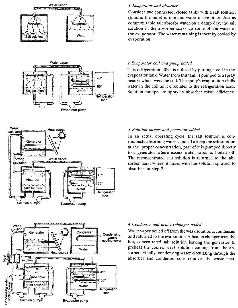
FIG. 2 The steps taken to build a single-effect absorption refrigeration
cycle. The refrigeration load from this cycle (step 4) is a building chilled
water supply system. The heat source for the generator can be indirect fired
(steam, hot water, waste heat, or solar energy) or direct fired (natural gas).
(Carrier Corporation.)
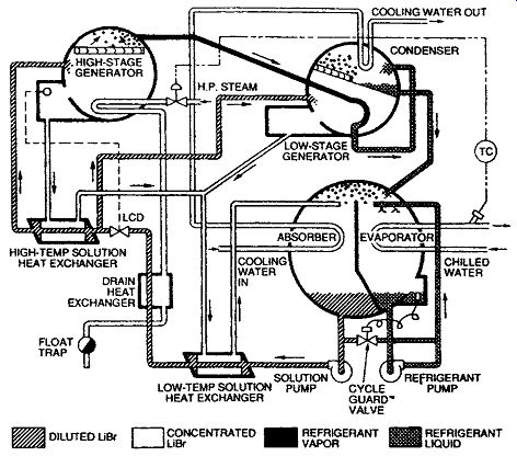
FIG. 3 Indirect-fired double-effect
absorption cycle. Lithium bromide and water are used in this cycle.
6. COOLING-ONLY SYSTEMS
(a) Fans
Before the advent of mechanical air conditioning, cooling was commonly achieved with simple air motion provided by fans. The summer comfort chart shown in Fig. 4.8 encourages increased air motion as a way to extend comfort into air temperatures in the mid-80s ºF. As a general rule, people will perceive a 1Fº decrease in air temperature for every 15 fpm increase in air speed past the body (about a 1Cº decrease for every 1 m/s increase). Ceiling fans are often installed and run at slow speed to de-stratify warm air at the ceiling in winter; they can be run at higher speed in summer to pro vide added comfort through increased air motion.
The air motion produced by ceiling fans will vary with the fan height above the floor, the number of fans in a space, and the fan's power, speed, and blade size. FIG. 4 shows expected air speeds with one 48-in. (1220-mm) ceiling fan in a typical residential living room.
In the hot summer climate of Davis, California, an experimental house (sponsored by Pacific Gas & Electric, designed by the Rocky Mountain Institute) has eliminated a conventional cooling sys tem through a series of alternative approaches.
Fans play a major role: in addition to ceiling fans, a whole-house fan removes the hottest air from the central hallway, exhausting to the ventilated attic.
More thermal mass (tile floors, double drywall), an attic radiant barrier, and low-e, gas-filled windows are also used.
(b) Unit Air Conditioners
The device shown in FIG. 5 is perhaps the most commonly seen piece of mechanical equipment in the United States. Perched in windows in full view of passersby, these window-box air conditioners noisily remind us that many of our buildings still are not centrally mechanically cooled. Mechanical cooling was considered a luxury until long after World War II.
Built-in, through-wall air conditioners offer a low-first-cost way to provide separate zones for individual apartments, motel rooms, and so on (see Section 9.8). In noisy cities, the drone of these units masks street noise for the interior, thus potentially helping to promote relaxation. Unfortunately, such scattered units rarely afford the chance to conserve energy through the exchange of waste heat or the higher efficiencies that can accompany larger equipment. However, if turned on only when cooling is needed (i.e., when people are present), they can provide substantial savings over the larger always-on systems.
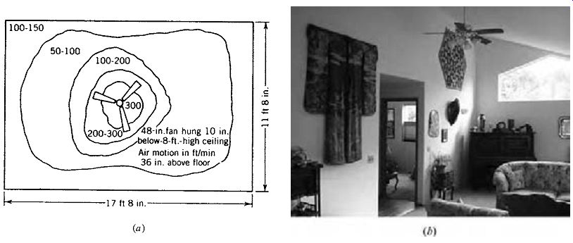
FIG. 4 Ceiling fans are
useful in heating and cooling. In winter, at slow speeds, they destratify warm
air at the ceiling. In summer (a) they extend the comfort zone by providing
increased air motion. Room size is typical of residential living rooms. (American
Society of Heating, Refrigerating and Air-Conditioning Engineers, Inc., from
1997 ASHRAE Handbook- Fundamentals.) (b) A ceiling fan is a visual feature
in this Oregon residence. (Nathan Majeski.)
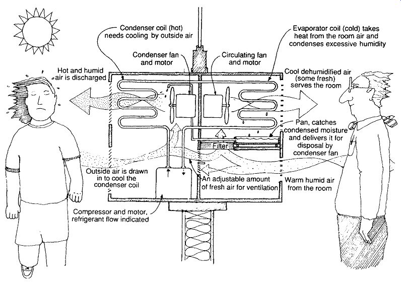
FIG. 5 Diagram of a typical through-the-wall air-conditioning (cooling)
unit. Direct heat exchange occurs between air and the process of evaporation
(on one side) and condensation (on the other) of the refrigerant. The unit
is self-contained, requiring access to outside air and electricity to power
the compressor and the two fans. Typical capacities are 1 to 2 tons (12,000
to 24,000 Btu/h [3.5 to 7 kW]).
(c) Evaporative Cooling: Misting
As explained in Section 8.12, the net effect of evaporative cooling is no total change in the heat content (enthalpy) of the treated air; its DB temperature is lowered, but there is an increase in RH. People feel cooler, although no change in total heat has occurred. One of the most direct approaches is a misting or fogging system whereby a fine spray of water droplets is blown into the air. A common application is for small outdoor areas-the team benches of football stadiums or refreshment pavilions. However, very large spaces in hot, dry climates can also benefit; FIG. 6 shows mist descending from a skylight diffuser in the Atocha railroad station in Madrid, Spain. A large space using fogging (in a Michigan conservatory) is shown later in Fig. 10.52.
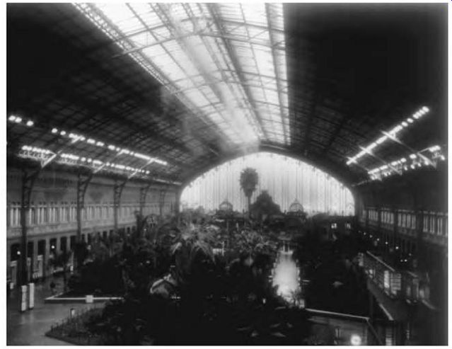
FIG. 6 Mist is sprayed from a diffusing system located high in the Atocha
railroad station in Madrid, Spain. It provides psychological reinforcement
of evaporative cooling in a hot, dry summer.
(d) Evaporative Cooling: Roof Spray
In the past, when roofs were poorly insulated, roof sprays were rather common ways to reduce heat gains. New variations promise new energy savings.
Roof color is the first consideration; white or near-white roofs are the first step toward energy savings through control of sol-air temperature.
However, emissivity is also involved; the higher the emissivity, the faster a roof surface reradiates its heat to the sky. TABLE 1 compares the solar absorptance, albedo (overall solar reflectance), and emittance of some common roofing materials. The combination of high albedo and high emittance resists solar heat gain most effectively. (It also promises to reduce the heat island effect in urban areas; see Section 3.) A solar reflectance index (SRI) was developed to allow quick comparisons between roofing products. The SRI scale ranges from 0 (approximately the combination of 5% albedo and 90% emittance; roughly equal to black asphalt shingles) to 100 at 80% albedo and 90% emittance (roughly equal to T-EPDM).
The night roof spray thermal storage system (NRSTS) cools water on a roof by night, using both night sky radiation and evaporation. The water is then stored for use the next day in building cooling.
The water can be stored either on the roof (below floating insulation, above a structural ceiling) or in a tank below the roof. When stored on the roof, it becomes a variant of the roof pond cooling system.
When stored in a tank, the water can be circulated through a cooling coil to pre-cool air before it enters the chiller-fed cooling coils. It is thus used to assist mechanical cooling. Three variations are shown in FIG. 7.
At a Nogales, Arizona, border patrol station, a 6500-ft 2 (604-m^2) flat white roof was retrofitted with an NRSTS, utilizing a 10,000-gal (37,850-L) above-ground tank. Over the summer of 1997, it averaged 250 Btu/ft^2 day of cooling. Water use at various sites has averaged 4 to 5 gal/h (15 to 19 L/h) per 1000 ft^2 (per 93 m^2) of roof area. Details are presented in Bourne and Hoeschele (1998).
(e) Evaporative Coolers
These are also affectionately termed swamp coolers and desert coolers and are familiar devices in hot, arid climates (FIG. 8). (They are used in other climates for special high-heat applications such as restaurant kitchens.) They require a small amount of electricity to run a fan and some water to increase the RH of the air they supply to the building. This process of cooling is explained in Section 8.14.
The typical evaporative cooler (shown in FIG. 8) needs full access to outdoor air and is thus often set on the roof; through-the-wall units are also available. Great quantities of dry, hot outdoor air are blown through pads kept moist by recirculated and makeup water. The "cooled" air is then delivered to the indoor space. The effect of the gently moving cool air is to cool the body and to produce further cooling by evaporation of body moisture.
Air introduced into the indoor space must then be exhausted for the system to operate properly. By selecting the room through which the air is exhausted, one can route cool air as desired in any chosen path from unit to relief opening.
The closer to the relief opening, the warmer the indoor air.
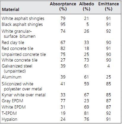
TABLE 1 Solar Performance of Roofing Materials
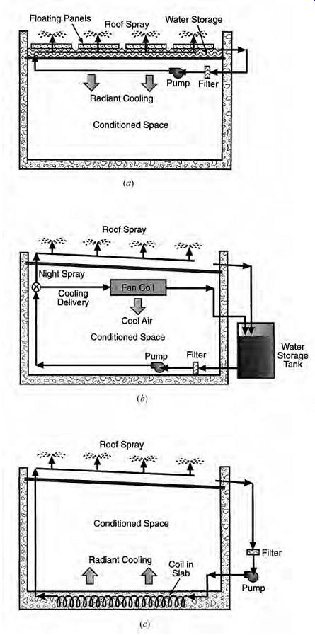
FIG. 7 Night roof spray thermal storage systems (NRSTS). (a) This version
approximates the performance of a roof pond.
(b) Remote water storage allows use of the cooled water at any time. (c) The floor slab is used as thermal storage in this version.
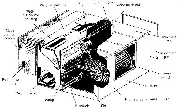
FIG. 8 The UltraCool evaporative cooler has a low profile and uses internal
components of plastic or stainless steel to reduce corrosion. Typical dimensions
for a 4000-cfm (1890-L/s) unit are 35 in. H × 42 in. W × 48 in. D (890 × 1070
× 1220 mm).
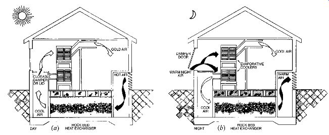
FIG. 9 Direct-indirect evaporative cooling utilizing a rock bed for storage
and heat exchange. (a) Day operation; (b) night operation. ( Environmental
Research Laboratory, University of Arizona.)
(f) Indirect Evaporative Cooling
The preceding discussion concerns the simplest application of evaporative cooling, known as the direct process (once-treated outdoor air directly introduced to the space). Unfortunately, some areas have such hot summer daytime conditions that these simple evaporative approaches cannot produce comfort indoors. Direct and indirect processes have been combined to achieve more "real" cooling and better indoor comfort conditions; a psychrometric process diagram is shown in Fig. 5.16.
One of several such approaches is shown in Figs. 9 and 10. Warm, rather dry night outside air is evaporatively cooled and fed into a rock bed. The air's temperature is low enough to cool the rock bed, and its RH is moderate. (At the same time, the house is directly evaporatively cooled by a second cooling unit.) FIG. 10 traces the process by day. Extremely hot, dry outdoor air (A) is drawn into the rock bed, where it is cooled by contact (D). It can then be passed through an evaporative cooler to achieve a better combination of RH and DB temperature (E). After picking up both sensible and latent heat, the air is exhausted (at approximately temperature F). Note that at condition F, it is still much cooler than outdoor air.
By comparison, simple direct evaporative cooling by day would have produced indoor sup ply air too hot and humid for comfort (B). Again, upon exhaust (C), it is still cooler than outdoor air.
Indirect evaporative cooling is combined with a direct refrigerant system in an innovative tent structure over a San Francisco department store (FIG. 11). Two layers of fiberglass, Teflon coated fabric, separated by an average of 12 in. (300 mm), are supported by a network of cables hung from eight masts. The tent roof covers about 70,000 ft^2 (6500 m^2) of sales floor; its 7% translucency to sunlight provides 450 to 550 footcandles of daylight. This greatly reduces the need for electric lighting, although some electric lamps, clipped onto exposed fire sprinkler pipes, are still used as accent lighting. About 3.5 W/ft^2 of solar gain, mostly in the form of this diffused daylight, penetrates the tent cover. When this solar gain is combined with heat gains from people and electric accent lights, a cooling load is always generated in San Francisco's mild climate, which rarely falls below 45ºF (7ºC). The roof's relatively high U-factor is thus advantageous in helping to lose heat. Because San Francisco overheats even more rarely, such low resistance to heat flow is not seriously disadvantageous in summer.
To remove this heat, four sets of direct refrigerant equipment are provided at the tent perimeter on grade. These feed into a perimeter plenum, from which the entire store is supplied with cooled air. The exhaust air is collected at the center and returned to help with the task of cooling. Indirect evaporative cooling (also called sensible evaporative refrigeration) units are used to cool air (see FIG. 11b). In this application, two units work in tandem. Air to be cooled (supply air) enters the heat exchanger of the first unit, which is cooled by evaporative cooling of outside air. During peak temperature periods, the supply air is only somewhat cooled by this process; sufficiently low temperatures for use on the interior are obtained by passing it through the second unit's heat exchanger. This second unit is cooled by evaporative cooling of the exhaust air from the store, which is cooler than outside air under summer conditions.
Thus, the exhaust air does some work beyond the direct cooling of the tent's interior. This two-stage, indirect evaporative cooling process allows the supply air to be cooled without the RH being raised, as would be the case if direct evaporative cooling were used.
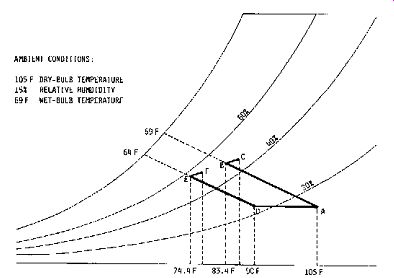
FIG. 10 Comparing direct (A to B to C) and indirect evaporative cooling
(A to D to E to F) on the psychrometric chart.
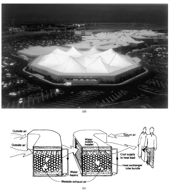
FIG. 11 Bullock's Department Store, San Mateo, California. (a) The eight-masted
white fabric roof, highly reflective to ward off solar heat, transmits about
7% of daylight to provide ample diffuse daylight for sales areas. (b) Cooling
is provided by a two stage, indirect evaporative cooling system, which uses
much less energy than does conventional compressive refrigeration.
7. HEATING-ONLY SYSTEMS
There are substantial areas of North America in which the summers are so mild, but winters so cold, that heating systems are installed but not cooling systems. This is most common for residences and small commercial buildings.
Where should heating devices be placed within a space? The relative comfort in heated rooms from entire ceilings or floors as a heat source is discussed in Section 4. Figure 4.10 shows dissatisfaction with increased air velocity (the warmer the air, the higher the velocity tolerated), Fig. 4.11 shows dissatisfaction with asymmetric radiation (warmer ceilings were less tolerated), and Fig. 4.12 shows dissatisfaction with vertical air temperature differences (cold floors were less tolerated). FIG. 12 shows why designers usually locate heat sources below windows, despite the fact that warmer temperatures just inside an exterior wall will drive more heat through the wall in cold weather (heat loss = U × A × ?t). As windows and walls become better insulated, their interior surface temperatures rise, and the need for heat at the edge grows less. Indeed, with superinsulated components, the need for space heat disappears because internal gains from the sun, lights, appliances, and occupants can heat the space.
FIG. 12 Locating a heat source near an interior wall (a) encourages a cold
draft along the floor in winter. Below a window (b) it evens the temperature
throughout the room but also causes more heat loss through the window.
(a) Wood Heating Devices
After the sun, the most ancient method of heating is the radiant effect of fire. With each step from campfire to fireplace to wood stove, more of the fuel's heat was captured for the room rather than wasted to the outdoors (FIG. 13). Although many people enjoy the sight, sound, and smell of the open fireplace, the tightly enclosed wood stove with a catalytic combustor is a substantially more efficient and less polluting approach to heating.
Indoor as well as outdoor air pollution is a serious issue with fireplaces and stoves. Combustion generates carbon monoxide, breathable particulates, and, at times, nitrogen dioxide. Wood smoke can cause nose and throat irritation; it can remain in the lungs, and it can trigger asthmatic attacks.
Keeping a clean chimney, burning small, hot fires rather than large, smoky ones, using seasoned wood, and ensuring adequate ventilation to the wood-burning device are strategies to minimize pollution and risk.
Open fireplaces may be lovely to look at, but the amount of air exhausted up the chimney can quickly cause more heat losses than heat gained from the fire. The colder the outside air, the greater the net heat loss. Masonry mass around fireplaces can store and release some heat; for energy conservation, the mass should be surrounded by the building rather than located on an exterior wall. ANSI/ASHRAE Standard 90.2 requires fireplaces to have a tight-fitting damper, firebox doors, and a source of outside combustion air within the firebox.
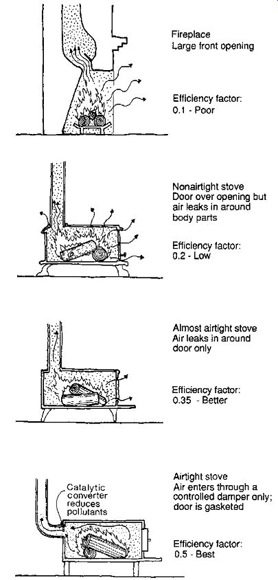
FIG. 13 Wood-burning devices have substantially increased in efficiency
since the time of the open fireplace.
Wood stoves are available in a wide variety of styles and are made of several materials. The heating capacities of such stoves are often difficult to determine. Manufacturers rarely specify the Btu/h output, which depends on the density, moisture content, and burn time of the wood fuel. Wood that has been split, loosely stacked, and covered from rain for at least 6 months should achieve a moisture content of about 20% by weight. The following sizing procedure assumes no more than this 20% moisture content. For more details, see Issue 35 of Alternative Sources of Energy Magazine (1978).
The formula for the hourly heat output to a room from a wood stove is
Btu/h =
( )( )( )(7000) VED T
where V = useful (loadable) volume of the stove (ft 3)
E = percent efficiency, expressed as a decimal (<1.0); see FIG. 13 D = density of the wood fuel (TABLE 2) T = burn time (hours) for a complete load of fire wood; usually assumed at an 8-hour minimum 7000 = Btu/lb of firewood, 20% moisture content "Bone-dry" wood can be assumed to have 8600 Btu/lb (20,000 kJ/kg). Note that a drop in burn time increases the heat output; it is evident that when the air supply is increased to the stove, the fire burns hotter, consuming the wood more quickly. To meet the design heat loss (worst condition) for a room, burn times of 8 to 10 hours should be assumed. Stoves rarely need relighting with a 10-hour burn time.
Pellet stoves were introduced in 1984 and have several desirable characteristics. The pellets are made from densified quality sawdust, a manufacturing by-product. The form and content of this fuel pro duce a highly efficient burn with less pollution emit ted. The fuel is cleaner and takes less storage space than cordwood; an electric auger automatically feeds fuel into the burn-place to maintain a fire.
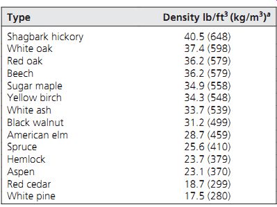
TABLE 2 Approximate Average Wood Density
From 10,000 to 50,000 Btu/h (2930 to 14,650 W) are produced, depending on the model and operating settings.
Wood stoves are frequently used as the sole mechanical heat source for an entire building, such as a residence or a small commercial building that is passively solar heated. Because radiant heat is the dominant form of heat output, the areas that "see" the stove get most of the benefit. How ever, circulating stoves convert a larger portion of their heat to convected heat, which produces a layer of hot air at ceiling level. By providing a path between rooms at the ceiling, this hot air will slowly spread throughout a building; it also easily finds its way upstairs, because warm air rises. The more thermally massive the ceiling construction, the longer it will store and reradiate the heat from this warm air mass.
The flue leading from a wood stove carries very hot gases that are a potential source of heat (and pollution). The flue can be exposed to a space, making its radiant heat available, or simple heat exchangers can be constructed (such as the pre heating of domestic hot water). More elaborate heat recovery devices-for boiler flue heat recovery-are discussed in Section 10.3.
Catalytic combustors, a recent development, reduce the air pollution from wood burning. These devices are honeycomb-shaped, chemically treated disks as much as 6 in. in diameter and 3 in. thick (150 mm in diameter, 75 mm thick). They are either inserted in the flue or built into the stove itself. When wood smoke passes through the combustor, it reacts with the chemical and ignites at a much lower temperature; this causes gases to burn that otherwise would have gone up the flue. The result is more heat produced, less creosote buildup in the flue, and fewer pollutants in the atmosphere.
Like the catalytic converters in autos, these devices impose limits on the fuel: plastic, colored newsprint, metallic substances, and sulfur are ruinous to combustors, which means that the stove must be used as a wood burner, not a trash incinerator.
Wood stoves have a larger impact on building design than do most other heating devices.
Either noncombustible materials must be placed below and around them or minimum clearance to ordinary combustible building materials must be provided. Furniture arrangements and circulation paths must be designed with the very hot stove surfaces in mind. Hot spots occur near the stove; cold spots occur whenever visual access to the stove is blocked. Thermally massive materials near the stove are advantageous in leveling the large temperature swings that can accompany the on-off cycle of the stove; this affinity for thermal mass has made the wood stove a popular choice for backup heat in passively solar-heated buildings. Finally, the amount of space required for wood storage should not be overlooked; recall the impact of the wood storage space on the house shown in Fig. 2.2. A covered, well-ventilated, easily accessible, and quite large space is optimum.
Masonry heaters overcome many of the metal wood stoves' disadvantages. Their footprint is rather small compared to their height; typically, they are used to heat the entire building (such as a residence). An inner vertical firebox supports a hot, clean burn, resulting in efficient combustion; combustion gases then flow downward in outer chambers, transferring heat to exterior masonry surfaces. In Finnish masonry heaters, this is termed contraflow (FIG. 14). Cool air at the floor of the room flows upward as it is heated by contact with this masonry; the temperature difference between masonry and air remains fairly constant, with the highest temperatures at the top. Heat is gentle and even; dangerously hot surfaces are avoided. Fires may be built at 6:00 P.M., and combustion is completed by a family's bedtime; the heat continues to radiate all night, but no fire is burning while people sleep. Research at Finland's Tampere University of Technology has resulted in optimum masonry heater designs, described in Barden and Hyytiainen (1993).
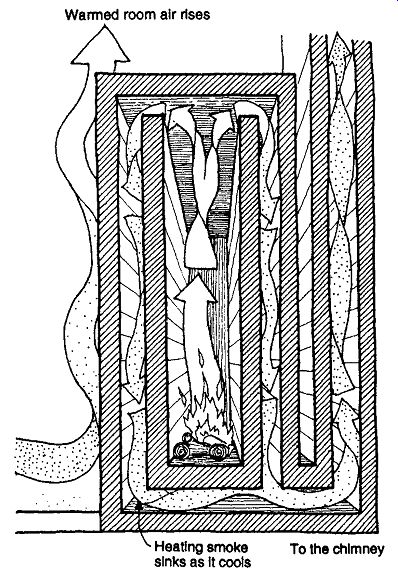
FIG. 14 The Finnish contraflow masonry heater.
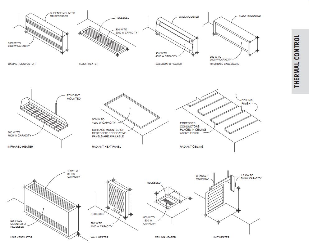
FIG. 15 Varieties of electric resistance heating units.
(b) Electric Resistance Heaters
These common devices carry the disadvantage of using high-grade energy to do a low-grade task, as shown in Fig. 2.6. Their advantages, however, are impressive: low first cost and individual thermostatic control that can easily be used to make each room a separate heating zone. Thus, the energy wasted at the electricity-generating plant (usually 60% to 70%) can be partially "recovered" at the building, where unused rooms can remain unheated. A few of the many types of electric resistance heaters are shown in FIG. 15. As in the case of metal wood stoves, surfaces can sometimes reach high temperatures, requiring care in the location of heaters relative to furniture placement, draperies, and traffic flow. Electric heaters are sized by their capacity in kilowatts (1 kW = 3413 Btu/h). The maximum watt density allowed is 250 W per linear foot of heater (820 W per linear meter).
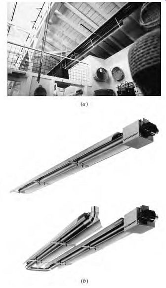
FIG. 16 A high-intensity infrared heater adds to the historic atmosphere
of this retail store in an old warehouse (a). Exposed mechanical equipment
includes the chains that operate the clerestory windows. The vented gas heater
has an adjustable reflector that enables its radiant heat to be directed. (Clark-Ditton
Architects, Eugene, OR.) (b) Vented gas high-intensity infrared heaters are
available in both straight-line and U-shaped units. (c) Gas-Fired Heaters
Radiant heaters fired with either natural gas or pro pane are often found in semi-outdoor locations such as loading docks and repair shops. When vented, they can be used in more traditional environments such as the retail store in a remodeled warehouse shown in FIG. 16. Their advantage is that they heat surfaces first rather than air, so that comfort is obtained without the need for high air temperatures. When high rates of air exchange are expected, high-intensity radiant heaters are often used.
Radiant heaters should be sized by the surface temperature change they produce. Many manufacturers specify this surface delta_t for specified mounting heights and angles relative to the surface to be heated.
Gas-fired baseboard heaters are also available, using either natural gas or propane. They heat by both convection and radiation, as do their electric counterparts. At a steady-state efficiency of 80%, they use a lower-grade resource (than electricity) to do this lower-grade task. They are direct vented (using a built-in fan) to the outside, and therefore must be installed on or near an exterior wall; vents are 1½ in. in diameter, with a maximum length of 19 in. (38 mm in diameter, 483 mm in length). With a cross section of 9 in. high by 5 in. deep (230 mm × 130 mm), a 48-in. (1220-mm) length will deliver 5800 Btu/h (1700 W); a 72-in. (1830-mm) length will deliver 9400 Btu/h (2755 W).
(d) Ceiling Electric Resistance Heat
Ceilings can be constructed to include wiring for electric resistance heating (FIG. 17). Because the ceiling is not touched by occupants, it can be safely heated to a rather high temperature. The primary disadvantage of ceiling heat is that hot air stratifies just below the ceiling, so that air motion is discouraged; remember also that Figs. 4.11 and 4.12 predict more discomfort with a warmer ceiling. Finally, the wires are hidden within the ceiling surface, and unwary occupants can puncture wires while installing hooks or additional light fixtures.
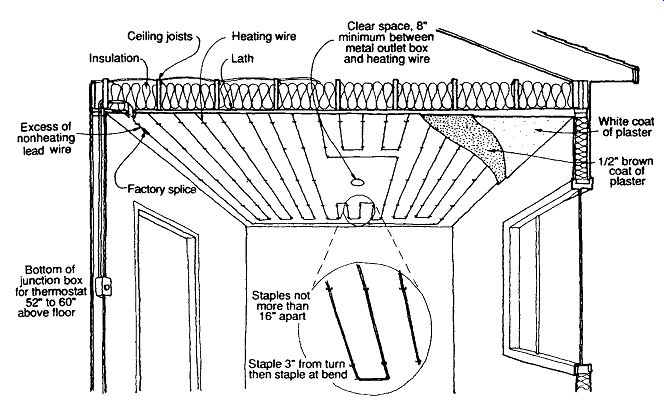
FIG. 17 Radiant heating electrical cable is installed prior to completion
of a plaster ceiling.
(e) Hot Water Boilers
The remaining choices for whole-building heating systems are discussed in the following order: (1) hot water and (2) forced air. Such systems include a fuel, a heat source, a "mover" (such as a pump or fan), a distribution system, a heat exchanger or terminal within the space, and a control system.
Hot water boilers are rated according to heating capacity by several different categories. Heating capacity is the rate of useful heat output with the boiler operating under steady-state conditions, often expressed in MBh (1000 Btu/h). This "useful heat" assumes that the boiler is within the heated envelope of the building; thus, the heat that escapes from the boiler walls is avail able to help heat the building. AFUE, the annual fuel utilization efficiency, is defined as 100% minus the losses up the stack during both the on and off cycles, and the losses due to infiltration of outdoor air to replace the air used for combustion and for draft control. Finally, the net I = B = R rating (a designation of the Institute of Boiler and Radiator Manufacturers) is published by the Hydronics Institute Division of the Gas Appliance Manufacturers Association (GAMA). The net I = B = R rating load is lower than the heating capacity rating, because it consists only of the heating to be delivered to the spaces and excludes the heat loss of the boiler itself.
Select a boiler whose rating matches the calculated critical heat loss of the house or building; too small a boiler results in lower indoor temperatures at design conditions; too large a boiler costs more and is a waste of space. When using AFUE to select an efficient boiler, take care to see that the assumptions about "inches of water draft" and percentage CO2 are similar for the boilers being compared. Minimum AFUEs are specified both in ANSI/ASHRAE Standard 90.2, Energy-Efficient Design of Low-Rise Residential Buildings, and in ANSI/ASHRAE/IESNA 90.1, Energy Standard for Buildings Except Low-Rise Residential Buildings.
Boilers and their accessories comprise a wide inventory. A few selected types are discussed:
1. Oil-fired steel boiler. A refractory chamber receives the hot flame of the oil fire. Combustion continues within the chamber and the fire tubes.
Smoke leaves through the breeching at the rear. Water, outside the chamber, receives the heat generated in the combustion chamber. If a domestic hot water coil is connected for use, a larger-capacity boiler is selected. An aqua stat (water thermostat) turns on the burner whenever the boiler water cools off, thereby maintaining a reservoir of hot water ready for heating the building.
2. Gas-fired cast-iron hot water boiler (FIG. 18). Cast-iron sections contain water that is heated by hot gases rising through these sections.
Output is related to the number of sections.
Additional heat is gained from a heat extractor in the flue. With induced draft combustion, condensing unit in the flue, and intermittent electronic ignition instead of a pilot light, up to 90% AFUE is attainable. The American Gas Association (AGA) sets standards for gas-fired equipment.
3. Oil-fired, cast-iron hot water boiler. Primary and secondary air for combustion may be regulated at the burner unit. Flame enters the refractory chamber and continues around the outside of the water-filled cast-iron sections.
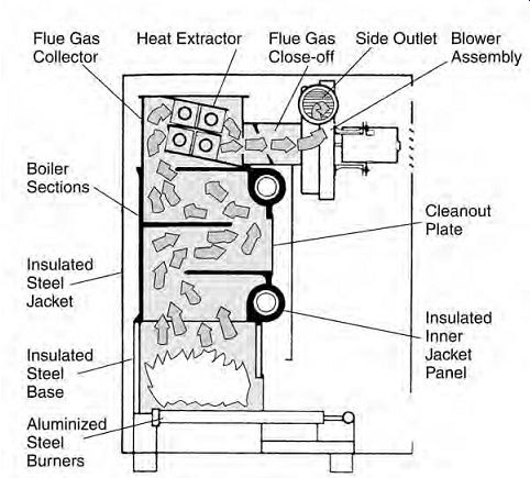
FIG. 18 Gas-fired cast-iron sectional boiler for hot water heating. Very
high operating efficiency is possible; no chimney is required, as lower-temperature
exhaust gases can be vented through the wall to the exterior.
(f) Hot Water Baseboard and Radiator Systems
Hot water heating circuits that serve baseboards or radiators come in four principal arrangements.
Fig. 19a shows the series loop system, usually run at the building's perimeter. The water flows to and through each baseboard or fintube in turn.
Obviously, the water at the end of the circuit is a little cooler, but because in all hot water systems the water temperature drop seldom exceeds 20Fº (11Cº) in residences, the average temperature can usually be used to select the baseboard or other elements. Valves at each heating element are not possible, because any valve would shut off the entire loop. Adjustment is by a damper at each baseboard, which reduces the natural convection of air over the fins. This is a one-zone system-all elements on, or off, together. There is no general rule about the maximum allowable length of a water circuit, but for long runs, the pipe size can be increased or several loops used in parallel to create more than one thermal zone.
The one-pipe system shown in Figs. 19b and 20 is a very popular choice. Special fit tings act to divert part of the flow into each base board. A valve may be used at each one to allow for reduced heat or for a complete shutoff to con serve energy-an advantage that the loop sys tem does not provide. The one-pipe system uses a little more piping and thus is not as economical to install as the loop system, in which piping is minimal. Again, the supply water temperature will be lower at the end of the run than at the beginning.
The two-pipe reverse-return shown in FIG. 19c provides the same supply water tempera ture to each baseboard or radiator, because it is not cooled either by passing through a previous baseboard or accepting the cooler return water.
Equal friction, resulting in equal flow, is achieved through all baseboards (numbers 1 to 5) by reversing the return instead of running it directly back to the boiler. This equality is effected by equal lengths of water flow through any baseboard together with its lengths of supply-and-return main. More pipe is required for this system than for the systems shown in FIG. 19a or 9.19b.
FIG. 19d shows an arrangement that is not usually favored because the path of water through baseboard number 1 is much shorter than that through the others, especially number 5. Baseboard number 5 could easily be undesirably cool, because it is short-circuited by the others.
Pipe expansion requires expansion joints in long runs of pipe and clearance around all pipes passing through walls and floors. Each time a hydronic system changes from room temperature to a heated condition, the piping will undergo the following expansion, assuming a 70ºF (21ºC) initial temperature:
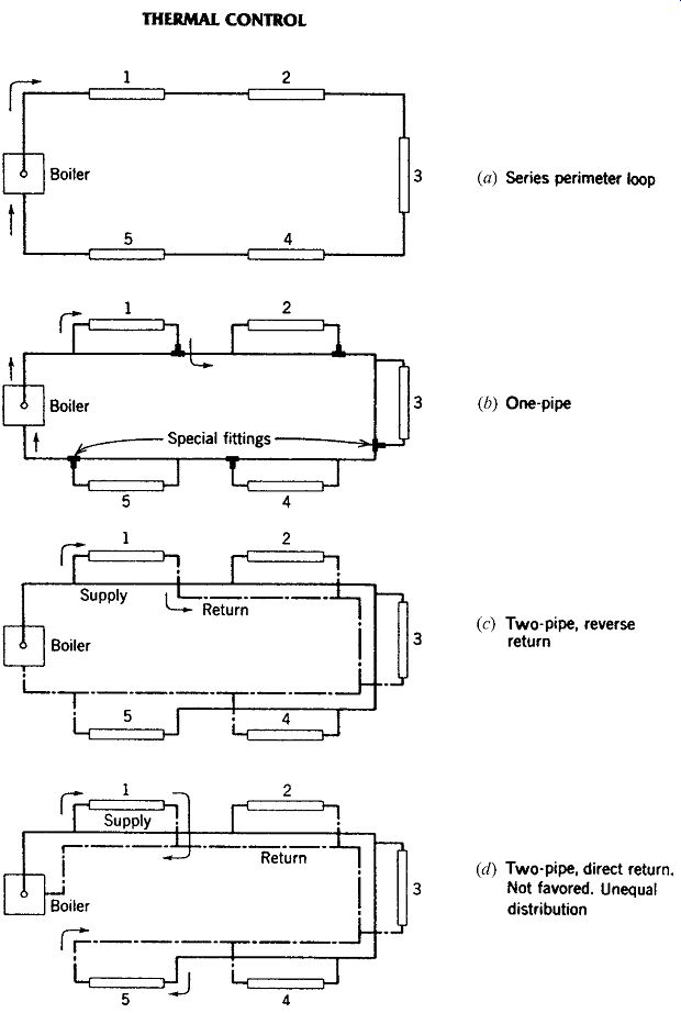
FIG. 19 Diagrams of hydronic distribution options (a, b, c, d), shown in
plan view. Baseboard convectors are shown here. Controls are not shown.
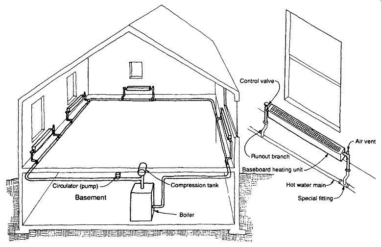
FIG. 20 One-pipe hydronic system.
An air cushion tank, compression tank, or expansion tank is a closed tank containing air, usually located above the boiler. When the water in the system is heated, it expands, compressing the air trapped in the tank. This tank allows for the usual range of temperatures within the system, including temperatures above the usual boiling point of water, without the frequent opening of the pressure relief valve. One type of air cushion tank, called a diaphragm tank, separates the air and water with an inert, flexible material; this prevents re-absorption of the air by the water.
For a conventional (unpressurized) air cushion tank, allow 1 gallon of tank capacity for every 5000 Btu/h (1 L for every 385 W) of total system heat loss. For a pressurized tank of at least 8 lb/in^2 (55 kPa), allow 1 gallon of tank capacity for each 7000 Btu/h (1 L for each 540 W), or see the manufacturer's recommendations.
Air vents and water drains are part of the distribution system. Except for the necessary air cushion in the upper part of the compression tank above the boiler, air must not be allowed to accumulate at high points in the piping or at the convector branches. Air vents at all high points relieve these possible air pockets that would otherwise make the system air-bound and inoperative.
If a system is drained and left idle in a cold house, water trapped in low points can freeze and burst the tubing or fittings. Operable drain valves must be provided at such locations and, of course, at the bottom of the boiler, as shown in FIG. 21.
Hydronic and electrical controls allow automatic operation, described in FIG. 21. There are two options for system control:
1. As in FIG. 21, the thermostat controls the circulating pump and the boiler. In colder weather, the system operates almost continuously, and the average temperature in the system gradually rises.
2. The thermostat controls only the boiler, and the circulating pump operates continuously.
This uses more energy for the pump but minimizes system temperature variation and thus the possibility of expansion noises.
Makeup water is added as required, the air level in the tank is regulated by the air control fittings, and the circulator and burner operate as controlled by the aquastat and thermo stat. If air vents in the piping are not automatic, they will require periodic manual "bleeding" of unwanted air.
Circulating pumps are used to overcome the friction of flow in the piping and fittings and to deliver water at a rate sufficient to offset the hourly heat loss of the house or building.
Pipe insulation is required whenever the pipes are outside the heated envelope of the building; ANSI/ASHRAE Standard 90.2 specifies insulation appropriate to the temperature of the heated water.
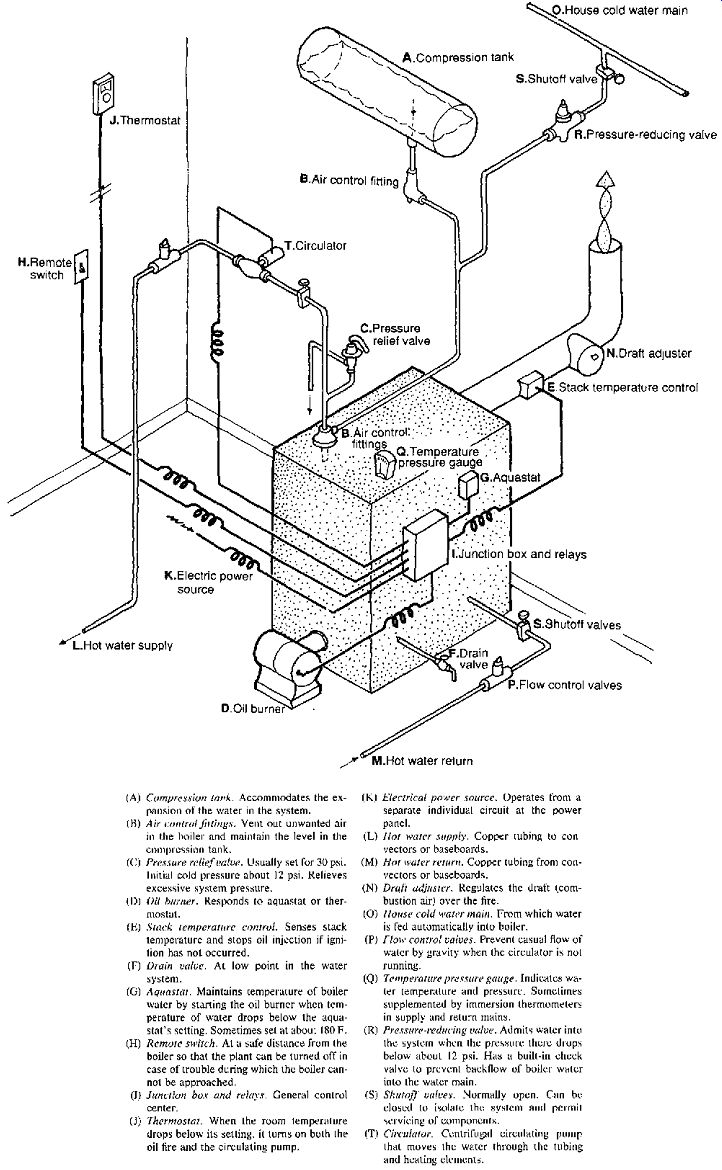
FIG. 21 An oil-fired boiler and its hydronic and electrical controls.
(g) Radiant Panels
Radiant floors have several comfort advantages over radiant ceilings. The components are largely the same as in the baseboard/radiator systems, except that now whole coils of pipes replace the individual radiators and baseboards. A balancing valve should be installed on each coil. Where uninsulated spaces underlie floors (or are above ceilings), special attention should be paid to adequate insulation, because the radiant panel will generate especially high temperatures, and thus a very high delta_t through the floor (or ceiling).
Thanks to better insulation, today's buildings often require panels smaller in area than the floor (or ceiling) area available. In a conventional radiant panel system, the panel is placed nearest the exterior walls, where the heat loss is greatest. In a solar heated building, this is not so clear. If the panel heats the floor surface just inside south-facing glass, how much warming will be left to the sun? A preheated slab will absorb much less solar radiation. However, in cloudy cold weather, the area closest to the south glass could become uncomfortably cool.
In the past, copper tubing was widely used for the heating coils. This typically involved a number of connections within a coil; each represented a potential point of failure over the life of the panel.
Today, coils are typically one-piece and are made of synthetic materials such as cross-linked polyethylene tubing. When the floor is concrete or other cast-in-place material, the coil is either directly embedded in the slab (tied down to resist floating during the pour) or stapled to an underfloor, over which the slab is poured. Radiant floors with coils underneath wood floors are increasingly popular.
Rugs or carpets over radiant floors are a mixed blessing; they are soft on the feet but interfere with the exchange of heat. Special under-carpet pads can facilitate heat transfer; higher water temperatures can be used in the coils, because skin contact with the floor is prevented by the carpet.
(h) Hydronic Heating Sizing
The calculations for the sizing of a water distribution system are based upon the required flow and the friction in the piping. (For a domestic water sup ply, another factor is the vertical distance the water must be raised. In closed loop space heating systems, however, the weight of the cooler water falling back to the boiler essentially counterbalances the weight of the hot water being raised. Furthermore, gravity helps the hot-lighter-water rise and the cooler water fall.)
The key to pipe sizing is the overall required flow rate. Ordinarily, the temperature drop that occurs as the hot supply water gives up heat to the space (through the convector) is about 20Fº [11Cº] in residences; in commercial applications, 30, 40, or 50Fº (17, 22, or 28Cº) temperature drops are also common, as recommended by the manufacturers of unit heaters and convectors. Because the entire building's design heat loss is overcome by this system, in I-P units, total flow rate, gpm
= design heat loss, Btu/h 20Fº 60min/h × × ×× 8 lb/gal 1Btu/ lb Fº
= design heat loss 9600 In SI units, total flow rate, L/s
= design heat loss, W Cº 1kg / L Wsec 11 4180 ×× / /kgCº
= design heat loss 45 980 ,
Then, using Section 21.11, we can account for friction through piping and fittings and can size the main supply and return pipes. The same procedure can be applied to branches, proportioned to the heat they must deliver. The total friction to be overcome in the most distant run is then converted from total psi to feet of head, with each foot of head = 0.433 psi (the pressure exerted by a foot-high column of water). In SI, 1 ft of water = 2.99 kPa.
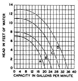
FIG. 22 Typical pump capacity (or performance) curves for four pumps used
in hydronic heating systems. One foot of water = 2.99 kPa; 1 gpm = 0.0631 L/s.
With both the friction of the system expressed in feet of water, or head, and the flow rate established, a pump can be selected. FIG. 22 shows typical performance curves for four pumps. The designer enters the curve with a desired flow rate, then selects the pump with a head capacity greater than or equal to the head required. Pump performance curves are provided by the manufacturer.
The critical choice, however, is not pipe size. It is relatively easy to distribute such small-diameter pipes within wall and floor/ceiling construction. Rather, the critical choice is the hot-water supply temperature: the higher this temperature, the smaller the convector units that discharge the heat to each space. However, higher temperatures endanger occupants, who may suffer skin burns if they touch exposed parts of the convectors or the distribution tree. Higher temperatures also can lead to steam within the boiler/distribution tree, although the system is under pressure and therefore the boiling point is greater than 212ºF (100ºC). These systems are not designed to accommodate steam, and serious injury can sometimes result. A safer choice of average water distribution temperature is 180ºF, even though this temperature results in larger con vectors. A slightly lower annual average energy consumption should accompany the lower distribution temperature.
TABLE 3 Hydronic Baseboard Convectors
Baseboard convector selection is then made from the manufacturer's data tables, such as the one shown in TABLE 3. The two common baseboard types are RC, usually cast iron with a water-backed front surface and an extended rear heating surface, and finned tube, a metal tube with an extended surface in the form of fins, usually placed behind a metal enclosure.
FIG. 23 Three-zone, multicircuit, one-pipe system. (a) Each convector has
connections to the one pipe. (b) Boiler, piping, and water controls suitable
for this three-zone, one-pipe system. Each one-pipe circuit should be provided
with two flow-control valves and a circulator (also called a booster or pump)
on the supply (or return) pipe. (ITT Bell and Gossett.)
(i) Hydronic Zoning
FIG. 23 shows that zoning is relatively easy to accomplish with hydronic systems. The installation shown in the figure is made up of three separately heated areas-the first, second, and third floors. Each can be heated to different temperatures as called for by thermostats in each separate apartment. For example, if only the thermostat serving the second floor (zone B) calls for heat, it turns on pump B. Flow-control valves B open, admitting hot water from the boiler header to main B. Flow-control valves A and C remain closed, preventing flow in mains A and C. Any or all of the zones may operate at one time. The boiler keeps a supply of hot water continually ready to supply any zone on demand. This is achieved by an aquastat immersed in the boiler water. When the boiler water drops below the prescribed temperature, it turns on the firing device, such as an oil burner or a gas burner, which brings the water up to the temperature setpoint. If an over head main supplies downfeed, as in the first floor of this installation, special downfeed supply and return fittings are necessary. For the second- and third-floor zones, one special return tee is sufficient. If the designer also elects to use a special upfeed supply tee of the venturi type, higher out puts of the convectors will result.
Two of the more famous residences in the Mid west utilize hydronic systems. Frank Lloyd Wright's Robie House (Chicago) has wall radiators integrated below the north windows in the living room.
Underfloor radiators with grilles in the floor were provided for below the full-height south windows but were apparently never installed. The boiler sits in a basement room. Mies van der Rohe's Farns worth House ( Fox River, Illinois) preserves its four walls of ceiling-to-floor glass by concealing radiant heating pipes in the floor slab. The boiler sits within the central utility "closet." Today's radiators are designed to reflect the sleek and simple lines of contemporary architecture. The radiator is getting new exposure with some colorful and pleasing products (FIG. 24). The Mayer Art Center at Phillips Exeter Academy in New Hampshire (FIG. 25) features new exposed radiators in some older buildings. These radiators are based on simple components (typically, 2¾ in. [70 mm] wide) that can be combined in many heights and widths, inviting the designer to feature them rather than to hide them in metal cabinets.
FIG. 24 Hot water radiators are available in bright colors and are based
on simple components.
FIG. 25 Hot water radiators fit below a window (a) at the Mayer Art Center,
Phillips Exeter Academy, Exeter, New Hampshire. Amsler Hagenah MacLean, Architects.
(Alex Beatty.) (b) Radiator formed by flat tubes.
(j) Heating Equipment Efficiency, Combustion, and Fuel Storage
As fuels burn to produce heat, they require oxygen to support the combustion. Because oxygen constitutes only about one-fifth of the volume of air, reasonably large rates of airflow are required. The air should be drawn in from outdoors at a position close to the fuel burner or (preferably) led to this location by a duct. ANSI/ASHRAE Standard 90.2 calls for 0.5 cfm/1000 Btu/h (1 L/s per 1242 W). This supply duct should be arranged to remain open at all times. Although permitted by Standard 90.2, this combustion air should not be drawn from the general building space. It is a waste of energy, and contemporary "tight" construction inhibits such airflow. A dangerous condition is created whenever flue stack flow is restricted.
High-efficiency boilers and furnaces manage to remove so much heat from the exhaust gases that smaller flues at much lower temperatures result.
These relatively small pipes can be vented through a wall to the exterior. Eliminating a chimney has lessened the impact on the building design of such boilers and furnaces.
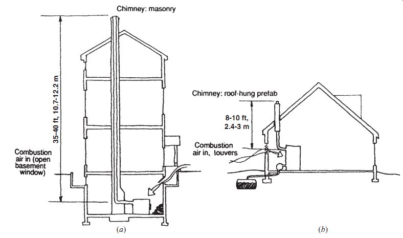
FIG. 26 The need for 40-ft (12-m) chimneys (a) has been eliminated by controlled
draft in burners (b) and by the use of high efficiency heating equipment
that can be directly vented to the exterior. Note the buried fuel oil tank,
a potential environmental threat.
For older or less-efficient fuel-burning equipment, it is important that when chimneys carry high-temperature flue gases, they be safely isolated from combustible construction to prevent the possibility of fire. The size of the flue will depend upon the boiler or furnace selected. Flue height (FIG. 26a) had traditionally been 35 to 40 ft (11 to 12 m). The function of providing a draft, for which chimney height was an important consideration, is now provided by fans. For example, oil is injected under pressure, accompanied by air, and forced in by a fan. Often a draft adjuster in the breeching (smoke pipe) that carries the flue gases to the chimney is arranged to open slightly to reduce the normal stack draft. If increased draft is ever required, an induced draft fan that puts suction on the flue side of the fire is usually chosen instead of greater stack height.
Draft hoods above gas burners prevent downdraft from blowing out the flames.
Prefabricated chimneys (FIG. 26b) are replacing with increasing frequency the bulkier and heavier field-built masonry. They offer a number of advantages and can be easily supported on a nor mal structure.
The storage space to be allowed for fuel oil depends on the proximity of the supplier and the space available at the building. For oil, when more than 275 gal (1040 L) was stored, it was common practice to use an outside tank buried in the ground.
This practice eventually led to leaking tanks and contaminated soil and groundwater. Thus, several factors converged to discourage the use of oil: a cleaner and more efficient alternative (natural gas), few basements in new construction where oil tanks might be stored, and unsightly outdoor above ground oil tanks.
Both ANSI/ASHRAE Standard 90.2 and ANSI/ASHRAE/IESNA 90.1 specify minimum efficiency ratings for heating and cooling equipment.
Depending upon the size and the type, one of these terms will apply:
Annual fuel utilization efficiency (AFUE) is the ratio of annual fuel output energy to annual input energy, which includes any non-season pilot input loss.
Coefficient of performance (COP) is defined slightly differently, depending upon the task. For cooling, it is the ratio of the rate of heat removal to the rate of energy input in consistent units, for a complete cooling system (or factory-assembled equipment), as tested under a nationally recognized standard or designated operating conditions. For heating (heat pump), it is the ratio of the rate of heat delivered to the rate of energy input in consistent units, for a complete heat pump system as tested under designated operating conditions. Supple mental heat is not included in this definition.
Energy efficiency ratio (EER) is the ratio of net equipment cooling capacity in Btu/h to the total rate of electric input in watts under designated operating conditions. (When consistent units are used, this ratio is the same as COP.) Integrated part load value (IPLV) is a single-number figure of merit based on part-load EER or COP expressing part-load efficiency for air conditioning and heat pump equipment on the basis of weighted operation at various load capacities for the equipment.
Seasonal energy efficiency ratio (SEER) is the total cooling output of an air conditioner during its normal annual usage period for cooling, in Btu/h, divided by the total electric energy input during the same period, in watt-hours.
(k) Warm Air Heating Systems
These systems began to supersede the open fire place in about 1900. Originally, an iron furnace that stood in the middle of the basement was hand-fired by coal. Surrounding it was a sheet metal enclosure. An opening in its side near the bottom admitted cool combustion air that gravitated to the basement. A short duct from the top of the enclosure delivered the warm air by gravity to a large grille in the middle of the floor of the parlor.
Other rooms, including those in upper stories, shared a little of this warmth when doors were left open.
Very gradual changes had culminated by the middle of the twentieth century in systems essentially like the ones described in FIG. 27. The improvements included:
Automatic firing of oil or gas Operational and safety controls Ducted air to and from each room
Blowers to replace gravity Filters Adjustable registers
By the 1960s, the basement was beginning to disappear as sub-slab perimeter systems became popular for basementless houses (FIG. 28). The heat source was located centrally and fully within the insulated volume of the house; heat escaping from the unit itself merely helped heat the building.
In general, air was delivered from below, upward across windows, to be taken back at a central high return grille.
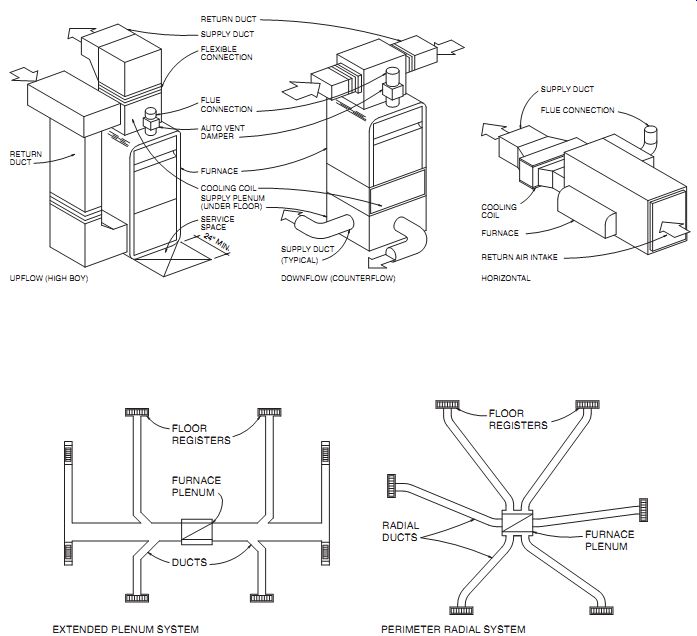
FIG. 27 Typical furnace types and duct distribution arrangements.
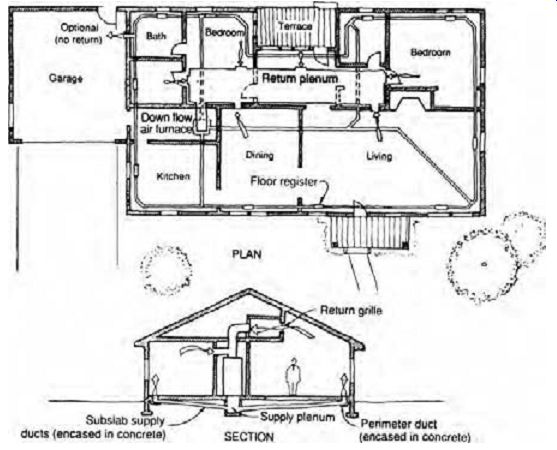
FIG. 28 Forced-warm-air, perimeter loop system, adaptable for a cooling
coil at the furnace. No returns are taken from the kitchen, baths, or garage.
When electricity was used instead of oil and gas for space heating, provisions for combustion, chimneys, and fuel storage were unnecessary.
Horizontal electric furnaces began to appear in shallow attics or above furred ceilings. Air was delivered down from ceilings across windows and taken back through door grilles and open plenum space. Electric resistance furnaces use more electricity than heat pumps to do the same heating task , so heat pumps have largely supplanted such furnaces.
As energy-saving design gained strength, insulated windows and well-insulated roofs, walls, and floors lessened the need for space heating. From a central furnace or heat pump, short ducts could deliver warm air to the inner side of each room, because warming at the insulated windows was less essential. Air returned to the unit through open grilles in doors and at the furnace or heat pump enclosure.
Comfort is one of warm air heating's advantages. The motion of air in the space helps to ensure uniform conditions and reasonably equal temperatures in all parts of a building. The building can quickly be warmed with a forced-air system. It is possible to clean both the recirculated air and the outdoor air by means of filters and other special air-cleaning equipment. Air may be circulated in non-heating seasons. Fresh air may be introduced to reduce odors and to make up the air exhausted by fans in kitchens, laundries, and bathrooms. Central cooling can be incorporated or introduced if ducts are designed originally to do so; cooling often calls for greater rates of air circulation. Humidification can be achieved by a humidifier in the air stream, and if cooling is included in the design, dehumidification can be accomplished in summer. For both heating and cooling, a common arrangement is to place the supply registers in the floor, below areas of glass. This is important for winter operation. With adequate attention to supply register placement, return grilles can be located so as to minimize return air ductwork. High return grilles pick up the warmer air for reheating at the equipment. In many systems, air circulates at all times and is warmed or cooled as required.
Planning for warm air systems begins with the attempt to locate the furnace reasonably close to the center of the building. After the system is designed, a furnace must be selected. It should be capable of burning fuel at a rate suitable to make up the building's hourly heat loss. The rate of air delivery depends on the air temperature rise that is planned. Finally, the motor and blower must be powerful enough to overcome the friction of air against metal in both the supply and return duct systems, as well as the friction of air flowing through the furnace, filters, registers, and grilles (see later FIG. 31). Minor adjustments can be made at the furnace to adapt to the demands of the system and the building.
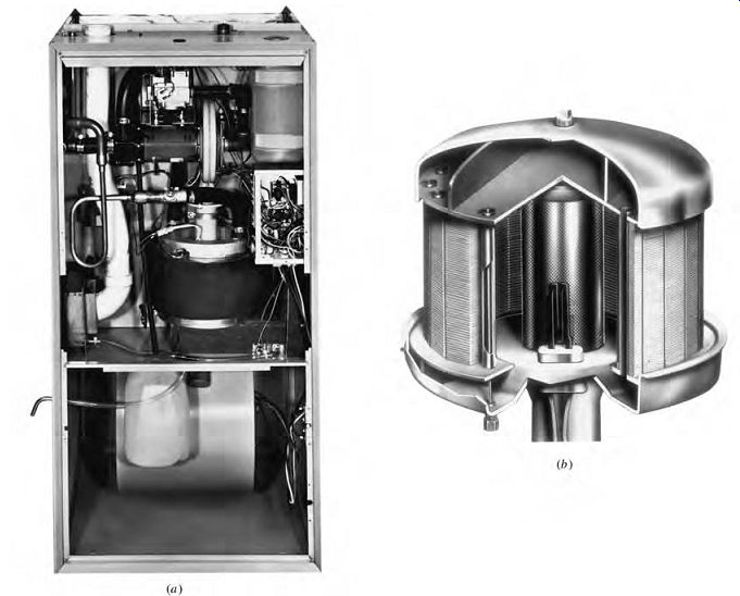
FIG. 29 Furnaces with
greatly increased operating efficiencies are now available. (a) An Amana gas
furnace. (b) The small, high efficiency heat exchanger utilized by this furnace,
which recovers heat from exhaust gases. (Amana Refrigeration, Inc.)
Some of the system components are discussed in the material that follows.
Furnaces have become much more efficient in recent years, thanks to forced-draft chimneys and heat exchangers, as shown in FIG. 29. Seasonal efficiencies of up to 95% are possible, in contrast to about 62% for older furnaces. The AFUE ratings for furnaces are based on an isolated combustion system that requires that all combustion and dilution air be drawn from outside.
FIG. 30 shows the relationship between a furnace, the duct distribution tree, and some elements of the spaces they serve.
Ducts are constructed of sheet metal or glass fiber and are either round or rectangular. Ductwork will conduct noise unless these suggestions are followed:
Do not place the blower too close to a return grille.
Select quiet motors and cushioned mountings.
Do not permit connection or contact of conduits or water piping with the blower housing.
Use a flexible connection between furnace bonnet and ductwork.
Ducts also can be lined with sound-absorbing material to further discourage noise transfer, but beware of materials that encourage mold and mildew growth.
Duct sizes may be selected on the basis of permissible air velocity in the duct (TABLE 4). (See Section 10.4 for more detailed duct-sizing procedures.)
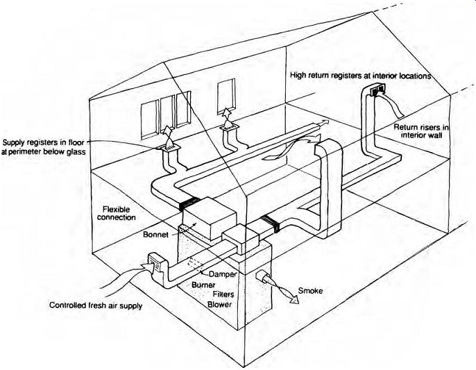
FIG. 30 Conventional warm-air furnace and ducts. Low supply registers under
windows and high return grilles at interior walls help ensure distribution
within the spaces.
FIG. 31 illustrates a device that simplifies duct sizing. At a glance,
it shows many duct cross-sectional configurations that will satisfy the combined
requirements of friction, airflow, and air velocity.

TABLE 4 Air Velocities for Ducts and Supply/Return Openings
FIG. 31 The Ductulator is a duct-sizing device available from the Trane
Company. The designer selects any two factors (e.g., friction and airflow volume),
and the device yields all the other factors (e.g., air velocity, diameter of
the round duct required, or combinations of rectangular-duct cross sections
required).
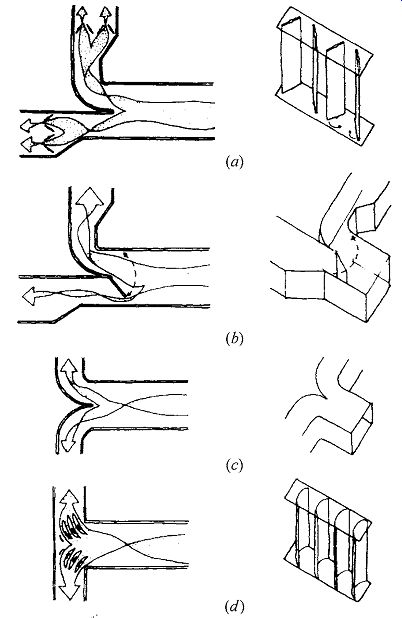
FIG. 32 Air controls in ducts. (a) Air adjustment by opposed blade dampers.
(b) Air adjustment by a splitter damper. (c) Conventional turns in ducts. (d)
Right-angle turns with turning vanes-a more compact method.
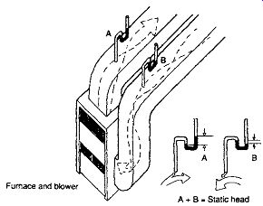
FIG. 33 The static head is the pressure, measured in inches of water (or
pascals), available to overcome friction in the entire system.
Dampers are necessary to balance the sys tem and adjust it to the desires of the occupants (FIG. 32). Splitter dampers are used where branch ducts leave the larger trunk ducts. The flow of each riser can be controlled by an adjust able damper in the basement at the foot of the riser. Labels should indicate the rooms served.
Some codes require dampers of fire-resistant material actuated by fusible links to prevent the possible spread of fire through a duct system (see Fig. 24.6). FIG. 32d shows how turning vanes can be used to assist airflow at sharp turns in duct work. Such assistance reduces friction within the ductwork, thus reducing the total static head (FIG. 33) against which the supply fan must work.
Supply registers should be equipped with dampers, and their vanes should be arranged to disperse the air and to reduce its velocity as soon as possible after it enters the room. This is commonly done by providing vanes that divert the air, half to the right and half to the left. When a supply register is in the corner of a room, it is best if the vanes deflect all the air away from the corner. Return grilles are of the slotted type in walls and of the grid type in floors. All registers and grills should be made tight at the duct connection. See Tables 9.4 and 9.5 for selection of registers based on output and recommended face velocity.
Controls: The burner is started and stopped by a thermostat, which is usually placed in or near the living room at a thermally stable location that is protected from cold drafts, direct sunlight, and the warming effects of nearby warm air registers.
A cut-in temperature of between 80º and 95ºF (27º and 35ºC) is selected for the fan switch in the furnace bonnet. After the burner starts, the fan switch turns on the blower when the furnace air reaches the selected cut-in temperature. Burner and blower then continue to run while heat is needed.
When the burner turns off, the blower continues to run until the temperature in the furnace drops to a level a little below the cut-in temperature of the fan switch. If, during operation, the temperature unexpectedly exceeds 200ºF (93ºC), a high-limit switch turns off the burner in the interest of comfort and safety. As in all automatically fired heating units, a stack temperature control in the breeching cuts off the fuel if ignition fails.
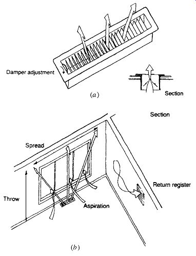
FIG. 34 The typical floor register (diffuser) in its 2¼-in. × 12-in. (60-mm
× 300-mm) size (a). It has diverting vanes for spread and an adjustable damper.
See TABLE 5 for characteristics. (b) Spread and throw; cooler room air is
induced by aspiration to join the stream of warm air, resulting in a bland,
pleasant air stream that crosses the room.
8. HEATING/COOLING SYSTEMS
Mechanical cooling is a much more recent development than heating; in its early days, it was widely adopted as a retrofit to existing heating systems.
The first two approaches to mechanical cooling that follow reflect this early attitude.

TABLE 5 Typical Residential Forced-Air Register, 2¼ × 12 in. (60 × 300 mm)
(a) Cooling Coils Added to Warm Air Furnaces
This common system utilizes a rather simple arrangement of the refrigeration cycle. FIG. 1 illustrated the circuit of a refrigerant in compression, condensing, and evaporation, in which the condenser heat is carried away by water and the evaporation process draws heat out of water in another circuit to produce chilled water. Thus, the heat is moved to a heat-rejection location outdoors.
FIG. 35 is a schematic diagram of an air-to air (in contrast to a water-to-water) refrigeration device. Air instead of water can be used to cool the condenser, and indoor air can be cooled directly by being passed over the evaporator coil in which the refrigerant is expanding from a liquid to a gas.
Thus, heat is moved from the indoor air to the out door air by the step-up action or heat-pumping nature of the refrigeration cycle. When indoor air is cooled directly in this manner, by the expanding refrigerant, the process is usually known as direct expansion. The cooling coils therefore are often referred to as DX coils. FIG. 36 shows another popular arrangement in which the airflow through the furnace and coils is horizontal.
Meanwhile, the compressor-condenser unit is placed outdoors on a concrete slab or on the roof. The unit creates a noisy, hot microclimate in summer- an influence on both site and building planning.
(b) Hydronic and Coils
This system combines a perimeter hot water heating system with an overhead air-handling system. A boiler with a tankless coil supplies domestic hot water. The boiler's heat output supplies both the perimeter loop and a coil in the air-handling unit of the duct system. The total heating load is met by the combination of radiant heat generated by the perimeter loop and heated air from the overhead air-handling system.
As installed in the Levittown standardized houses, the perimeter loop consists only of ½- or ¾-in. (13- or 19-mm) tubing embedded 4 in. (100 mm) below the top of the floor slab to overcome the cold slab effect. It has the capacity to maintain a 35Fº (19Cº) differential between the inside and outside temperatures at the perimeter.
The air-handling unit and overhead duct sys tem, incorporating supply outlets in each room and central return, is used throughout the year.
Its cooling coil is connected to an adjacent outdoor condensing unit (FIG. 37).
Because the heating load is shared by the slab loop and by warm air, the winter indoor temperature remains fairly constant. The air can be distributed at no more than about 120ºF (49ºC), or 20Fº (11Cº) less than with a conventionally ducted system.
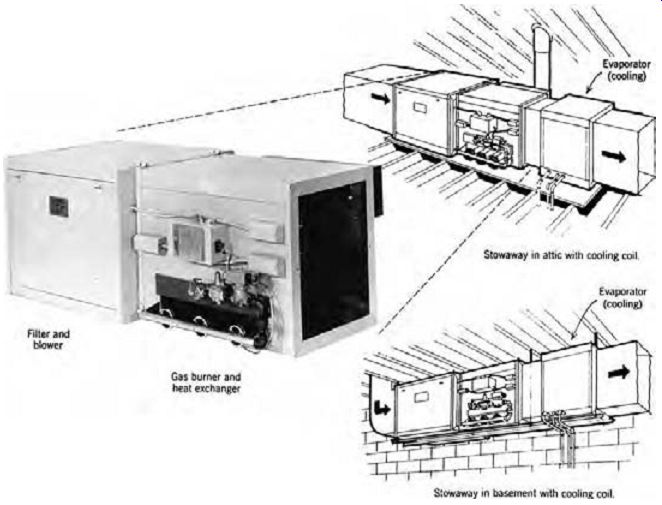
FIG. 36 Compact horizontal flow combinations for forced-air heating and
cooling. The small pipe between the two refrigerant pipes of the cooling unit
is a water drain that carries away the condensed moisture from the recirculated
and outdoor air. The heating unit requires gas and flue or exhaust gas connections.
Refrigerant pipes connect to the outdoor compressor-condenser unit.
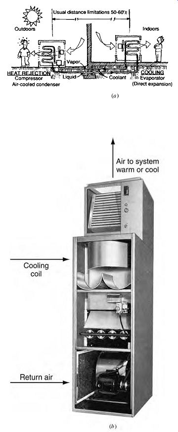
FIG. 35 The compressive refrigeration cycle (a) used in an exterior air-cooled
heat-rejection unit and an interior cooling coil suitable for placement in
a central airstream. (b) Cooling/heating air-handling unit. Cutaway view shows
an upflow air pattern.
At the lower left is the return air intake and a filter; adjacent are the fan and motor. Above these components are the gas burning elements. At the top is the direct-expansion cooling coil.
(c) Air-Air Heat Pumps
These use the refrigeration cycle to both heat and cool, thus eliminating the distinction between furnace (or boiler) and DX cooling coils. As shown in FIG. 38, heat is "pumped" from indoors to out doors in summer (FIG. 38a) and from outdoors to indoors in winter (FIG. 38b). Heat pumps can transfer heat air-air, air-water, and water-water. The most common application for smaller buildings is the air-air heat pump, shown in Figs. 9.38 and 9.39.
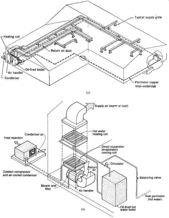
FIG. 37 Combination hydronic and forced-air system (a) using a perimeter
hot water loop in the floor slab and an overhead air supply. (b) Close-up of
the heating and cooling components.
The boiler heats both the slab perimeter and the coils in the airstream.
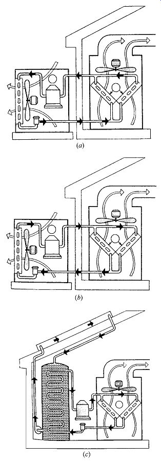
FIG. 38 Heat pump applications of the compressive refrigeration cycle. The
simple air-air heat pump provides cooled air (a) or heated air (b). Teamed
with a solar collector and water storage tank (c), the heat pump can yield
usefully warm temperatures in the airstream while increasing the collector
efficiency by lowering the storage tank temperature.
In a single-package (also called unitary) system (FIG. 39a), only one piece of equipment is involved.
A single-package air-air heat pump moves heat between an outdoor air stream and an indoor air stream; although kept separate, both streams pass through a single outdoor unit. A system with both outside and inside components is called a split sys tem (FIG. 39b). A split-system air-air heat pump moves heat via a refrigerant loop between the out door unit (which also contains the compressor), through which outdoor air passes, and the indoor unit (which usually contains backup heating coils) for the treatment and circulation of indoor air.
Single-package heat pumps are commonly located on roofs, where they have unlimited access to outdoor air, and where their noise is less likely to annoy-provided they are sufficiently isolated from the building's structure. This approach is shown in the day-lighted, passively solar-heated Mount Airy, North Carolina, library (FIG. 40). This 14,000-ft^2 (1300-m^2) building also has a solar preheating sys tem for its hot water. The five air-air heat pumps utilize economizer cycles (up to 100% outside air when temperatures are favorable). The average annual building energy consumption has been monitored at about 17,000 Btu/ft^2 (53,635 W/ m^2)--approximately one-third of nearby similar function buildings.
Individual air-air heat pump units are especially common in building types with all-perimeter spaces with varying orientations and numerous thermal zones. Motels are a prime example. In FIG. 41, separate air-air heat pumps serve each motel room; at best, their constant noise helps mask the intermittent sounds from the adjacent parking lot/circulation space. Opportunities for heat exchange between these heat pumps are scarce; if a central water loop were substituted for outdoor air as the heat source/sink, energy costs would go down, although the first cost would rise.
Split systems are popular because the noise of the compressor and the outdoor air fan are removed from the interior, and the size of the indoor unit can be quite small. This indoor element is often mounted either high on the wall or on the ceiling. Such an indoor unit is available with automatically changing louvers; when it is in the cooling mode, it delivers cool air along the ceiling, from where it sinks to the level of occupancy; cold air blowing directly on people is avoided. In the heating mode, the louvers shift to direct hot air steeply downward. The greater the distance between the indoor and outdoor units, the greater the strain on the refrigerant loop.
Heat pumps have a high initial cost, and they have in the past shown a relatively high frequency of compressor failure. Noise from the compressor and the outdoor air fan may affect site planning, especially for residences.
One of the primary attractions of the heat pump is that in its heating mode it can deliver more energy than it consumes (electrically). Although energy (usually electricity) is required to run the cycle, the pump draws "free" heat from a source such as out door air. The total heat delivered to the building is more than the heat (electricity) required to run the cycle. The measure of this heat advantage is called the coefficient of performance (COP), defined as COP = heat delivered to space/necessary work input. In typical space-heating applications, a seasonal COP of 2 or more is common in mild-winter areas. Because the COP changes with outdoor conditions and indoor load, a seasonal energy efficiency ratio (SEER) rating system has been established.
SEER measures the number of Btu/h removed for each watt of energy input, averaged over the cooling season. The higher the SEER, the more efficient the heat pump's seasonal performance. SEER ranges are roughly as low as 5 and as high as 15. The heating cycle of the heat pump has a similar rating sys tem, called the heating seasonal performance factor (HSPF).
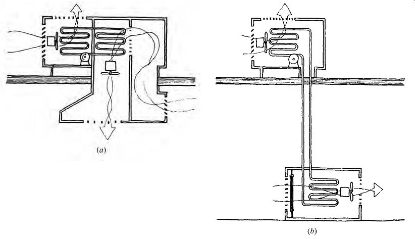
FIG. 39 The package unit (a) and the split system (b) are popular applications
of the air-air heat pump. The package unit and the outdoor unit of the split
system are also typically placed outside walls, as well as on roofs, as shown
here.
As might be expected from a device that draws heat from winter outdoor air, there are limitations to its heating performance. As outdoor temperatures approach 32ºF (0ºC), the COP drops and the outdoor coil tends to ice over. Built-in electric resistance coils must then be used; this, of course, ends the efficiency advantage that made the heat pump attractive. See FIG. 42 for a demonstration of falling performance with falling temperatures. Because of this characteristic, air-air heat pumps are less frequently used in cold-winter climates. They also generally make questionable backup choices for passively solar-heated buildings in colder climates, because backup sources are typically needed only in the coldest weather.
FIG. 40 Mount Airy Library, Mount Airy, North Carolina. Mazria/Schiff & Associates,
Architects. (a) View from the southwest. (b) Plan.
(c, d) North-south sections relate sunlight and natural heat flow. Individual
package heat pumps are set on the flat-roof sections.
Heat pumps that pump heat from water sources, such as wells or solar-heated storage tanks, or from the ground, are much more depend able cold weather performers. Water-air heat pumps (shown in FIG. 38c) and solar collectors make an effective team. As these rather high-COP heat pumps remove heat from the solar storage tank (to deliver it to the indoor air), the resulting lower temperature of the solar-heated water increases the solar collector's performance. (See Fig. 21.36 for solar collector efficiencies.) Assume that on a cold, partly sunny day, the collector being fed water from the tank at 90ºF is able to raise its temperature by 4ºF to 94ºF (from 32ºC to 35ºC). This improvement is slight because of the rather high heat loss that a 94ºF collector experiences when surrounded by cold air. If, however, the collector were to be fed 59ºF (15ºC) water, its heat loss would be greatly reduced. The heat that the collector does not lose to the cold air can be invested in the 59ºF water, which will thus leave at a considerably higher temperature than 59ºF + 4 = 63ºF. Thus, more solar energy is collected, and more is available for transfer to the building via the heat pump. The heat pump, in turn, can heat the 59ºF tank water to much higher temperatures to serve the coils in the air-handling unit.
Although most of today's heat pumps utilize electricity to drive the compressive refrigeration cycle, there are also absorption cycle heat pumps that utilize natural gas. The GAX heat pump (FIG. 43) not only uses this lower-grade resource for heating and cooling, it avoids CFCs and HCFCs and functions at outdoor temperatures much lower than those of the electric air-air heat pump. Eventually, solar energy can be used to drive the absorption cycle. Solar-driven refrigeration is a particularly elegant blend of energy source and task-the hotter the sun, the higher the cooling capacity.
(d) Ground Source Heat Pumps
Ground-air heat pumps, also called geothermal heat pumps or geo-exchange systems, are found in several configurations throughout North America. They often provide domestic hot water in addition to heating and cooling. An environ mentally safe refrigerant is circulated through a loop installed underground (or in a pond or lake), taking heat from the soil in winter and discharging heat to the soil in summer. The loop is often high-density polyethylene (HDPE). Below the surface, soil temperatures are more stable year-round than outdoor air temperatures, thus raising the COP relative to that of air-air heat pumps. Annual well-water (deep soil) temperatures were shown in Fig. 8.56. This system is almost completely out of sight, with no maintenance or weathering of exterior equipment.
Noise is confined to the compressor in a small indoor mechanical room.
Some common configurations are shown in FIG. 44. In the closed systems (a-c) the flow rate is typically 2 to 3 gpm/ton of refrigeration (0.3 to 0.5 mL/J), with lower flows in the open loop systems.
FIG. 41 Air-air heat pumps serve a motel. (a) A panel set just forward of
the exterior wall allows the heat pump to inhale and exhale outdoor air around
the panel edges. In summer it discharges warm air; in winter, cool air. (b)
Interior cabinet contains the heat pump.
Room air is taken in as shown, then discharged (after cooling or heating) upward across the glass surface-the likely point of maxi mum heat loss or gain.
The horizontal ground source closed loop heat pump (FIG. 44a) requires trenches 3 to 6 ft (1 to 2 m) deep; typically, 400 to 650 ft (120 to 200 m) of pipe are installed per ton (12,000 Btu/h or 3.5 kW) of heating and cooling capacity. To squeeze more pipe length into a trench, a "slinky" coiled pipe is sometimes used. The trenches can be placed below parking lots or lawns and gardens.
The vertical ground source closed loop heat pump (FIG. 44b) is particularly applicable where the site area is limited. Vertical holes are bored from 150 to 450 ft (46 to 137 m) deep. Each hole contains a single full-depth loop and is backfilled (or grouted) after the loop is installed. Because the summer temperature is much lower at greater depths, less pipe length is required than for horizontal loops.
The distance between boreholes varies from a mini mum of 15 ft (4.6 m) with high water table and low building cooling loads to as much as 25 ft (7.6 m) for buildings with high cooling loads. A minimum distance of 20 ft (6 m) is usually recommended.
The pond or lake closed loop heat pump (FIG. 44c) is sometimes used when a building is close to an adequately large body of water. The loop is submerged, and the surrounding water conducts heat far more rapidly than does soil. The resulting shorter length required, and the low cost of placing the coils in water, can make this attractive. How ever, the water level in the pond should never drop below a minimum of 8 ft (2.5 m) and must have sufficient surface area for heat exchange.
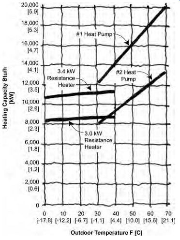
FIG. 42 Typical air-air heat pump operating characteristics; heat delivery
falls with falling outdoor temperature.
FIG. 43 An air-cooled advanced GAX (generator-absorber heat exchange) heat
pump uses aqua ammonia as the absorbent and is operational down to -10ºF (-23ºC).
The target cooling COP is 0.95; heating COP is 1.55. Designed for light commercial
applications, it ranges from 5 to 25 tons capacity. (RHX = refrigerant heat
exchanger; IP ABS = intermediate pressure absorber.)
The groundwater-source open loop heat pump ("pump and dump") is suitable only where ground water is plentiful, and may be prohibited by local codes and environmental regulators. One variant of this system (FIG. 44d) takes water from one well, through a heat exchanger within the building, then discharges it to a second well. Another vari ant (FIG. 44e) takes water from the bottom and discharges back into the top of the same (standing) well, typically 6 in. (150 mm) in diameter and as deep as 1500 ft (460 m).
The Wildlife Center of Virginia at Waynesboro is a wildlife teaching-research hospital. Its 5700-ft^2 (530-m^2) floor area is served by four geothermal heat pumps (two at 4 tons, two at 5 tons) connected to 11,350 ft (3460 m) of underground horizontal pipe, laid in a "slinky" configuration and thus fitting within about 2500 ft (760 m) of trench. The trench was dug around existing trees and placed under future roadways in its forest setting. Energy simulations estimate that annual heating, cooling, and hot water will use about 35,000 kWh. Had air-air heat pumps and an electric water heater been used instead, the estimate is 66,000 kWh, a 47% yearly savings advantage for the geothermal system.
Ground source heat pumps are often used in retrofits, especially in schools where site areas are plentiful, or historic structures where small-size interior mechanical equipment is highly desirable.
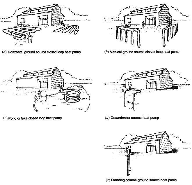
FIG. 44 Configurations
of ground source heat pumps. (a) Horizontal ground source closed loop heat
pump laid in trenches. (b) Vertical ground source closed loop heat pump placed
in boreholes. (c) Pond or lake closed loop heat pump. (d) Groundwater source
heat pump taking water from one well and discharging it to another. (e) Standing
column groundwater source heat pump taking water from, then discharging to,
the same well.
The Daniel Boone High School near Johnson City, Tennessee, was built in 1971 with a two-pipe chilled water system and electric resistance heat.
A 1998 ASHRAE Technology Award was won when this 160,000-ft^2 (14,864-m2) school was retrofitted with a ground source vertical closed loop heat exchanger that is fed by 320 boreholes, each 150 ft (46 m) deep. Each borehole loop is 300 ft (91 m) of ¾-in. (19-mm) polyethylene pipe. The boreholes are arranged in sections of 20 holes each. The holes are 15 ft (5 m) on center. The 20-hole sections are separated by 20 ft (6 m). The loops all connect to an 8-in. (203-mm) supply and same size return line to the new heat exchanger within the existing mechanical room. Within the building, a new water loop heat pump system is installed, one heat pump in each zone.
(e) Water Source Heat Pumps
The school described previously uses an interior closed water loop that connects all the heat pumps of all thermal zones. This system facilitates heating in one zone while another zone is being cooled, because simultaneous heat "deposits" and heat "withdrawals" actually help the system to function most efficiently. FIG. 45 diagrams the typical water loop system, where a supplementary heat source (such as a boiler) for cold weather, and a supplementary heat rejector (such as a cooling tower) for hot weather, are installed to maintain usable water temperatures within the loop. A large office building in Pittsburgh that uses such a system is shown in Fig. 10.63.
Motels are good candidates for water loop heat pumps, because some rooms face sunny conditions, others are shaded; some are occupied, some unoccupied; and substantial domestic hot water needs all combine to make a heat-sharing water loop attractive.
9. PSYCHROMETRICS AND REFRIGERATION
The procedure for sizing cooling equipment is more complicated than for heating because latent as well as sensible heat must be considered. The example following refers to the psychrometric chart; a review of Figs. 8.35 to 8.42 may be helpful.
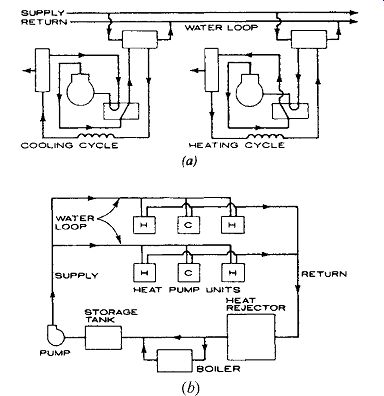
FIG. 45 Water source heat pumps. (a) Each water-air heat pump either deposits
heat into the loop (while cooling) or with draws heat (while heating). This
system is particularly well suited to buildings where simultaneous heating
and cooling needs occur. (b) Supplementary heat sources (boilers) and heat
rejectors (cooling towers) are usually provided.
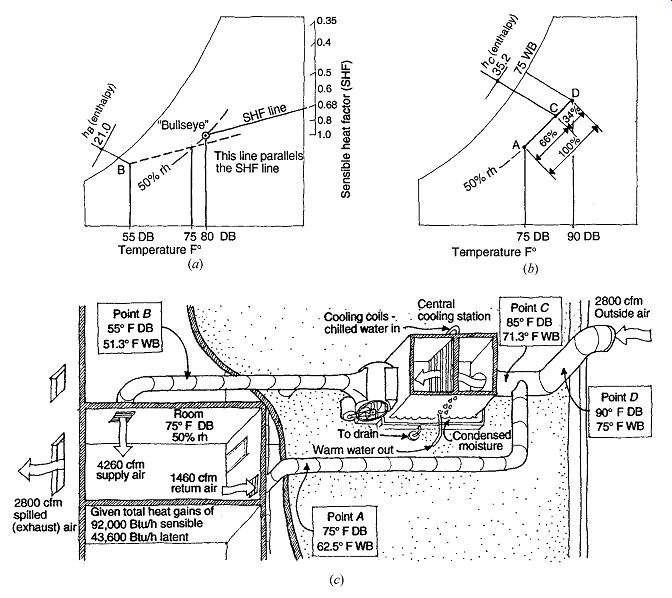
FIG. 46 Sizing cooling equipment using the psychrometric chart (see detailed
charts in Section F). (a) Finding the conditions for the supply air. SI values
are: 12.8, 23.9, and 26.7°C DB. (b) Finding the conditions for the return air-outdoor
air mixture. SI values are: 23.9 and 32.2°C DB; 23.9°C WB. (c) Points A, B,
C, and D, shown within the building and its cooling equipment. SI values are:
Point A (23.9/16.9°C); point B (12.8/10.7°C); point C (29.4/21.8°C); point
D (32.2/23.9°C); outdoor air (1321 L/s); exhaust air (1321 L/s); supply air
(2010 L/s); return air (689 L/s); room (23.9°C).
References and Resources
AIA, Ramsey, C. G., and H. R. Sleeper. 1994. Architectural Graphic Standards, 9th ed. Wiley. New York.
ASHRAE. 2009. ASHRAE Handbook-Fundamentals.
American Society of Heating, Refrigerating and Air-Conditioning Engineers, Inc. Atlanta, GA.
ASHRAE. 2007. ANSI/ASHRAE/IESNA Standard 90.1-2007: Energy Standard for Buildings Except Low-Rise Residential Buildings. American Society
of Heating, Refrigerating and Air-Conditioning Engineers, Inc. Atlanta, GA.
ASHRAE. 2007. ANSI/ASHRAE Standard 90.2 2007: Energy-Efficient Design of Low-Rise Residential Buildings. American Society of Heating, Refrigerating and Air-Conditioning Engineers, Inc. Atlanta, GA.
Barden, A. A., and H. Hyytiainen. 1993. Finnish Fireplaces: Heart of the Home, 2nd ed. Finnish Building Centre, Ltd. Helsinki.
Bourne, R. and M. Hoeschele. 1998. "Performance Results for a Night Roof Spray Storage Cooling System," in Proceedings of the 23rd National Passive Solar Conference. American Solar Energy Society. Boulder, CO.
Calm, J. E. 1994. "Refrigerant Safety," in ASHRAE Journal, July.
Hydronics Institute Division of GAMA. 1996. Installation Guide for Residential Hydronic Heating Systems, No. 200. Berkeley Heights, NJ.
Mozer, M. 1998. "The Neural Network House: An Environment That Adapts to Its Inhabitants," in Proceedings of the American Association for Artificial Intelligence, Spring Symposium on Intelligent Environments. March 1998. Stanford University. Palo Alto, CA.
Natural Gas Cooling Equipment Guide, 4th ed. 1996.
American Gas Cooling Center. Arlington, VA.
The New Buildings Institute. "Small Commercial HVAC System Design Guide"
U.S. Environmental Protection Agency. "Energy Star Labeled Heating and Cooling Equipment"
Prev. | Next
Home Similar
articles top
of page