AMAZON multi-meters discounts AMAZON oscilloscope discounts
This Section continues the discussion that began in Section 9, with a focus now on more complex systems for larger buildings with many thermal zones. Those using this book for reference rather than as a text may have gone directly to this Section without reading the preceding material. If so, pay attention to the following comments.
Before Selecting an HVAC System for a Large Building:
The choice of an HVAC system should consider preliminary design issues that are discussed in Section 5 and sections of Section 9:
Section 5, "Indoor Air Quality," discusses the relationship between comfort, zoning, and equipment that helps maintain acceptable air quality in buildings.
9.1 "Review of the Need for Mechanical Equipment," reviews the relative thermal role of building envelopes compared to their internal heating, cooling, and ventilating systems.
9.2 "Heating, Ventilating, and Air Conditioning (HVAC): Typical Design Processes," outlines the decisions made by the architect and the engineer.
9.5 "Refrigeration Cycles," reviews both the compressive and the absorptive refrigeration processes.
At the onset of the twenty-first century, large building HVAC is showing several trends. One is the increasing willingness to let mechanical equipment share its tasks with natural ventilation and day lighting. Building automation has made this easier to manage. Another trend is toward an underfloor plenum air supply (related to, but not identical to, displacement ventilation approaches commonly used in critical-environment facilities) rather than using ducts connected to diffusers and return grilles, both on the ceiling. Concern about air quality indoors and the environment outdoors is producing a variety of approaches to increased ventilation effectiveness.
Refrigerants containing CFCs and HCFCs are being avoided. Fuel cells and photovoltaics are promising increased energy autonomy to larger buildings.
1. HVAC AND BUILDING ORGANIZATION
By this time, many decisions about a building's design have been made: design strategies appropriate to the climate and the building's activities have been identified, and the basic siting and overall form of the building have been determined from daylighting and thermal considerations, among others. This section begins by considering the internal yet broad issues of zoning and system choice and ends with a discussion of the more detailed consequences of sys tem choice. A general guide to estimation of a building's thermal zone requirements was presented in Section 8.2, which discussed the importance of differences in function, schedule, and orientation.
(a) Zoning
The minimum number of thermal zones for a conventionally designed multipurpose building is shown in Fig. 1. A need for more than these 16 zones could result from differences in scheduling within a zone, such as between offices and stores. As is true of the other occupied floors, apartments have a minimum of five zones (based on orientation); however, the emphasis on individual controls-and the variation in usage patterns- often produces as many zones as there are apartments. When the details of zoning are added to the other preliminary design decisions, the details of HVAC systems can be considered.
(b) System Anatomy
Table 1 describes the basic organization of any HVAC system. Three kinds of common tasks (heating, cooling, and ventilating) are done by production components; usually, they require distribution and delivery components. Intake supplies and exhaust by-products accompany each task.
Although the eventual choice of HVAC system should follow an analysis of the zone's needs, some early concepts underlie system choices.
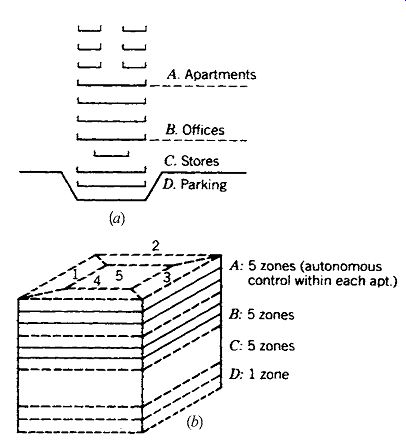
Fig. 1 The minimum number of thermal zones for a rather large, conventionally
designed, multipurpose building.
(c) Central versus Local Systems
Central systems require one or several large mechanical spaces (often in basements and/or on roofs), sizable distribution trees, and complex control systems. The noise, heat, and other characteristics of such mechanical rooms can be controlled fairly easily, because the machinery is concentrated at a few locations. Similarly, maintenance is easy to perform without interrupting normal activities, although breakdowns in central equipment can paralyze the entire building. Air quality can be controlled by locating the air intakes high above the pollution at street level and by regular maintenance of the centralized air-filtering equipment. Longer equipment life can be expected with regular maintenance. Energy conservation can be served by the recovery of one machine's heat by-product for a nearby machine's heat input.
Although there are many ways to provide for the differing thermal needs of the many zones served by central systems, one important drawback of central systems is the size and length of the distribution trees necessary to carry centralized ser vices to many local receivers. Another drawback s a difference in zone scheduling: when the entire system must be activated to serve one zone (such as computer operations in an office building on a weekend), energy is wasted.
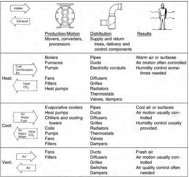
Table 1 Basic HVAC Systems: Tasks and Components
Local systems therefore become increasingly attractive as scheduling differences multiply. Also, pronounced differences in other factors-function (with resulting comfort expectations) or placement within the building, for example-can lead to the choice of local systems. Large and central zed equipment spaces are not required with focal systems; rather, production equipment is distributed throughout the building (or over the roofs of low-rise structures). Dispersal of equipment minimizes the size of distribution trees and greatly simplifies control systems. Moreover, sys tem breakdowns affect only small portions of the building. However, noise and other by-products of multiple machines pose numerous potential threats to occupied spaces, and maintenance is demanding, because access to so many separate locations is often disruptive or constricted. Then, too, air quality depends on the regular cleaning of many filters scattered over the building, often within occupied spaces. The potential for energy conservation seems promising, because heating or cooling is produced only as locally needed, but there is little chance to use one zone's waste heat as another's needed source.
Central heat/cool, local air distribution has become a popular way to take advantage of the favorable characteristics of both central and local approaches. This is shown in Fig. 2b, with a central boiler/chiller space remotely located and fan rooms on each floor. This minimizes the bulky distribution tree for air; although the distribution tree for heated and chilled water is extensive, it is also of much smaller diameter and therefore is relatively easily accommodated. The central equipment room makes energy recovery systems from boilers and chillers more feasible.
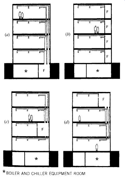
Fig. 2 Fan rooms (F) can
either be combined with or separated from boiler/chiller "equipment" rooms
(*). (a) Common location for a central combined equipment room. (b) Increasingly
common arrangement of a small fan room on each floor, with an equipment room
in the basement. (c) An intermediate floor may be able to provide space for
a central fan room, while the heavier and noisier equipment remains in the
basement. (d) With a top-floor central fan room, the equipment may be located
either on the roof or in a mechanical penthouse, or may remain in the basement.
(d) Uniformity versus Diversity
How similar should the interior environments of buildings be? This question encompasses not only thermal experiences, but visual and acoustical ones as well.
The advantages of uniformity are most evident in a rapidity of design and construction that, through mass production and speed, often brings lower first costs. Uniformity of ceiling heights, light fixture placement, grille locations, and so on promotes flexibility in office arrangements that can extend a building's usable life span. However, there are at least four types of offices, which may need to be interchangeable within such "flexible" space.
The typical enclosed office has the privacy of four walls and a door. The bullpen office has repeated, identical workstations, with low dividers at about the height of the desk surface. The uniform open plan office resembles the bullpen, but with higher divider partitions for added privacy. The free-form open plan office has some individually designed workstations with divider partitions of varying heights (sometimes reflecting the varying status of workers). In the bullpen and uniform open plan office, the resulting uniformity is not always attractive to users, and diversity is often encouraged at a more personal level-with office furnishings, for example. A more thorough approach to diversity can provide stimulus to the user who spends many hours away from the variability of the exterior climate.
If offices must be uniform in ceiling lighting, air handling, and size, the corridors that connect them and the lounges or other supporting service spaces can deliberately be made different. Diversity requires a complete and detailed design of places; it gives the builder a more complex and interesting task; and it can provide orientation and interest to the users. The attractiveness of diversity is evident in most collections of retail shops, in which light and sound-and sometimes heat and aroma-are used to distinguish one shop from the next.
Diversity in the thermal conditions to be maintained, such as warmer offices and cooler circulation spaces in the winter, can be used to enhance the comfort of the office users. Designers have long recognized that a space can be made to seem brighter and higher if it is preceded by a dark, low transition space. Thermal comfort impressions can be manipulated similarly. Less than comfort able conditions in circulation spaces or other less critical zones not only make the critical spaces seem more comfortable by contrast, but also save significant amounts of energy over the life of a building. Furthermore, such conditions can make passive strategies more attractive.
A large-scale demonstration of diversity in thermal zones is shown in Fig. 3. Passive solar heating can make a significant contribution, even through a shallow-sloped, single-glazed cover in cloudy Glasgow, Scotland, largely because the mall area and leisure areas are allowed a much wider thermal range than would be permitted in stores and offices. The overcast skies are quite suitable for daylight, and the addition of summer sunshading makes natural ventilation (through the stack effect, assisted by fans) possible during the cool summers. U.S. Pacific Northwest climate conditions are similar.
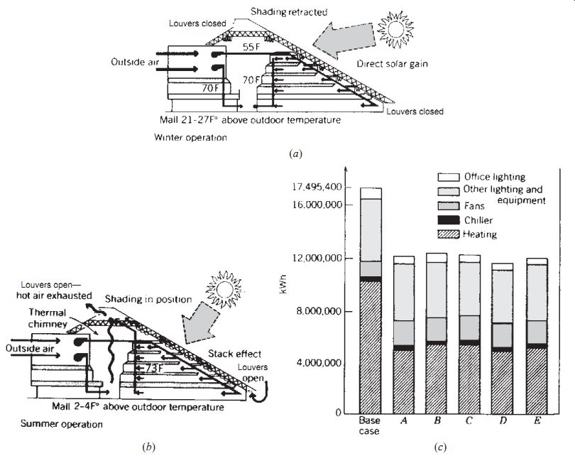
Fig. 3 St. Enoch's Square, Glasgow, Scotland: a proposal to use passive
solar heating, daylighting, and natural ventilation. Reiach & Hall and
GMW Partnership, architects (joint venture); Cosentini Associates, energy consultants;
Princeton Energy Group, daylighting consultants. (a) Schematic section showing
winter operation; the mall temperature varies around 63ºF (17ºC) during operating
hours, while offices are kept near 70ºF (21ºC). (b) Schematic section showing
summer operation; the mall temperature varies from about 68 to 74ºF (20 to
23ºC) during operating hours. (c) Estimates of annual energy consumption for
a conventional-design base case and several alternative configurations. Note
the significantly lower heating energy requirements, resulting in part from
the lower winter temperatures allowed for the less-critical zones such as the
mall and the leisure areas in configurations A to E.
(e) Comparing Systems and Zones
In the process of selecting systems from among the wide variety available, it is helpful to consider the match between the zones' characteristics and those of various systems. Among the considerations are zone placement (close to or away from the building skin), the zone's thermal loads, the comfort determinants based on the zone's activities, the space available for system components within the zone, and the life-cycle costs of various system alternatives.
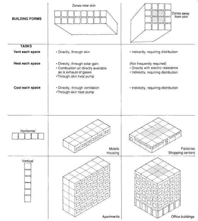
Fig. 4 Zone placement
and building form are related to heating, cooling, and ventilating tasks; some
applications take on typical building forms. ( University of Oregon.)
Zone placement will sometimes preclude local systems, which depend on easy access to outdoor air both for fresh air and for a heat source or sink.
Local systems for interior (away-from-skin) zones are awkward. Relationships between zone placement and building forms are shown in Fig. 4.
The thermal loads on each zone determine the extent to which heating or cooling is the dominant problem-which, in turn, can influence the choice of system. A zone with little cooling load and low moisture production may be well served by a simple system of fresh air plus heating, with no humidity control. Zones that require cooling will usually also require more complete control of air motion and relative humidity. Although it is risky to generalize about which comfort determinants are most important (given the differences between activities and between individuals), it can generally be assumed that comfort and thermal tasks are related.
Thus, the choice of systems can be based partly on whether the system provides good control of the more important comfort determinants.
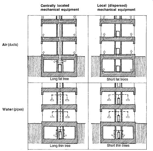
Fig. 5 Matrix of distribution trees.

Table 2 Procedure for Matching Zones and Systems
(f) Distribution Trees
How many, what kind (air or water), and where should HVAC distribution trees be placed within buildings? HVAC system choice is influenced by the amount of space the system requires. In some cases, it is easy to provide small equipment rooms at regular intervals throughout a building, such that little or nothing in the way of a distribution tree will be required. In other cases, a network of distribution trees and central, large equipment spaces are easier to accommodate. These central systems typically fall into one of three classifications:
All-air (the largest distribution trees)
Air and water
All-water (the smallest distribution trees, with local control of fresh air)
The details of these systems can be found in Sections 10.5 to 10.7, along with typical applications and space requirements. Figure 10.5 shows the matrix of central-local, air-water influences on distribution trees.
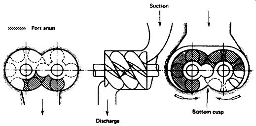
Fig. 6 The Fox Plaza Building, San Francisco. Victor Gruen Associates,
Inc., architects and engineers. (a) Elongated façade facing northeast shows
the 16 floors of apartments above, the 10 floors of offices below, and the
13th-floor mechanical space. In that space are chillers, and pumps for cooling
tower water and chilled water, as well as boilers and converters (steam to
hot water) for the fan-coil units in the residential stories above and hot
water coils in the office stories below. Air handling for the offices is also
located here, down-fed by high-velocity ducts. Residences are heated; offices
are heated and cooled. (The roof has the cooling tower and the domestic hot
water generator-storage units for the residential stories.) (b) Construction
photo with air-handling units visible on the 13th floor, and downfeed ducts
that supply high-velocity hot and cold air to the office floors.
A simplified procedure for matching zones and systems is shown in Table 2, in which preliminary system choices are made for a building such as the multipurpose structure shown in Fig. 1. In this process, the original 16 zones are translated into three local systems and three central systems: one all-air, one air and water, and one all-water.
The Fox Plaza Building in San Francisco, which illustrates many of the matches between systems and zones, is shown in Fig. 6. This project includes four major building types in one structure:
1. Underground garage for the storage of cars
2. Commercial center at ground level, including a bank, a women's specialty store, and other commercial establishments
3. Ten floors of offices
4. Sixteen floors of apartments
The mechanical level is located between the office portion of the building and the apartments above.
The distribution trees-heating, air conditioning, electrical, and so on-are thus directed both upward and downward, resulting in two shorter trees rather than one longer tree. The spatial requirements of offices and those of apartments are quite different; thus, the floor-to-floor heights, window treatment, and heating, cooling, electrical, elevators, and other services are different. The placement of the mechanical level between the offices and the apartments also provides for a definite visual separation between the two functions.
Quite unusual is the placement of the steam boilers on the 13th floor instead of in the conventional basement location. Only a small amount of auxiliary equipment is located on the roof and in a small portion of the garage. Residential areas have hot-water heating (residential cooling being rarely needed in San Francisco), offices have dual duct, high-velocity heating/cooling, and commercial (ground-floor) tenants are supplied with hot and chilled water for individual climate control requirements.
(g) Central Equipment Location
The Fox Plaza Building has an intermediate location for the heating and cooling production equipment-one that separates floors of apartments from floors of offices. Other typical locations for central equipment are in the basement (where machine noise is most easily isolated, utilities are easily accessed, and machine weight is little problem) and on the roof, where access to air as a sink for reject heat is easiest of all, and headroom is unlimited.
Very tall buildings may require several intermediate mechanical floors. Examples of these approaches are found throughout the rest of this Section.
The equipment's considerable heat, moisture, air motion, noise, and vibration potentially annoy occupants on nearby floors (or even neighboring buildings). As shown in the Fox Plaza example, the equipment placement can be expressive of building services and can play a useful demarcation role between vertical layers of high-rise buildings. Moving the equipment off the roof also frees this prestigious view location for high-rent occupancy and allows a roof form much more expressive of great height than a flat roof with a cooling tower.
(h) Concealment and Exposure
The pipes, ducts, and conduits that take the necessary resources to and from the interior are often carried within a network of spaces unseen by anyone except builders and repair people. The advantages of concealment include less noise from moving water and air, fewer surfaces requiring cleaning, less care necessary in construction (leaks, not looks, are important), and more control over the appearance of the interior ceiling and wall surfaces. Although maintenance access to such hidden supply lines is more difficult, various types of readily removable covers are available, particularly in suspended ceilings.
However, the exposure of these supply net works provides an honest and direct source of visual (and occasionally acoustical) interest. Exposure in corridors and service areas and concealment in offices constitute an approach used in many office buildings. Flexibility is usually encouraged by expo sure; changes can be easily made when there is no need for neatly cut holes in concealing surfaces.
However, flexibility from full-height movable partitions requires constant ceiling heights-a feature of the suspended-ceiling approach.
One of the more spectacular examples of exposed mechanical (and structural) systems is shown in Fig. 7--the result of a design competition for a museum of modern art, reference library, center for industrial design, center for music and acoustic research, and supporting services in down town Paris.
When users are invited to play an active role in adjusting conditions inside, exposure of the switches they manipulate is helpful. Visible mechanisms not only remind users of their opportunities but also encourage user interaction. In this way, adjustments are sometimes discovered that the designer had not anticipated.
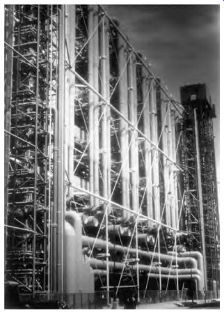
Fig. 7 Centre Georges Pompidou, Paris. A view of the mechanical support
systems. Piano + Rogers, architects.
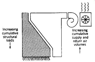
Fig. 8 Distribution trees: with rooftop centralized air handling, the supply
and return air duct sizes decrease as they approach the ground. Conversely,
the structural load increases toward the ground.
(i) Mechanical-Structural Integration or Separation
The similarity of these two technical support systems-structures and environmental controls- has intrigued designers ever since mechanical systems began to require substantial volume for distribution, as in air-duct systems. As the complexity and size of the mechanical distribution systems was increasing with technological development (typically, more air is required to cool a space than to heat it because of a lower delta_t), the increased strength of materials was reducing the size of the structural system. The uncluttered floor areas between the more widely spaced columns became desirable for flexibility in spatial layout. With the mechanical systems at or within these columns, floor areas remained clear, thus giving mechanical-structural integration further impetus. With the new expectations for cooling, the refrigeration cycle's cooling tower often moved to the roof, often taking the air-handling machinery with it. This further encouraged the merging of systems, for one system was growing wider as the other diminished (Fig. 8). Thus, a fixed-column cross section, consisting mostly of the structural column at the base and the air duct at the top, became possible.
Yet the functions of these systems differ widely: compared to the dynamic on-off air, water, and electrical distribution systems, the structural sys tem is static-gravity never ceases. The moving parts in mechanical systems need maintenance far more frequently than the connections of structural components. Changes in occupancy can mean enormous changes in mechanical systems, requiring entirely different equipment; structural changes of such magnitude usually occur only at demolition.
Mechanical systems can invite user adjustment; structural systems rarely do. Thus, although it is possible to wrap the mechanical systems in a structural envelope, it is of questionable long-term value, given the differing life spans and characteristics of these systems.
The probability of future change suggests that the mechanical system be the exposed one, despite the appeal to many designers of the structural system's cleaner lines.
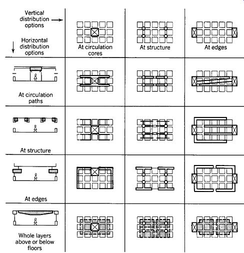
Fig. 9 Distribution tree placement options, both vertical (with impact
on the plan) and horizontal (with impact on the section). (From class notes
developed by G. Z. Brown, University of Oregon.)
(j) Distribution Tree Placement Options
These options are summarized in Fig. 9. Vertical placement options are important because they affect floor space, influencing the flexibility of spatial layout and the availability of usable (or rentable) floor space. Horizontal placement options affect ceiling height-a particular issue in daylighting design and sometimes a critical factor when overall height limits are imposed yet maximum usable floor space is desired. (In Washington, DC, for instance, no building can rise higher than the Capitol.) Both vertical and horizontal distribution at the edges can have a dramatic impact on building appearance.
The history of distribution trees and high-rise buildings is one of trends and countertrends. Initially, multistory buildings relied upon daylight and cross-ventilation, so a thin, relatively high-ceiling plan with much perimeter was favored (refer to Fig. 3.33). The heat gain and loss was all at the perimeter, so perimeter distribution trees (carrying only steam or heated water, and of quite small diameter) were generally used. As electric lighting and thus the need for air conditioning increased, so did the thickness of floor plans; large central internal areas needed a lot of forced, cooled air.
Central boilers, chillers, and fan rooms were the norm. Thus, bulky air distribution trees appeared.
At about the same time, the glass curtain wall and its slick, two-dimensional look of modernity became fashionable. The air distribution trees were so visually intrusive on the façades that they were pushed to the core, where cooling needs were relatively steady. However, the thin glass perimeter experienced extreme needs for both heating and cooling; getting from vertical trees at the core to the perimeter required larger cavities above suspended ceilings. This pushed the ceiling in the offices down to keep floor-to-floor distances economical. Vast office areas resulted that were visually dull, low-ceilinged, and without daylight.
Now, countertrends include decentralized air handling, with small fan rooms on each floor.
Vertical air distribution trees are shrinking, horizontal ones becoming more common. At the same time, daylighting is pushing office ceilings higher; so is a preference for indirect lighting and its compatibility with computer screen visual comfort.
Night cooling utilizing thermal mass is encouraging the exposure of concrete structure and favoring raised-floor air supply/ventilation systems.
A renewed interest in sun control is encouraging three-dimensional façades, replacing two-dimensional reflective glass façades (which merely redirect the sun toward someone else). With increased three-dimensionality at the façade, perimeter distribution trees are once again conceivable.
It is logical to place at the perimeter the parts of the system that deal with the effects of sun, shade, and temperature change in the several perimeter zones, leaving at the core a separate network to handle the more stable interior areas. The disadvantages of perimeter distribution include (usually) higher construction costs and an environment that is more thermally hostile due to the extremes of out door temperature.
Vertical distribution within internal circulation cores is very common, as it leaves a maximum of plan flexibility for the rest of each floor and does not disturb the prized floor areas nearest windows.
However, one centralized vertical distribution trunk will require large horizontal branches near the core, so with this choice early thought must be given to the horizontal placement options.
An unusual example of vertical air distribution at the core is shown in Fig. 10. The Fox Plaza, Los Angeles, office building's unique features include both fan rooms on each floor and a large central vertical air shaft. This air shaft begins at the bottom as a fresh air intake to each floor and tapers to become, at the top, an exhaust (heated) air outlet from each floor. Thus, the stack effect is utilized to help supply fresh and exhaust stale air from a large building, with help from small supply fans at each floor.
Vertical distribution integrated with structure creates some intriguing possibilities where the structure-HVAC integration concept is suitable. Multiple HVAC trees are implied (because there are multiple columns with which they are integrated), so the horizontal branches tend to be small. However, these branches often join the vertical trunk at the same place where critical column-to-girder structural connections need to be made; interference is common and can be costly to correct. Vertical distribution at the edges is potentially dramatic in form but costly to enclose (if outside) or wasteful of prime floor space (if inside).
Horizontal distribution above corridors is very common, since reduced headroom here is more acceptable than in the main activity areas.
Furthermore, corridors tend to be away from windows, so their lower ceilings do not interfere with daylight penetration. Because corridors connect nearly all spaces, horizontal service distribution to such spaces is also provided. Furthermore, exposure of these services above corridors can heighten the contrast between such serving spaces and the uncluttered, higher ceilinged offices that are served. Horizontal distribution at the structure is sometimes chosen, particularly where U-shaped beams or box beams provide ready channels for HVAC distribution. However, the penetration of horizontal structure members by these continuous service runs must be coordinated. Horizontal distribution at the edges can be integrated usefully with sunshading devices and light shelves; it can also act as a spandrel element that contrasts with the window strips. Horizontal distribution within whole layers below floors (or above ceilings) is often utilized, now increasingly common with displacement ventilation systems.
An example of supply at the edge for both vertical and horizontal distribution is found in the International Building in San Francisco (Fig. 11). Here the vertical shafts are prominently exposed at the corners; these shafts carry supply and return ducts serving the four perimeter air conditioning zones. Air-handling equipment and a 750-ton refrigeration plant are located on the floors just below the terrace level (those least desirable for renting). Each corner duct branches to serve two zones, which are separately controlled. Pressure reduction and blending are done by equipment in the hung ceiling, and from these points air flows to strip diffusers directly above the glass on the four sides of the building. Local controls offer comfort to personnel in each area.
Interior zones on each floor are supplied by a riser duct in the building core, which branches at each floor to a loop just outside the line of elevators. The loop serves ceiling diffusers. Between the perimeter loop and the interior loop, a return loop collects air for return to the central station (second and third floors). These return loops on the 11th to 21st floors are picked up by external return risers on alternate exterior corners. From the 10th floor down, the loops are picked up (as shown in Fig. 11) by an interior return riser that extends down through the core in front of the blank faces of the high-rise elevators. To provide a clear space between the elevator banks on the main floor (fourth or terrace), the two core ducts' risers are offset at the ceiling of that story.
In summary, perimeter air for all stories is sup plied through corner ducts. Central air for all stories is supplied through a core duct. All return air above the 10th floor is carried down through the return ducts at the other two corners. Return air from the 10th floor and below is carried down by a return duct in the core.
Further examples of the relationships among HVAC systems, their distribution trees, and buildings are given in examples that accompany the more detailed descriptions of large-building HVAC systems in Sections 10.4 to 10.7.
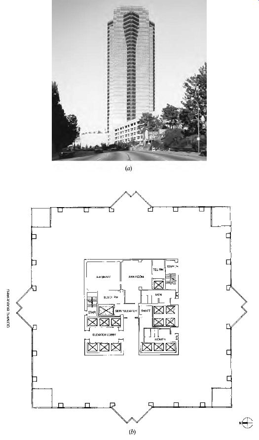
Fig. 10 The Fox Plaza, Los Angeles, office building is a 34-story, 800,000-ft^2
(74,320-m^2) granite and glass tower (a) with an unusual vertical distribution
tree. (b) Typical lower-floor plan (floors 6 to 16) shows both a fan room and
a large vertical air shaft. At this lower level, most of the shaft area is
supplying outdoor air (from an intake in the bluff face below the building);
the remainder is exhausting stale air toward the roof. Note the lack of columns
between the core and perimeter, contributing to office layout flexibility.
(c) Typical upper-floor plan (floors 31 to 33) shows fewer elevators; by this
level, most of the shaft area is exhausting stale air toward the roof. (d)
Section shows the tapered interior of the constant-cross-section central air
shaft, which relies upon the stack effect to bring in (usually cooler) outdoor
air at the base and expels hotter exhaust air at the top.
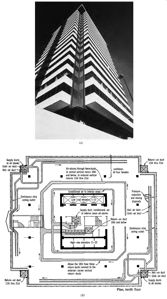
Fig. 11 The International Building, San Francisco. Anshen and Allen, architects; Eagelson, Engineers (Charles Krieger, E.E.), mechanical designers. (a) Photo of one of the four corner main duct enclosures. (b) Tenth-floor plan. Column
bay spacing is 24 ft, 6 in. (7.5 m), with a 16-ft (4.9-m) cantilever on all
four façades. The major supply ducts (both hot and cold) to all 21 floors are
located in two opposite corners. Each of these supply distribution trees serves
two adjacent sides of perimeter offices. The conditioned air is supplied from
a third-floor mechanical space. In the opposite two corners, return air from
the upper 11 floors is collected and taken down to the mechanical space. The
remainder of the return air is taken down through the core.
2. HVAC SYSTEM TYPES
Large buildings have so many thermal zones, and there are so many ways to move heat from one place to another, that hundreds of HVAC system variations have been devised. A few of the most typical are introduced in this section; the following section treats in detail the major components of HVAC production and delivery. Finally, some common variations on each of the four main system classifications are presented.
One way to classify HVAC systems is by the media used to transfer heat. Although thousands of liquids and gases can be used as carriers of heat, the three most common in building applications are air, water, and refrigerant. Traditionally, there are four main system classifications:
Direct refrigerant systems All-air systems Air and water systems All-water systems In the last three cases, the heating/cooling production equipment typically is located centrally in a large building, often rather far from the thermal zones it serves. The air-handling components may be either centrally served or served floor by floor.
Distribution tree size and placement thus become important issues when those systems are selected.
In direct refrigerant systems, the heating/cooling machine usually is located adjacent to the zone(s) it serves; thus, the machine's environment-the microclimate it creates and its needs relative to the zone's environment-becomes an important consideration.
(a) Direct Refrigerant Systems
These systems (see Section 9) nearly eliminate the distribution trees of air or water, relying instead on a heating/cooling device adjacent to or within the space to be served. Thus, they are prevalent in skin load-dominated buildings with extensive perimeter zones; these tend to be smaller buildings.
(b) All-Air Systems
The more common variations on all-air systems are shown in Fig. 12. Because air is the only heat transfer medium used between the mechanical room (central station) and the zones it serves, and because air holds much less heat per unit volume than water, the distribution trees for this class are quite thick. Sometimes, to reduce duct sizes, higher velocities are used for supply air. This generates more noise and higher friction, resulting in more energy used by fans; higher velocity should be used only sparingly, where space limitations are extreme.
For comfort, however, these systems are, over all, the best. The quantities of air moved through the central station(s) are heated or cooled, humidity controlled, filtered, and freshened with outdoor air-all under controlled conditions. Within the zones, supply diffusers/registers and return grilles allow a well-planned stream of conditioned air to thoroughly permeate all work areas. More details on air distribution are found in Section 10.4 and on this HVAC type in Section 10.5.
Single-Zone Systems. This (Fig. 12a) is the common small-building forced air-system con trolled by a single thermostat.
Single-Duct, Variable-Air-Volume (VAV) Systems. This (Fig. 12c) is the most popular large building system of recent years. Its single duct requires less building volume for distribution than do multiduct systems, and the variation of air volume flow rate (rather than of air temperature) saves energy relative to the single duct with reheat (Fig. 12e). Depending on outdoor conditions and prevailing indoor needs, the central station supplies at normal velocity either a heated or a cooled stream of air. Automatic volume controls (linked to each zone's thermostat) adjust the volume admitted to that zone within an air terminal diffuser (often located above a suspended ceiling). When the central station is supplying cold air, a zone that needs more cooling will get more air; an unoccupied room with no internal gains, or a space with heat loss through an exterior wall, will get less air. Clearly, such a system is well suited to serve the interior, always-hot zones of internal-load-dominated buildings. Less clear is its suitability for the perimeter zones of buildings in cold, cloudy conditions.
Fan-Powered VAV Systems. This variation (Fig. 12f ) allows individual units to heat when the main supply system is cooling; it might therefore serve perimeter zones. In this case, the cool air is reduced to the minimum required for acceptable indoor air quality (IAQ), and the unit's fan draws additional air from a ceiling (or floor) plenum, heating it as required.
Multizone Systems. Because each zone has an individual centrally conditioned airstream, the total distribution tree volume grows to astonishing size with only a few zones. The central station produces both warm and cool airstreams, which are mixed at the central location to suit each zone. These systems (Fig. 12b) are more likely to be found on medium-sized buildings or on larger buildings in which smaller central stations are located on each floor. The single-return airstream collects air from all zones (as is the case for the other systems in this class). Energy savings result when a "bypass" deck is added, allowing each zone to choose some un-thermally treated return air as part of the supply air.
Single-Duct with Reheat. This (Fig. 12e) system (along with VAV) has the smallest distribution tree of this class, because at each zone the only object added to the duct is a small reheat coil (heat provided by steam, hot water, or electric resistance). (Technically, this could also be called an air and water system.) The central station provides a single stream of cold air that must be cold enough to meet the maximum cooling demand of any one zone. All other zones reheat this air as needed. In cold weather, outdoor air at temperatures as low as 38ºF (3ºC) can be used; the colder this single central airstream, the less air need be circulated (and the smaller the ducts). For buildings with large interior zones in most U.S. climates, however, the central air stream must be cooled most of the time; then more energy must be spent to reheat the airstream at most zones. These systems thus are notorious for energy wastage, although careful engineering can make them attractive for some climates.
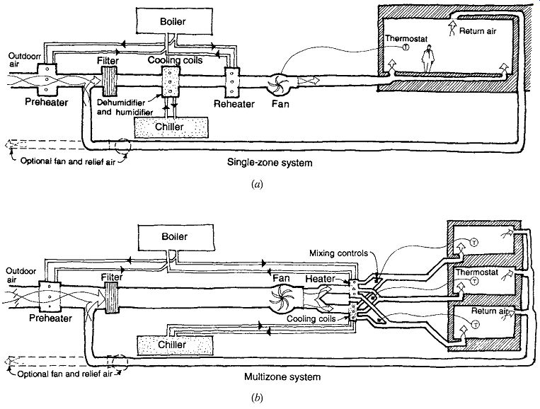
Fig. 12 (a-f) Schematic diagrams of all-air HVAC systems. An underfloor
air supply is shown here to simplify the diagram, but a ceiling supply is much
more common.
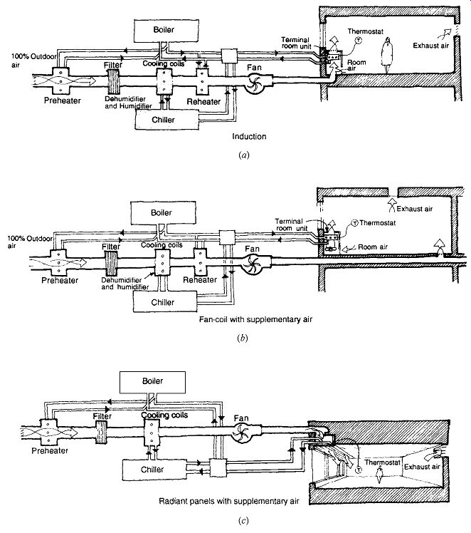
Fig. 13 (a-c) Schematic diagrams of air and water HVAC systems. An underfloor
air supply is shown here to simplify the diagram, but a ceiling supply is more
common. In (b) the supplementary air is often delivered directly to the fan-coil
unit.
Dual-Duct, Constant-Volume Systems. The dual- (or double-) duct system requires two complete distribution trees (Fig. 12d); at the height of summer the cooling airstream does all the work, whereas in the coldest winter conditions the heating airstream carries the load. Most of the time, air from these two streams is mixed to order at each zone's air terminals. Because both temperature and volume can be controlled, this system offers better comfort under reduced load conditions (for example, an only partially occupied room) than does the single-duct VAV system. However, it is much more expensive to install, consumes much building volume for the two distribution trees, and usually consumes more energy than the single-duct VAV system that has largely replaced it.
(c) Air and Water Systems
Several variations on air and water systems are shown in Fig. 13. Most of the heating and cooling of each zone is accomplished via the water distribution tree, which is much thinner than the tree needed by air. For air quality-filtering, humidity, freshness-a small, centrally conditioned airstream, equal to the total fresh air required, is pro vided. Thus, several distribution trees are involved, yet the total space they require is almost always less than that required by all-air systems.
Exhaust air may be gathered in a return air duct system, making heat recovery possible. Or (as a cheaper alternative) air can be exhausted locally to avoid the construction of yet another distribution tree. If the water distribution provides either heating or cooling only, it is called a two-pipe system (shown throughout Fig. 13). If it provides simultaneous heating and cooling, it is a four-pipe system.
(Three-pipe systems are a lower-first-cost alternative allowing simultaneous heating and cooling [from two supply pipes with a single return pipe], but they waste energy by mixing hot return and cold return water flows in one return pipe. They are no longer permitted in most locales.) This class of system frequently serves the perimeter zones of large buildings, whereas all-air systems (commonly, single-duct VAV) are used for the interior zones. More details on this HVAC class can be found in Section 10.6.
Induction Systems. This (Fig. 13a) previously common system's terminal units may be found below windows throughout the United States. A high-velocity (and high-pressure), constant-volume fresh air supply is brought to each terminal, where it is forced through an opening in such a way that air already within the room (bypass, or secondary, air) is induced to join the incoming jet of air. A fairly thorough circulation of room air is thus accomplished with only a little centrally treated air. Air then passes over finned tubes for heating or cooling. Thermostats control the unit's output by controlling either the flow of the water or the flow of secondary air.
Fan-Coil with Supplementary Air. Another (Fig. 13b) familiar piece of below-window equipment is the fan-coil, which moves room air as it provides either heating or cooling. Centrally conditioned, tempered fresh air is brought to the space in a constant-volume stream; the fan moves both fresh and room air across a coil that either heats or cools the air, as required.
Radiant Panels with Supplementary Air. As suggested in Fig. 13c, either ceiling or wall panels contain the heated or cooled water to provide a large surface for radiant heat exchange. Centrally conditioned, tempered fresh air is brought to the space in a constant-volume stream. The "piece of equipment" within the space is replaced by a large surface, which must be kept clear of obstructions to radiant heat exchange.
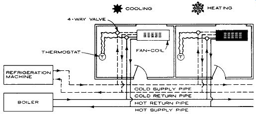
Fig. 14 Schematic diagram of all-water HVAC systems. Four-pipe distribution
trees require smaller volumes than do those for air systems; however, less
thorough provision of outdoor air is a potential concern.
Water Loop Heat Pumps. Because individual heat pumps are used, this system is closely related to direct refrigerant systems. It is often considered an all-water system, but may be configured with a central outdoor air supply (as in an air-water sys tem). Heat pumps (water-to-air) either draw heat from the water circulation loop (in heating mode) or discharge heat to it (in cooling mode). For a large building in cold weather, excess heat from the interior zones is used to warm the perimeter zones. The loop's temperature ranges between 65ºF and 90ºF (18ºC and 32ºC); in hot weather, a central cooling tower disposes of the loop's excess heat, whereas in cold weather a central boiler adds needed heat to the water loop. The loop is sized to carry 2 to 3 gpm (0.13 to 0.19 L/s) per ton, where the total tonnage equals the sum of the capacity of all the individual units (often greater than the actual load).
(d) All-Water Systems
The more simple-appearing all-water systems are shown in Fig. 14. These systems only heat and cool; the distribution trees are indeed slim. Air quality is dealt with elsewhere-either locally, by means of infiltration or windows; or by a separate fresh air supply system; or simply by fresh air from an adjacent system, such as a ventilated interior zone. This ambiguity about fresh air leads to similar ambiguities about whether a system is air-and-water or all-water. A fan-coil terminal is often employed so that air motion occurs along with heating or cooling. (Sometimes the fan-coil unit is located against the exterior wall so that fresh air may be brought in and mixed with the room air through the fan.) Both baseboard and valence (above-window) units are also commonly available.
Because air is handled so locally, there is very little mixing of air from one zone to another, making this attractive where potential air contamination (or smoke from a fire) is a special concern. It is also an easy system to retrofit. However, maintenance is high; filters in each fan-coil must be cleaned, and drain pans are potentially problematic.
More details on this HVAC system class can be found in Section 10.7.
Two-pipe water distribution systems were shown throughout Fig. 13. They provide either heating or cooling. One pipe is for supply, the other for return. In a typical large-building application, they are used for heating in winter, cooling in sum mer. This raises the question of what changeover period will be required, a problem made much easier with the following alternative system.
Four-pipe systems are shown in Fig. 14.
They allow quick changeover between heating and cooling, utilizing two supply and two return pipes. A four-pipe system also allows for simultaneous cooling and heating in different zones within a single distribution system.
(e) Equipment Space Allocations
An important early design decision is whether to integrate or separate the heating/cooling equipment and the air-handling equipment (see Fig. 2). If they are integrated, one or a few central mechanical room(s) can serve many floors, and each mechanical room will need area and height sufficient for both heating/cooling and air-handling equipment.
If separated, one (or several, in tall buildings) large space for heating/cooling equipment is typically located in the basement or the penthouse, with a smaller fan room on each floor.
Each mechanical room should have both a central location relative to the area it serves and direct access to the outside-contradictory requirements in many cases. Central locations within the area served minimize the distribution tree size; access to the outdoors facilitates the use of outdoor air as a heat source (winter) or sink (summer) and allows equipment to be installed or removed in later remodeling. Mechanical rooms serving both heating/cooling and air-handling equipment need relatively high ceilings; 12-ft (3.7-m) clear is a typical minimum, 20-ft (6-m) clear a typical maximum.
Tables 3 and 4 present the approximate space requirements for conventional mechanical systems. (For a more detailed look at equipment room space requirements, see Figs. 18, 29, and 42.)

Table 3 Approximate Space Sizes for Major Heating and Cooling Equipment

Table 4 Approximate Space Sizes for Air-Handling Equipment
The sizing graphs shown in Tables 10.3 and 10.4 are generous if buildings are designed with energy conservation in mind. For buildings with large heat gains or losses, these graphs may slightly undersize the areas needed. These graphs are intended to give a very fast approximation of areas; more detailed procedures for sizing are presented in Section 10.3 (for boilers, chillers, fan rooms) and Section 10.4 (for air ducts).
Cooling equipment capacity is often rated in tons of refrigeration. The relationship between tons and floor area served is explored in Table 5.
For the thermally well-designed detached residence of today, a design guideline is 1000 ft^2 of floor area/ton (26 m^2/kW).

Table 5 Tons of Refrigeration: Design Guidelines
Fig. 15 Some basic components of HVAC central equipment. (a) A simplified diagram of a cooling cycle, in which chilled water is circulated to air-handling coils and heat is disposed of through a cooling tower. (b) Schematic diagram of major components of central equipment for both heating and cooling.
3. CENTRAL EQUIPMENT
The many HVAC systems that are included in the categories of all-air, air and water, and all-water have in common a dependence on central equipment for the generation of heating and cooling, and/or air quality control. Figure 10.15 shows the basic relationships between some of the major pieces of central equipment and the spaces they serve. This section offers a general guide to some central equipment options and sizes. The consulting engineer chooses such equipment based upon a much more detailed analysis.
(a) Boilers
These devices heat the recirculating hot water sys tem used for building heating. The type of boiler selected depends on the size of the heating load, the heating fuels available, the desired efficiency of operation, and whether single or modular boilers are to be installed. Boiler sizes are commonly stated either in Btu/h of net output or in (gross) boiler horsepower, where, in I-P units, boiler horsepower heating load(Btu / h)
%bo = iiler efficiency
× 33,470 Btu/h per horsepower
In SI units, boiler horsepower heating load(kW)
%boile = r r efficiency × 9.81 kW per horsepower
Efficiency depends partly on the number of passes that the hot gases make through the water- the more passes, the higher the efficiency. It also depends on burner efficiency and on regular maintenance. Finally, efficiency is best when the equipment is operating near its capacity. Figure 10.16 compares typical boiler types, including two- and three-pass boilers.
Fire Tube Boilers. The hot gases of the fire are taken through tubes that are surrounded by the water to be heated. Firebox boilers place the boiler shell on top of the combustion chamber. Scotch marine boilers feature multiple passes of the combustion gas through tubes. Fire tube boilers can be either dryback or wetback. Dryback designs have chambers outside the vessel to take combustion gases from the furnace to the tank. Wetback designs have water-cooled chambers that conduct the combustion gases.
Water Tube Boilers. The water to be heated is taken through tubes that are surrounded by the boiler's fire. They hold less water than the fire tube models, and so respond faster and can generate steam (where desired) at higher pressures.
Cast-Iron Boilers. Often used in residential and light-commercial applications, these are lower pressure and lower-efficiency boilers. They do have the advantage of being modular.
In addition to the boilers themselves, there are choices of burner types (depending on the fuel[s] used), burner controls, and boiler feedwater systems. Consult the latest ASHRAE Handbook-HVAC Systems and Equipment for details.
Fossil fuel-burning boilers need flues for exhaust gases, fresh air for combustion, and required air pollution control equipment. The exhaust gas is usually first taken horizontally from the boiler; this horizontal enclosure, or flue, is called the breeching.
The vertical flue section is called the stack. Guide lines for sizes and arrangements of breeching and stacks are shown in Fig. 17. Local codes deter mine the quantity of air required for combustion; local air pollution authorities set pollution control requirements. As a general rule, combustion air can be supplied in a duct to the boiler at an average velocity of 1000 fpm (5.1 m/s). The duct should be large enough to carry at least 2 cfm (1 L/s) per boiler horsepower. Furthermore, ventilation air to the boiler room should be provided; preferably, the inlet and outlet should be on opposite sides of the room.
Minimum sizes: enough for 2 cfm (1 L/s) per boiler horsepower at a velocity of about 500 fpm (2.5 m/s).
Space requirements for boilers are summarized in Fig. 18, which shows multiple boilers. Note that clear space within the room must be provided so that the tubes of the boiler can be pulled when they must be replaced. Access for eventually replacing entire boilers must be considered.
Several types of single boilers are discussed here. The final boiler type discussed, the modular boiler, is preferred for energy conservation.
1. High-output, package-type steel boiler. For large buildings that use steam as a primary heating medium, one or several such boilers may be used. Direct use of steam can be seen in Fig. 15b, supplying preheat and reheat coils and also a humidifying unit. The relative lightness of this boiler type, compared to the older styles with ponderous masonry bases (boiler settings), makes it suitable for use on upper floors of tall buildings. Figure 10.6 shows two such boilers on the 13th floor of the Fox Plaza Building.
2. Converter, steam to hot water. When, in a building that uses primary steam boilers, secondary circuits that use hot water for heating are required, a converter (Fig. 19) is used. It is considered a heat exchanger. In Fig. 6, there is downfeed steam supply for the two boilers on the 13th floor to two such converters, one for hot water heating in the apartments and one below the garage ceiling for hot water heating in the commercial area. A converter may also be used to transfer heat from steam to domestic (service) water. Converters are frequently used where central steam supply systems are available, as in large-city downtown areas. The easier, quieter distribution of heat by hot water has largely replaced steam heating distribution trees within buildings.
3. Electric boilers. Where electricity costs are competitive with those of fossil fuels, electric boilers are sometimes used. Both hot water and steam electric boilers are available. The advantage of electric boilers is the elimination of combustion air, the flue, and air pollution at the building.
The disadvantages are the use of a high-grade energy source for a relatively low-grade task and the pollution impact at the electric generating plant. In order to protect against high electric demand charges, a large number of control steps are desirable.
4. Compact boilers. Smaller-dimension boilers (Fig. 20) with high thermal efficiencies are available. In addition to their space-saving footprint, they feature a variety of venting options that make them easily adaptable to smaller equipment rooms.
5. Modular boilers. The primary advantage of modular boilers (Fig. 21) is efficiency.
Boilers achieve maximum efficiency when they are operated continuously at their full rated fuel input. The single boilers discussed previously operate this way only under outside design conditions, which by definition occur, at most, during 5% of a normal winter. In a modular boiler design, each section is run independently. Therefore, only one section need be fired for the mildest heating needs; as the weather gets colder, more sections are gradually added.
Because each section operates continuously at full-rated fuel input, efficiency is greatly increased (Fig. 22). Each module, being rather small, requires little time to reach a useful temperature and (unlike the larger single boilers) does not waste a lot of heat as it cools down. Thus, modular boilers usually produce a 15% to 20% fuel savings for the heating season relative to single boilers. Their other advantages include ease of maintenance (one module can be cleaned while others carry the heating load) and small size (allowing easy installation and replacement in existing buildings).
Modular boilers also eliminate the initial cost of oversizing heating equipment. In cold climates, conventional boiler systems often use two or three large boilers to ensure that heat is available even if one large boiler fails. When two such boilers are used, it is common practice to size each boiler at two-thirds of the total heating load; an oversize of one-third results. When three such boilers are used, it is common practice to size each boiler at 40% of the total heating load; an oversize of 20% results. However, when a minimum of five modular boilers are used, oversizing can be eliminated because the failure of a single module will not have a crippling impact on the overall heat output.
Gas-fired pulse boilers are an even smaller and more energy-efficient choice for modular boilers.
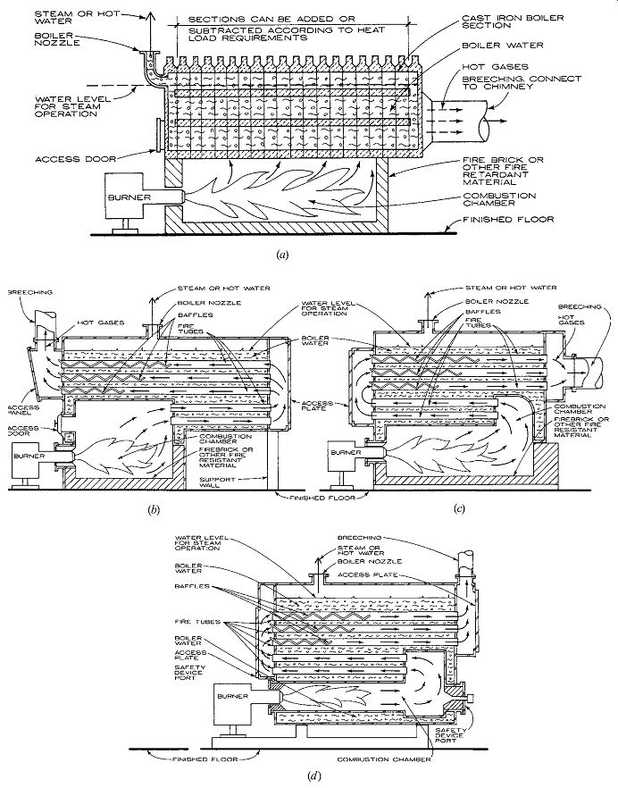
Fig. 16 Comparisons of boiler types. (a) Cast-iron sectional type. (b)
Two-pass fire tube. (c) Three-pass fire tube. (d) Three-pass wetback Scotch
marine.
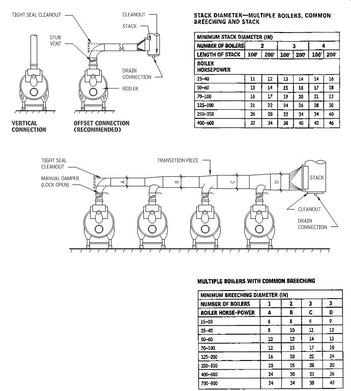
Fig. 17 Breeching and stack size guidelines for fossil-fuel-fired boilers.
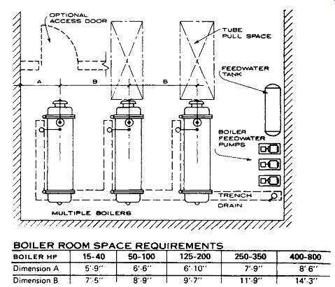
Fig. 18 Boiler room space requirements. Dimension A includes an aisle of
3 ft 6 in. (1 m) between the boiler and the wall. Dimension B between the boilers
includes an aisle of at least 3 ft 6 in. (1 m), and up to 5 ft (1.5 m) for
the largest boilers.
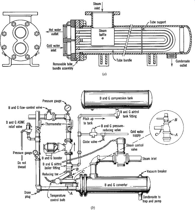
Fig. 19 Conversion unit that transfers heat from steam to hot water. (a)
Section illustrating the principle of heat transfer from steam to water. (b)
A converter connected to the steam supply and equipped with all devices necessary
for a complete hot water heating system.
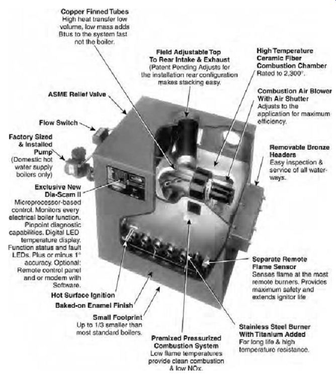
Fig. 20 Burkay Genesis hot water boiler, fueled by either natural gas or
propane, is available in ratings from 200,000 to 750,000 Btu/h (58,620 to 219,825
W). All units are 30 in. high × 24 in. deep (762 mm × 610 mm); the smallest
boiler is 23 in. (584 mm) wide, and the largest is 57 in. (1454 mm) wide. The
copper heat exchanger has an 83.7% thermal efficiency rating, and a variety
of venting options are available.
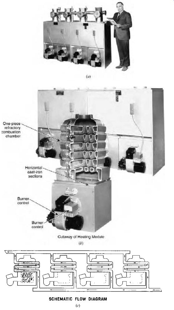
Fig. 21 Modular boilers. (a) A bank of four modules-with a total input
1.5 million Btu/h (439 kW). (b) Details of one module (20 x 32 x 48 in. H [510
x 812 x 1220 mm]) with a 385,000 Btu/h (113 kW) input. (c) Schematic of flow
conditions in mild weather, with only one module in operation.
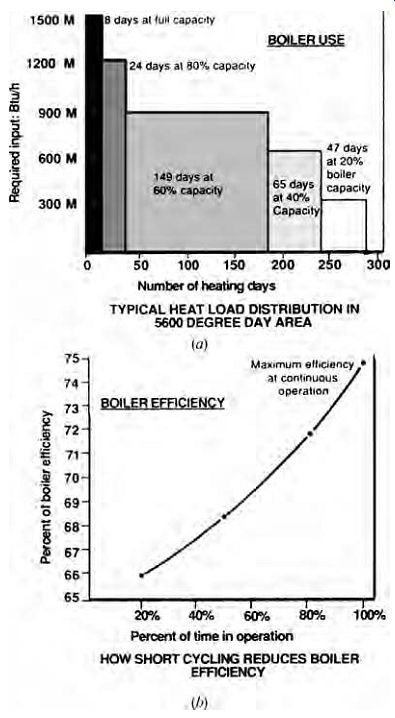
Fig. 22 One large boiler versus many smaller ones. (a) Boilers rarely operate
at full capacity; instead, they respond to part loads the majority of the time.
(b) Under part load conditions, a boiler will often short-cycle, which on a
single large boiler could drop the annual efficiency into the 66% to 75% range.
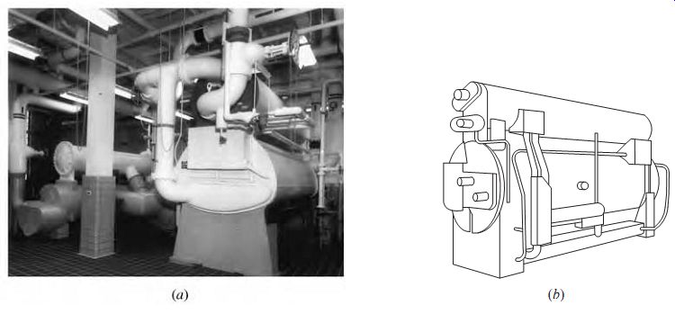
Fig. 23 (a) An absorption chiller driven by heat to produce chilled water.
(b) Two-stage absorption chiller utilizing steam, producing 200 to 800 tons
(700-2800 kW) of cooling.
Pulse boilers utilize a series of 60 to 70 small explosions per second, making the hot flue gases pulse as they pass through the fire-tube. This makes for very efficient heat transfer. Pulse boilers are available up to about 300,000 Btu/h (88 kW).
Pulse boilers operate with lower water temperatures so that water vapor in the flue gas can condense and drain. This change of state liberates additional heat, allowing these pulse boilers to achieve efficiencies up to 90%. They exhaust moist air, not hot smoke, so flues can be small-diameter plastic pipe rather than large-diameter, heat-resistant materials.
(b) Chillers
These devices remove the heat gathered by the recirculating chilled water system as it cools the building. The selection of chillers depends largely on the fuel source and the total cooling load. Chillers include both absorption and compressive refrigeration processes in a wide range of sizes.
New developments in chillers continue to result from a combination of concerns about the role of CFCs and HCFCs in global climate change and from changes in utility regulations that are producing unstable energy prices in many areas.
Chillers capable of changing quickly between electricity and natural gas are becoming available as a result.
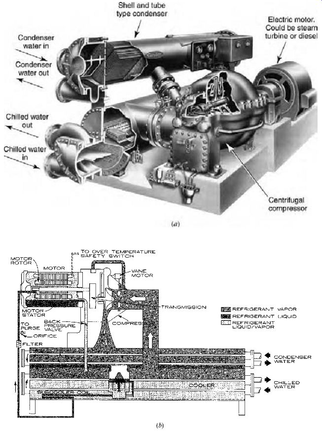
Fig. 24 (a) A centrifugal chiller-a machine of large capacity using the
compressive refrigeration cycle. (b) Centrifugal chiller with a flooded cooler
and condenser within a single outer shell. This low-pressure unit typically
produces 100 to 400 tons (350-1400 kW) of cooling. Typical dimensions are:
14 ft L x 5 ft W x 8 ft H (4.3 x 1.5 x 2.4 mm), at 16,000 lb (7260 kg).
The single-effect, indirect-fired absorption chiller (Fig. 23) is attractive where central steam or high-temperature water (from solar collectors, as waste heat from an industrial process, a fuel cell, etc.) is available. This device uses the absorptive refrigeration cycle. Direct-fired absorption chillers use natural gas to power the cycle. In general, absorption equipment is less efficient than compressive refrigeration cycle equipment, although a cheap or even free heat source to power the cycle can rapidly overcome efficiency disadvantages. Absorption machines have fewer moving parts (and therefore require less maintenance) and are generally quieter than compressive cycle equipment. They are environmentally attractive, despite their much higher waste heat output (about 31,000 Btu/ton, compared to at most 15,000 Btu/ ton for compressive cycle equipment), because they do not use CFCs or HCFCs and because they require far less electricity to operate. Newer developments include the double-effect absorption chiller (see Fig. 3) and the triple-effect chiller, each accompanied by an increase in efficiency.
The compressive refrigeration cycle (explained in Fig. 9.1) is used in the other types of chillers.
Larger units are centrifugal chillers (Fig. 24), whose compressors either can be driven by an electric motor or can utilize a turbine driven by steam or gas. (When a steam-driven turbine is used, the exhaust steam is often used to run an auxiliary absorption cycle machine. These two devices make an efficient combination, and the steam plant that supplies them in summer can supply heating in winter.) Centrifugal chillers usually require about 1 hp/ton (0.57 kW, or 10 ft 3 gas, or about 15 lb of steam per ton). These large chillers usually require a cooling tower. Dual-condenser chillers (Fig. 25) can choose whether to reject their heat to a cooling tower (via the heat rejection condenser) or to building heating (via the heat recovery condenser).
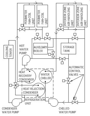
Fig. 25 Dual-condenser chiller. Heat drawn from the chilled water system
is either rejected to the cooling tower or recovered for use in building heating.
Somewhat smaller chillers use either twin screws or a scroll in place of a piston in the compressor. The screw compressor (Fig. 26) has a pair of helical screws; as they rotate, they mesh and thus compress the volume of the gas refrigerant.
They are small and quiet, with little vibration. The scroll compressor (Fig. 27) uses two inter-fitting spiral-shaped scrolls. Again, the refrigerant gas is compressed as one scroll rotates against the other fixed one. Gas is brought in at one end while the compressed gas is released at the other. Quiet and low-maintenance, they are also more efficient than reciprocating compressors.
Even-smaller compressive-cycle machines are called reciprocating chillers (Fig. 28). Usually electrically driven, they are often combined with an air-cooled heat rejection process rather than a cooling tower. This makes them a closer relative of the smaller direct refrigerant machines discussed in Section 9.8.
Chilled water is usually supplied at between 40ºF and 48ºF (4ºC and 9ºC). When the chilled water is supplied cold and returns much warmer, the large rise in temperature reduces the initial size (cost) of equipment and increases its efficiency (thereby reducing the operating cost as well). Water treatment may be needed for chilled water to control corrosion or scaling.
Typical cooling capacities and space requirements of chillers are shown in Fig. 29-with dimensions as tabulated. Each refrigeration machine in this illustration requires two pumps- one for the chilled water (to cool the building) and one for condenser water (to deal with reject heat). Typically, space is provided for future chiller additions, which may be required by building expansion and/or by higher internal gains from as-yet-uninstalled equipment, such as computer terminals within offices. Improved-efficiency chillers may replace older ones when energy costs and environmental regulations become compelling.
Adequate clearance access to the equipment room is a major design issue.
Fig. 26 A screw, or helical, compressor is a quieter, smaller machine with
little vibration.
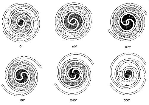
Fig. 27 Scroll compressor rotates one scroll form against another, with
a quiet and efficient compression of the refrigerant.
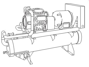
Fig. 28 A reciprocating
chiller-a small-capacity machine that uses the compressive refrigeration cycle.
Typically, this type of chiller produces less than 200 tons (700 kW) of cooling.
Such a machine might be around 8 ft L x 3 ft W x 5 ft H (2.4 x 0.9 x 1.5 m)
and weigh 3500 lb (1590 kg).
(c) Condensing Water Equipment
With chillers, there must be a way to reject the heat that is removed from the recirculating chilled water system. Reject heat is handled by the condensing water system, which serves the condensing process within refrigeration cycles. For larger buildings, the condensing water requirement is most likely to be met by a cooling tower.
The cooling tower's place within the over all equipment layout was shown in Fig. 15b; a more detailed guide to sizes and types is given in Figs. 10.30 and 10.31. The object is to maximize the surface area contact between outdoor air and the heat condensing water. In crossflow towers, fans move air horizontally through water droplets and wet layers of fill (or packing), whereas in counterflow towers (prevalent in larger buildings), fans move the air up as the water moves down.
Cooling towers create a special-and usually unpleasant-microclimate. They demand huge quantities of outdoor air (approximately 300 cfm [142 L/s] per ton), which they make considerably more humid. In cold weather, they can produce fog. They are typically very noisy-a natural consequence of forced-air motion. The condensing water flows are about 2.8 gpm (0.18 L/s) per ton of compressive refrigeration and about 3.5 gpm (0.22 L/s) per ton of absorption refrigeration.
The water that escapes as vapor from the tower is between 1.6 and 2 gph (1.7 and 2.1 mL/s). This water must be replaced, which is done automatically. The steady evaporation and exposure to the outdoors under hot and humid conditions spells trouble for the condensing water: Controls for scaling, corrosion, and bacterial and algae growth are especially important. Ozone treatment systems have the advantage of reliable biological control and leave no chemical residue. Since the discovery of the link between Legionnaire's disease and cooling towers, biological control has assumed greater importance.
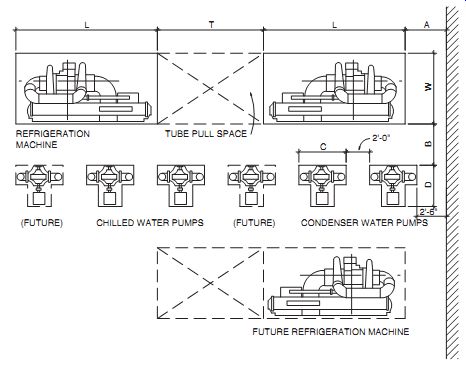
Fig. 29 Chiller room space requirements. Each refrigeration machine is
served by two pumps (chilled water and condenser water).
The vapor that escapes the cooling tower should be kept from the vicinity of fresh air intakes, and from neighboring buildings or parked cars, where feasible. The floor space requirements can be approximated from Table 3, or use the average of 1/500 of the building gross floor area (for towers up to 8 ft [2.4 m] high) or 1/400 of the building gross floor area (for higher towers).
Although it is tempting to try to block the noise of cooling towers with solid barriers, it is critical that noise control not interfere with air circulation.
The manufacturer's recommended clearances to solid objects near cooling towers must be consulted an always-closed loop, while a separate body of water is recirculated through the cooler, with steady evaporation and attendant problems. It requires much less makeup water than the cooling towers.
(d) Energy Conservation Equipment
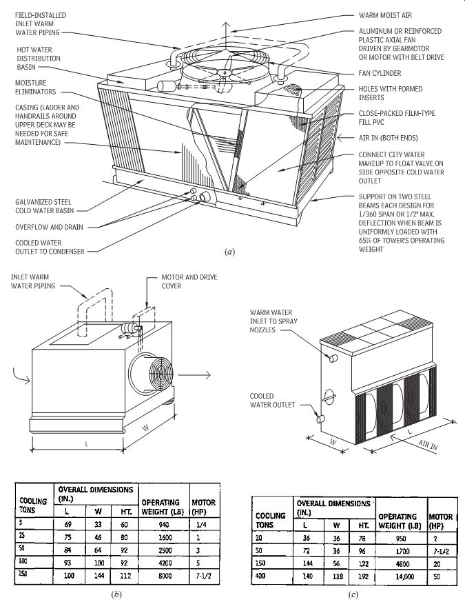
Fig. 30 Cooling towers that serve the condensing water system for large
buildings. (a) Cutaway view of a large-capacity (200 to 700 tons [700-2460
kW]) crossflow induced-draft package cooling tower. (b) Size ranges for crossflow
induced-draft package cooling towers. (c) Size ranges for counterflow induced-draft
package cooling towers.
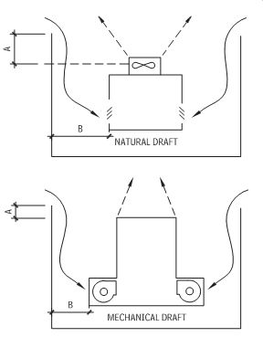
Fig. 31 For cooling towers, the more wall clearance, the better the operation.
A = maximum height of enclosure above the tower outlet; minimize this dimension.
B = as large as possible, especially if walls have no air openings.
One big advantage of central equipment rooms is the opportunity they present for energy conservation. Regular maintenance is simplified when all the equipment lives in a generous space kept at optimum conditions; with regular maintenance comes increased efficiency of operation. Another conservation opportunity is that of heat transfer between various machines, or between distribution trees, where one's waste meets another's need.
Boiler flue economizers achieve heat transfer by passing the hot gases in a boiler's stack through a heat exchanger, thus preheating the incoming boiler water (Fig. 34).
Runaround coils (Fig. 35) can be used for heat transfer between intake and exhaust air ducts when these two airstreams are rather far apart. This circulating heat-transfer fluid usually contains anti freeze; it provides simple sensible heat transfer, with no restrictions on exhaust and intake location. No contamination of intake air by exhaust air is caused by this arrangement. The efficiency of such coils runs between 50% and 70%, and they are available in modular sizes up to 20,000 cfm (9440 L/s).
Heat exchange between incoming and exhaust airstreams, which was discussed in Sections 5.6(c) and 5.6(d), allows heat pipes and thermal transfer wheels to play major roles in energy conservation.
The thermal transfer wheels can add to the central equipment space requirements. Other desiccant systems were discussed in Section 5.6(d).
Economizer cycles (Fig. 36) use cool outdoor air, as available, to ease the burden on a refrigeration cycle as it cools the recirculated indoor air. The economizer cycle can thus be thought of as a central mechanical substitute for the open window; when it is cool enough (below the supply air temperature), 100% outside air can be provided and no chilled water is needed. When the outdoor air temperature is higher than the supply air temperature but lower than the return air temperature, 100% outdoor air is still brought in, but chilled water is used to lower its temperature. Above the return air temperature, outdoor air is reduced to that volume required for IAQ.
Relative to open windows, this cycle has several advantages: energy-optimizing automatic thermal control, filtering of the fresh air, tempering of the cool outdoor air to avoid unpleasant drafts, and an orderly diffusion of fresh air throughout the building. Its disadvantages are the loss of personal control that windows offer and thus loss of awareness of exterior-interior interaction. In hot, humid climates, the moisture brought by 100% outdoor air may be unwelcome.
Economizer cycles are available as options on most direct refrigerant machines (such as single package rooftop units) and are typically installed for large-building central air supply systems.
Buildings with high internal gains (internal load dominated) are particularly good targets for economizer cycles because they need cooling even when the outside temperature is chilly. Economizer cycles lend themselves readily to a cooling strategy of night ventilation of thermally massive structures because they have a built-in option for 100% outdoor air.
(e) Geo-exchange Systems
Using the earth as a heat source and sink for small buildings was explored in Section 9.8(d). Four typical applications were shown in Fig. 9.44. Larger buildings can also utilize such systems. A late 1990s building just east of Central Park, in New York City, utilizes two wells 1500 ft (457 m) deep; all but the top 50 ft (15 m) are lined by bedrock. Heat is taken from (or discharged to) water, which is pumped from one well and discharged to the other-a "groundwater source" system. The average year-round temperature in these deep wells (in an intensely urban area) is estimated at 56ºF (13ºC), about the temperature at which chilled air is delivered to a space in summer.
Going to such depths is perhaps the only geothermal option in densely built-up areas.
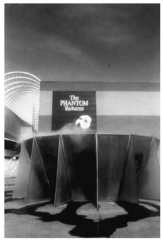
Fig. 32 A plume of mist hovers ghostlike above a cooling tower in full
public view near the Denver performing arts complex.
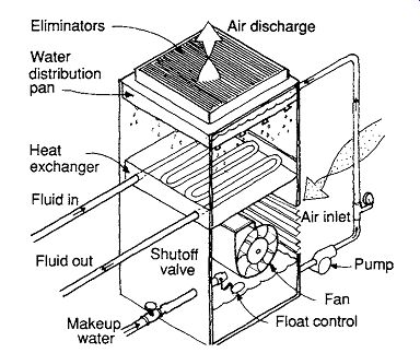
Fig. 33 Closed-circuit evaporative coolers, which cool the condensing water
system while protecting it from contact with outside air. A self-contained
water system is circulated through the evaporative cooler; steady evaporation
losses are replaced by makeup water.
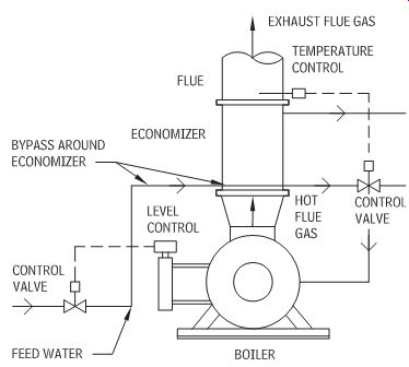
Fig. 34 Heat recovery for boilers. Flue gas entering at 500ºF (260ºC) leaves the "economizer" at 325ºF (163ºC), a temperature still high enough to prevent condensation in the stack. The heat recovered here is added to incoming
boiler water, raising its temperature from 200 to 248ºF (93 to 120ºC).
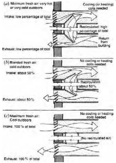
Fig. 36 The economizer cycle controls the relationships among fresh, exhaust, and recirculated air. (a) When outside air is hot (or very cold), the economizer
cycle is inactive, and minimum fresh air is introduced. (b) As very cold outside
air gets warmer, it can be blended with recirculated air, and neither heating
nor cooling coils are needed. (c) When outside air is cool, it can completely
replace circulated air, making mechanical cooling inactive.
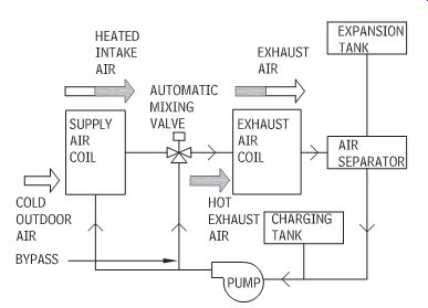
Fig. 35 Runaround coils for heat transfer between fresh intake air and
stale exhaust air, used where the air streams are in separate locations. Efficiencies
can range from 50% to 70% and coil capacities up to 20,000 cfm (9400 L/s).
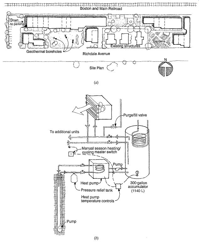
Fig. 37 Cambridge (Massachusetts)
Cohousing development takes advantage of three boreholes on its urban site
(a) to provide central heating and cooling, serving individual residential
fan-coil units. It also preheats water (b) for the DHW (domestic hot water)
system. The residences are sited to provide winter solar access, and a positive
fresh air intake is located on the side sheltered from adjacent railroad tracks.
Underground parking preserves open space for gardens and recreation.
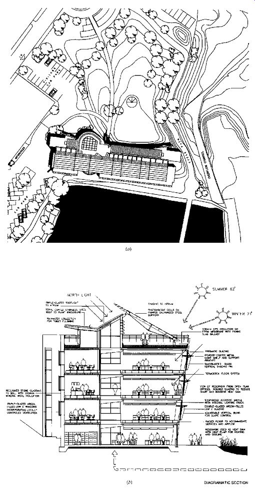
Fig. 38 The Hyndburn Borough Council ( England) headquarters faces south
toward a reservoir (a) that provides an evaporatively cooled microclimate and
also acts as a heat source/sink for a water-water heat pump. (b) As suggested
in the diagrammatic section, daylighting, passive solar heating, PVs, and a
well-insulated shell are featured. Termodeck is a precast hollow-core slab
that stores coolth on summer nights and pre-cools ventilation air. The supply
air then rises from the plenum created by the raised floor.
The Cambridge ( Massachusetts) Cohousing Project (Fig. 37) is also located in a densely settled urban neighborhood. The 41 living units feature passive solar heating, underground parking (this reserves some 20,000 ft 2 [1860 m2] of the surface for open green space), and centralized heating/cooing utilizing ground source heat pumps with locally controlled thermal zones. In this urban setting, the relative quiet of the indoor heat pump's compressors and the lack of noisy hot air (summer) or cold air (winter) discharges are welcome amenities.
In England, the Hyndburn Borough Council decided that their new headquarters building should set an example as a "zero energy" building: that is, over a typical year, it should generate as much energy as it imports. The 38,750-ft 2 (3600-m2) building (Fig. 38) is elongated east-west and boasts an ambitious section that combines daylighting, photovoltaics (PV), a well insulated skin, and even rainwater collection to use for flushing toilets. Windpower adds to electricity generation. Summer cooling is by ventilation (assisted by night ventilation of mass) through a raised "Termodeck" system. This is a prefabricated hollow-core slab through which cool night air circulates, storing coolth to assist the next day's hottest hours. (This is a concept explored by the Oregon office building in Fig. 8.6.) The raised floor then provides a distribution plenum, with a design rate of 4 air changes per hour (ACH).
For more extreme future summer cooling, but now mostly for winter heating (beyond that pro vided by passive solar heating), an adjacent reservoir acts as a thermal sink. A "lake closed source heat pump" will serve the mechanical ventilation system. The lake is south of the building, providing some local evaporative cooling in summer and inviting a very climate-oriented south façade, behind which are open-office areas. The north façade faces the city and is more traditionally institutional in character, as are the individual offices behind it.
(f) Energy Storage
We commonly experience daily changes from warmer to colder conditions, both in winter and in a hot, dry summer. Central storage equipment for large buildings can take advantage of this cycle to increase operating efficiency, save energy, and significantly reduce electricity demand charges. Some electric utilities offer incentives to install thermal storage in order to reduce the peak strain on their generating facilities.
Water storage tanks are one common approach to storage, such as those shown in Fig. 39. On typical winter days, the total internal heat generated by a large building can be somewhat greater than its total need for heating at the perimeter zones. Instead of being thrown away as exhaust air, this surplus heat is captured and stored in large water tanks, from which it can be withdrawn and used on cold winter nights and weekends. In the summer, chillers can work at night, when efficiency is high because cool outdoor air helps the refrigeration cycle reject its heat. By storing the coolth produced, less work need be done by chillers during the next day's peak, when electric rates are highest and operating efficiency is lowest.
Design guidelines for water storage are 0.5 to 1 gal/ft^2 (20 to 40 L/m^2) of conditioned space. Such large, heavy tanks are frequently located in basements and underground parking facilities. Water tanks require additional floor space for equipment, although they may allow somewhat smaller chillers to be installed. They may also contribute to lower fire insurance premiums because consider able water is stored and ready to use.
Ice storage tanks are another storage approach, as shown in Fig. 40. Because they take advantage of the latent heat of fusion (143.5 Btu/lb of water at 32ºF [334 kJ/kg at 0ºC)]), such units can store far more energy in a given-size tank than can water. Design guidelines for ice storage are 0.13 to 0.25 gal/ft^2 (5 to 10 L/m^2) of conditioned space.
A comparison of the relative sizes of storage tanks needed for an 18-story office building is shown in Table 6. Also, with ice storage there is less undesired mixing of hot and cold water within the tank.
Ice can be made in several ways. A common method is to form ice as a layer around a pipe that carries refrigerant in a closed circuit through the tank. Control of the thickness of this layer is important, because if too little ice is made at night, too little cooling will be available the following day. In another method, ice is formed and thawed by circulating a brine through coils in cylindrical water tanks. Other methods form ice on plates, then harvest it in an insulated bin.
The Iowa Public Service Building (Fig. 41) uses ice storage in six tanks that occupy about half of the floor space in the ground floor mechanical room. This installation serves a five-story, 167,000-ft^2 (15,515-m^2) utility office building that utilizes solar collectors supplemented by small backup boilers. The six ice-making machines serve a 75,000-gal (283,900-L) ice storage pit with 90 million Btu (26,355 kWh) capacity. Winter heat exchange opportunities include reject heat from the ice-making machines, heat from the central toilet exhaust air, and heat from return air taken through luminaires. Solar collectors on the roof preheat the ventilation air, which is fed into the ceiling plenum at each floor. Fan-coil units then draw from this fresh air supply.
Water and ice storage tanks are sometimes located at the top of a building, especially when other related mechanical equipment is there also.
Despite the weight of such tanks, they can become a structural advantage. The tuned mass damper method of reducing lateral vibration (or sway) in high-rise buildings utilizes a heavy, moving mass at the top; when the building begins to sway, the mass is moved in the opposite direction. In the Crystal Tower in Osaka, Japan, this mass is provided by ice storage tanks. This 515-ft (157-m), 37-story building has an ice thermal storage total of 25,400 ft 3 (720 m^3) divided into nine tanks. Six of the ice storage tanks provide the movable structural mass, suspended from roof girders, weighing 540 tons (489,880 kg), including steel framing. The chiller and condenser are also in the equipment penthouse.
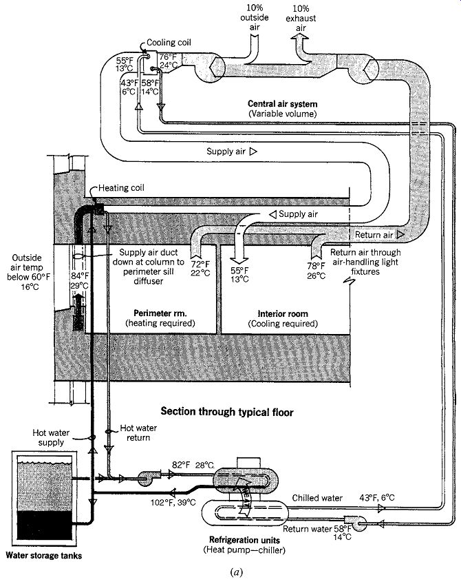
Fig. 39 Water tank heat storage. The 870,000-ft^2 (80,825-m^2) transportation
office building ( Park Plaza, Boston), population 2000, uses a three-compartment
insulated concrete tank storing 750,000 gal (2,838,990 L) of water. (a) At
an outside air temperature of 40º to 50ºF (4.4 to 10ºC), the surplus internal
heat is stored in the tanks rather than rejected as exhaust air. (b) By the
time the outside air is about 50ºF (10ºC), the tanks are fully charged; up
to an outside temperature of 60ºF (15.5ºC), the economizer cycle provides energy-conserving
cooling. (c) At about 60ºF (15.5ºC) chillers must operate, but working all
night when the outside air is cooler enables them to work less by day. Their
nightly production is stored as cold water, available to help with the following
day's peak.
Smaller machines and more efficient operation are the result.
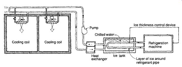
Fig. 40 Ice tank heat storage. Chilled water in an ice tank forms a layer
of ice around the refrigerant pipe (supplied by the refrigeration machine).
As chilled water at about 35ºF (1.7ºC) is removed from the tank, it enters
a heat exchanger, so that its temperature is closer to 45ºF (7.2ºC) for distribution
to cooling coils throughout the building.
(g) Air-Handling Equipment
A given HVAC system type may have many variations. In some variations, all the air is passed through one central equipment room. In others, air handling may be done in many separate and smaller rooms, whereas central heating and cooling require only one equipment room. Some detailed design guidelines for air-handling equipment for either case are shown in Fig. 42. Air-handling equipment room dimensions are shown in Table 7. Total air quantities (cfm) may be estimated from Table 4 or obtained more precisely from cooling load calculations.
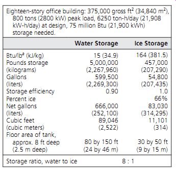
Table 6 Cooling Storage Comparison
Some common fan types include:
Panel: The most simple type on this list; for high efficiency air delivery, the motor is generally mounted in the center of the propellers. It is likely the noisiest type. It is not designed for much static pressure from ductwork, filters, and so on.
Fixed pitch vane axial: Capable of working against somewhat more static pressure than the panel fan; more common in industrial applications.
Centrifugal: With an airfoil bladed wheel, it has high efficiency over a wide operating range and is quieter than the previous two. Major changes in pressure result in only minor changes in the volume of air delivered.
Vane axial adjustable pitch: Takes less space than centrifugal fans and can work against more static pressure. The pitch is adjustable occasion ally, not continuously, for system balancing or seasonal changes in air volume.
Vane axial controllable pitch: The automatically con trolled pitch responds to changes in tempera ture, humidity, airflow, and so on, depending on the sensors used. It is commonly used in VAV systems.
Filters and other methods of IAQ control were discussed in Section 5. There are numerous combinations of air handlers, filters, and coils for air heating/cooling, selected by the consulting engineer. For the architect, the primary issues include adequate space, adequate access (for current maintenance and future equipment replacement), and noise isolation.
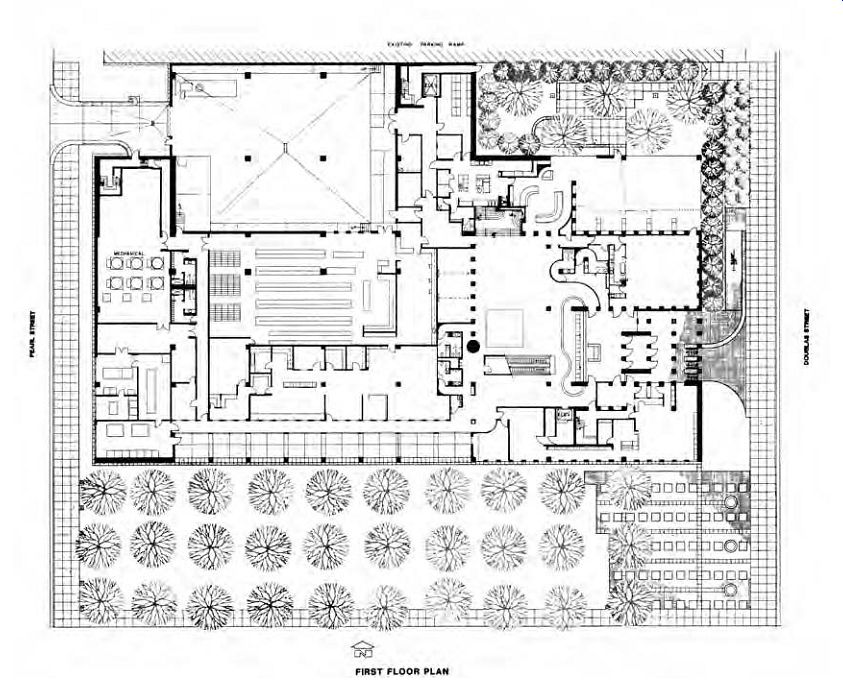
Fig. 41 The ground floor of the Iowa Public Service offices ( Sioux City)
contains six ice machines within the mechanical space adjacent to the loading
dock.
(h) Controls
Although the most obvious HVAC control function is to maintain desired comfort conditions, controls also increase fuel economy by promoting optimum operation and act as safety devices, limiting or over riding mechanical equipment. They also eliminate human error: controls fall asleep only during a power failure.
Although precise control of temperature and humidity everywhere in a building may be a tempting thought, controls can usually maintain only a range of conditions, not a precise setpoint. This range (within which neither heating nor cooling is called for) is called the deadband. Temperature variations occur vertically within a space-the higher the space, the greater the variation. Variations between horizontal positions within a zone are highly likely, especially where one or more walls are exterior and where different rooms share a zone controlled by a single thermostat. Variations in time also occur: a building will always be warmer at the moment the heating system turns off than at the moment the system turns on.
Individual controls can be classified as follows: controllers, which measure, analyze, and initiate action; actuators, which are the controller's servants and in turn become the masters of pieces of equipment; limit and safety controls, which may function only infrequently, preventing damage to equipment or buildings; and accessories, a miscellaneous collection.
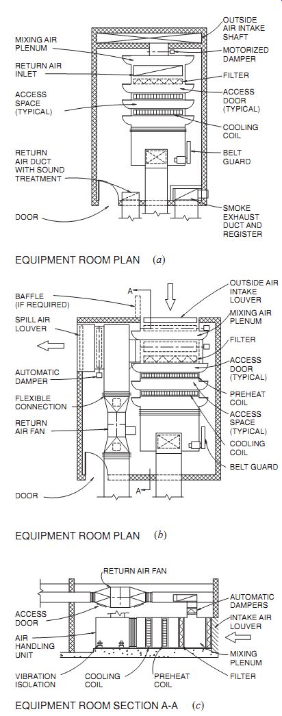
Fig. 42 Some variations on a huge variety of HVAC equipment rooms. (a)
Plan with floor-mounted air-conditioning unit.
Outdoor air is drawn from an adjacent shaft; return air ducts are above the equipment, and a remote exhaust fan expels what is not recirculated. (b) Plan on an exterior wall. Outdoor air is taken through the wall, and a return air fan is overhead. (c) Section through plan b
Systems of controls can be classified by power source: electric (both analog and direct digital control); pneumatic (in which compressed air is the motivating force); and self-contained, including "passive" controls such as those motivated by thermal expansion of liquids or metals. Another way to classify control systems is by the motion of the controller equipment: two-position systems are of the simple on-off type; multiposition systems have several varieties of the on position, commonly used for separate operation of more than one machine; floating controls can assume any position in the range between minimum and maximum; central logic control systems can be programmed to integrate the many aspects of building control into one decision making unit, and are now the prevalent approach to building management.
Control diagrams for two common HVAC applications are shown in Fig. 43. Single-duct VAV systems (Fig. 43a) are further described in Section 10.5; with the constantly varying flow rate, the fan must be regulated so as to maintain the minimum pressure (and therefore, flow) needed at the most demanding outlet. This outlet may be either the one most remote from the fan or the one needing the greatest flow (because it serves the highest load) at the moment. Economizer cycles (Fig. 43b) compare outside to inside positions, and vary the proportion of fresh (outdoor) air to return air, to provide "free" cooling (see again Fig. 36).
Most of today's large buildings are regulated by central logic control systems, usually called building management systems (BMS). The goal is a productive, cost-effective environment achieved by optimizing the interrelationships among the building's structure, systems, services, and management. The HVAC system is centrally regulated and interconnected with lighting, electric power (such as load shedding), elevators, service hot water, access control and security, telecommunications, and information management. Such systems not only maintain comfort with energy conservation, they also sound the alarm about malfunctions, can learn from past practice, and keep records of performance.
This integration and automation of the many building control systems is made possible through direct digital control (DDC), which can be applied to a wide variety of elements. They provide "dynamic control" in the case of HVAC, anticipating time based changes in heat flow patterns or in occupancy schedules. These actions depend on direct digital microcontrollers located on each piece of regulated equipment throughout the building. Three building types show applications of this comprehensive automated control opportunity.

Table 7 Air-Handling Equipment Rooms
Laboratories have proven to be especially difficult HVAC control problems due to their fume hoods. Conditioned air is provided from the central HVAC system, often by a VAV supply. Whenever a fume hood is exhausting air (frequently in huge quantities), the VAV supply and return systems are affected. Complicating this relationship is the nature of the laboratory work; where the experiment could be damaged by outside contaminants, the lab should be positively pressurized to minimize infiltration (and the VAV must therefore supply and return slightly more air than the fume hood exhausts). However, where the experiments involve diseased, toxic, or other hazardous substances, the lab must be negatively pressurized (and the VAV must supply and return slightly less air than the fume hood exhausts). DDCs tied to a central system can balance energy conservation, lab worker safety, and safety for the non-lab environment.
Hotel rooms can present serious energy loss problems from heating/cooling either an unoccupied room or a room with open windows. With DDCs inter-tied with the registration desk, an "unoccupied" mode of operating can be remotely controlled, with bare-minimum heating or cooling. When the room is occupied, the supply of either hot water heating or cooled air can be throttled back whenever the window is open.
Also, a "purge" mode can enable a new arrival (or the front desk, in anticipation) to select a greatly increased flow of outdoor air for a limited time period to dilute cigarette smoke or other odors.
Section 30 presents more detailed information on intelligent buildings.
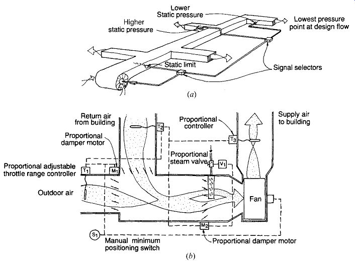
Fig. 43 Controls for some common HVAC applications. (a) Single-air VAV.
(b) Economizer cycle.
Offices might be provided not only with DDC for the VAV supply units, but also with inter-tied DDCs for an interconnected ventilating window (preventing simultaneous open windows and treated forced air delivery), daylight reflectors (mini-light shelves), venetian blinds, a radiant heater valve, an electric light switch, and an insulating shade. A control panel or "dashboard" gives the worker an opportunity to interact with the central control in operating these devices.
Office buildings that use more passive strategies also benefit from BMS. The British Research Establishment building for fire research, "Building 16" (Fig. 44), depends upon cross- and stack ventilation for its cooling, and upon movable louvers on the south windows for sunshading and daylight penetration. A common network links this building's control systems; each worker has a TV-like controller that regulates lights and can override the programmed settings of the nearest high-level windows (for ventilation) and south window louvers (for sun control and daylighting). This innovative office building uses a ground source heat pump (borehole type) to supplement solar and internal winter heat gains or to provide supplementary cooling to the night ventilation system. Note the provisions for cross-ventilation for individually enclosed offices on the ground floor, utilizing a cavity above the ceiling to carry the ventilation air on to exhaust on the other side of the building.
Rapid changes in centralized control systems are continuing. Initially, DDC systems were developed by individual companies, with little or no opportunity for communication between systems.
Such proprietary systems left designers frustrated by an inability to specify a wide variety of products, all controlled by a single BMS. In the late 1990s, two competing systems had emerged that promised integration of products and systems from different manufacturers. BACnet was developed by ASHRAE committee members as a nonproprietary communication standard. LonMark was developed by the LonMark Interoperability Association, a user funded organization of building owners, specifiers, system integrators, and product suppliers. Open control system architecture is an opportunity for a BMS in which components from several vendors interoperate over a BACnet-adapted Ethernet LAN (local area network). It makes possible a system combining BACnet, LonMark, and proprietary subsystems (Fig. 45).
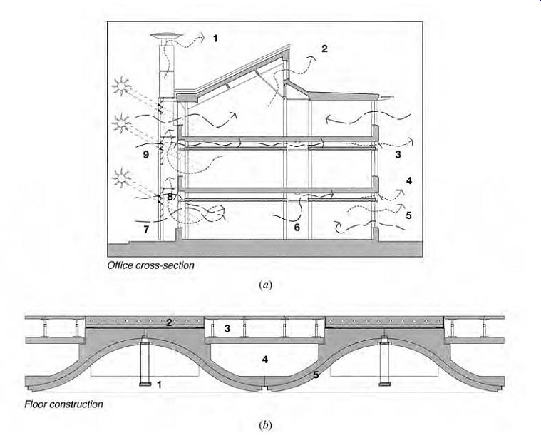
Fig. 44 Natural ventilation and daylight strategies dominate the north-south
section (a) of the British Research Establishment Building 16 at Garston. (1)
Stack ventilation (hot, calm); (2) clerestory BMS-controlled ventilation; (3)
night ventilation through slab, BMS controlled; (4) cross-ventilation bypass
over enclosed offices; (5) enclosed office single-sided ventilation; (6) corridor
cross-over zone; (7) manually operated lower-level windows; (8) high-level
BMS-controlled windows; (9) motorized external shading louvers, also BMS controlled.
(b) East-west section detail of precast floor structure. (1) Luminaire with
integral photosensors; (2) heated/cooled screed using a geothermal source;
(3) raised access floor for wiring; (4) cross-ventilation duct (night ventilation
and/or cross-over ventilation for enclosed offices); (5) waveform precast concrete
ceiling with poured-in-place topping slab.
4. AIR DISTRIBUTION WITHIN SPACES
When large office buildings had far greater interior (core) areas than perimeter areas and were filled with less-efficient lighting at high luminance levels, they were considered to always need cooling. Because cool air supplied at the ceiling would naturally fall toward the level of occupants, and because suspended ceilings were ubiquitous, sup ply air from the ceiling was almost universal. The suspended ceiling was also tempting for the return air provisions, whether as a plenum or for another ducted system. With both supply and return air at the ceiling, the danger of short-circuiting arose: supply air heading quickly for the return opening, with resulting shortages of both cooling and IAQ. In this section, we first look at approximate duct sizing and then consider three air distribution systems for multistory office buildings.
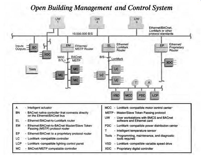
Fig. 45 Building Management System (BMS) that is open to various protocol
standards.
(a) Air Ducts
Duct sizes (in cross section) are frequently of interest early in the design process. Duct depths can help determine floor heights; duct cross sections influence the sizes and shapes of the vertical cores that serve multistory buildings. An approximation of duct size can be obtained as follows:
1. Determine the quantity of air to be distributed through the largest duct, using Table 5, or the ACH developed (for example) from a calculation of night ventilation of thermal mass (usually expressed in cubic feet per hour, cfh).
2. If necessary, convert cfh to cfm:
cfh 1 h 60 min cfm × =
3. Find the maximum velocity of this air within the duct from Table 9.4, expressed in feet per minute (fpm).
4. The approximate minimum required cross-sectional area of duct A is then Ain.
2 volume of air (cfm) velocity (fpm)
=× 144 in. 2/ft^2 × friction allowance where the friction allowances are
• round ducts = 1.0 (may be neglected)
• nearly square ducts (ratio of width to depth, 1:1) small (<1000 cfm) = 1.10 large (>1000 cfm) = 1.05
• thin rectangular ducts (ratio of width to depth, 1:5) = 1.25
Then check this against the recommended duct cross-sectional area from Table 4.
Remember that the minimum duct area will carry a penalty of increased noise and friction.
Techniques for noise suppression in ductwork are discussed in Section 19.
(b) Ceiling Air Supply
This approach is so widespread that many lighting fixtures are made to either serve as diffusers for supply air or as intakes for return-air. As return-air fixtures, they are especially effective because they remove much of the heat from electric lighting before it can contribute to overheating the office space below. This makes less work for the space cooling equipment.
When individual offices are enclosed, a sup ply diffuser and return grille ensure air circulation. However, as open office space proliferated, concerns grew about whether the workspace cubicles were being adequately served with conditioned air.
Air diffusers and grilles (Fig. 46) on the ceilings are uncluttered by furniture and independent of rearrangements of workstation cubicles. Canadian research in the early 1990s indicated that the most important variable was the quantity of the airflow, not the location of the diffusers relative to workstations or whether the cubicle partitions have a small gap where they meet the floor.
Are higher ceilings better for air distribution? There seems to be a trade-off between more vertical clear space (between ceiling and cubicle partitions) that would allow a wider range of air distribution and the increased distance from the actual occupant who should be receiving the conditioned air. The increased distance would allow colder air to be distributed, resulting in smaller ducts, and could also allow higher velocity of supply air, further reducing duct size. Higher ceilings allow deeper daylight penetration and represent a larger "pool" of air that is slower to become polluted by occupants or office equipment. Higher ceilings also encourage under floor distribution, as seen in the next subsection.
When the noise from forced-air diffusers is critical, as in telecasting and recording studios, pinhole perforated diffusers (Fig. 47) can provide large quantities of low-velocity air. These occupancies represent an especially challenging combination of high heat gains (from lights) and low background noise requirements. Again, ceiling distribution leaves the floor unencumbered.
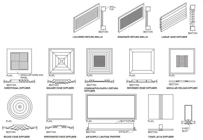
Fig. 46 Common air distribution outlets.
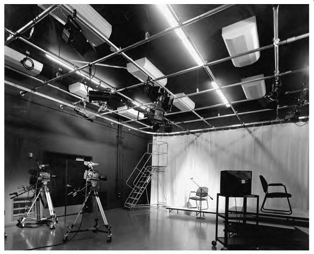
Fig. 47 Pinhole-perforated diffusers (above a lighting grid) provide large
quantities of low-velocity air to the television studio at the Community Media
Center of Santa Rosa, California. The background noise from more typical HVAC
systems would be amplified by sound recording equipment and hence would be
unacceptable.
(c) Underfloor Air Supply
As open office spaces have grown larger in area and their ceilings higher (for daylight penetration and indirect lighting), and as concerns about IAQ have deepened, the floor has gained in popularity as the air source location. Underfloor air supply introduces supply air, through floor outlets, cooled to just below the design room temperature, at a low velocity. (Displacement ventilation supplies air at very low velocity, such that there is little to no turbulence in the space.) Furthermore, fresh air supply rates are typically near 45 cfm (22 L/s), compared to about 30 cfm (15 L/s) often used in ceiling supply systems. This high-volume, low-delta_t, low-velocity combination requires greatly increased duct sizes, essentially provided by using the plenum formed by a raised floor system as a duct. The supply air rises quickly to the occupant level, drawn upward by the stack effect of heat gain from lights, people, and office equipment (and by supply air pressure). It continues to the ceiling, where it stratifies and where various approaches to return-air collection can be located. Freshest and coolest at the floor, hot test and most stale at the ceiling, this system promises better IAQ and thermal comfort than would be available from ceiling supply-return systems. Furthermore, the outlets at the floor are adjustable and easily reached by the office workers.
The raised floor is typically supported on a 2 × 2-ft (600 × 600-mm) module. The module that contains the diffusing outlet often also contains an outlet for power and cable. This diffuser is placed off center within the modular unit, further expanding the variability of the floor opening relative to furniture placement, because each plan rotation of the square module places the outlet slightly differently.
Some codes restrict the height of the raised floor plenum; many codes require specially coated wiring within the plenum because moving air will wash over the wires for the life of the building.
The overall floor-to-floor height needs to be great enough to accommodate both the raised floor and the higher office ceiling (at least 9 ft [2.7 m] to accommodate warm air stratification). However, elimination of the suspended ceiling and the supply air ductwork also eliminates the suspended ceiling cavity. This tends to expose the lighting, fire sprinkler, and public address systems below the structural ceiling, although the latter can be distributed in the raised floor cavity above and puncture the structural ceiling as required.
The structural slab below the raised floor can be of concrete, and this thermal mass can be night ventilated to store coolth to assist the ventilation air for the next day. The Inland Revenue Building (discussed in Section 8) incorporates a night ventilated raised-floor section within its precast waveform floor sections.
Library Square in Vancouver, British Columbia (Fig. 48), utilizes a raised floor to serve its interior zones of book stacks. The library has seven floors, totals 390,000 ft 2 (36,320 m2), and exposes its concrete structure as a finished ceiling. The floor-to-floor height is 16.4 ft (5 m). The under floor supply is fed by VAV boxes and floor fan units (FFU) that blend low-temperature supply air (about one-third) with local filtered return air (about two thirds) to provide 63ºF (17ºC) air to the pressurized plenum. Flush to the floor, high-induction swirl floor diffusers (8 in. [200 mm] in diameter) produce an upward air motion, taking the fresh return-air blend directly into the occupancy zone (the first 6.5 ft [2 m] of height on each floor). The stack effect of heat from people, computers, and lights takes hot air on to the stratification zone above. Thus, people generated pollutants tend to rise to this hot, stale air zone, then into return-air slots in the precast concrete ceiling. Return air is taken away in insulated ducts within the supply air plenum of the floor above. The plenum height is an unusually generous 2 ft (600 mm) high; it also contains the sprinkler distribution and all wiring systems. The warm, dry summer climate supports a night ventilation system, flushing the plenum and storing coolth in the exposed concrete structure. This has reduced the use of an ice-storage system.
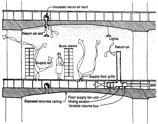
Fig. 48 Library Square, Vancouver, British Columbia, supplies conditioned
air to the central book stacks via an underfloor plenum.
This displacement ventilation results in return air taken through openings in the exposed structural ceiling.
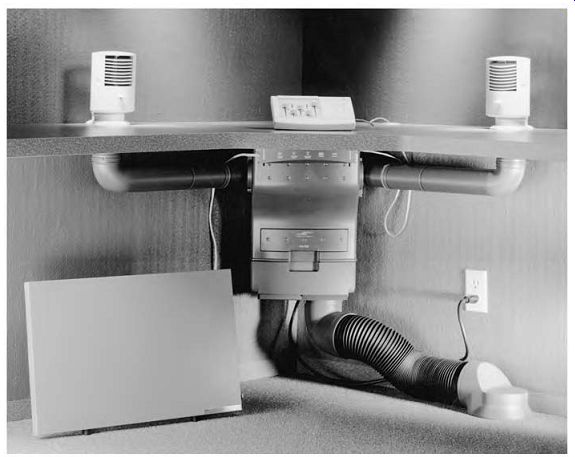
Fig. 49 The Personal Environments system provides each workstation with
a fan, air filters, an air-mixing box, and a background sound (white noise)
generator. The control panel allows adjustment of task lighting, background
sound, fan speed, primary/recirculated air mixture, and radiant heating. Two
diffusers distribute both air and background sound. Diffusers are adjustable
about both horizontal and vertical axes. The below-desk radiant heating panel
warms the lower body.
(d) Workstation Delivery Systems
The air delivery system shown in Fig. 49 allows a variety of individual controls at each workstation.
As developed by Johnson Controls, Inc., these systems are called Personal Environments systems.
A mixture of outdoor and recirculated indoor air, called primary air, is brought from the main duct (or floor plenum) to each Personal Environments system's mixing box in a duct carrying at most 120 cfm (56 L/s) but typically less. Each worker can adjust the supply air temperature, the mixture of primary and locally recirculated air, air velocity (and therefore volume) and direction, and radiant supplementary heat (below desk level). Task lights can be dimmed, and the background (masking) sound level is adjustable. The worker has almost as much environmental control at each office work station as a driver has in an automobile's front seat. When the workstation is unoccupied, an occupancy sensor shuts the system down, maintaining a minimum airflow of 12 cfm (5.7 L/s).
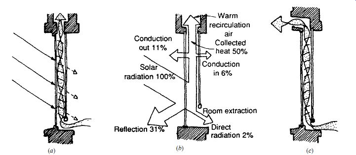
Fig. 50 Air extract window
(also called an air curtain or climate window). (a) Cross section showing the
window as a solar collector. (b) Distribution of solar heat in the collector
mode. (c) The window as a "solar chimney" exhausting hot air. (d)
The U-factor of these windows varies with the rate of airflow within the glazing:
the typical flow rate is 4 to 6 cfm per foot (6 to 9 L/s per meter) of window
width.
(e) Alternative Supply/Return Systems
So far, the supply/return systems discussed have been either both from the ceiling or supply from the floor and return at the ceiling. Supply from the ceiling, return through the floor is another possibility.
The fresh air gets to the occupancy level later, and individual control is much more difficult, but debris from the floor falls into a return, not a supply, plenum. There seems less danger of debris falling into a floor supply diffuser while the system operates; it is during fan-off periods, which may include custodial maintenance, that this possibility increases.
An alternative approach with return at the perimeter is shown in Fig. 50. It is variously called an air-extract window, an air curtain window, or a climate window. Developed in Scandinavia in the 1950s, this is a triple-glazed window that passes room air between a typical outer double-glazed window and an inner single pane. The inner pane thus is kept at very nearly the same temperature as the room air, which greatly increases comfort near windows on very cold (or very hot) days. Venetian blinds are often inserted in this cavity, where they can intercept direct sun and redirect its light toward the ceiling. The solar heat intercepted by the blind is carried off by the room air to a plenum above the ceiling, where such air can be either exhausted or recirculated and its heat content either reclaimed or rejected. The U-factor of these windows is dependent upon the rate of airflow within the glazing panes (Fig. 50c); typical flow rates are 4 to 6 cfm per foot (6 to 9 L/s per meter) of window width.
The Ocosta Junior/Senior High School at West port, Washington (Fig. 51), uses these windows on the south façade. (For an example of such windows in a larger U.S. building, see Fig. 63, which shows the Comstock Center in Pittsburgh.) The classrooms have photocells that switch off some lights nearest the windows when daylight is adequate, and water loop heat pumps help to transfer passive solar heat from the south side to the sunless north side rooms. Excess heat in the Ocosta school is stored in an underground water tank. The compact plan, highly insulated envelope, and mass capacity within the school reduce the need for a boiler to supplement the winter temperature of the water loop. During consistently warm weather, the BMS exhausts the air from the window to the outdoors.
Supply openings in vertical risers are relatively rare but at times function effectively. The Frederick Meijer Gardens (Fig. 52) near Grand Rapids, Michigan, is a huge indoor tropical rain forest. This glass structure is more than 65 ft (20 m) high; it has more glass area than floor area-great for a high daylight factor, but imagine the heating loads! High humidity must be maintained, yet water condensation on leaves is undesirable. A strong horizontal airflow could be helpful to the plants, acting as wind would to develop a stronger root structure.
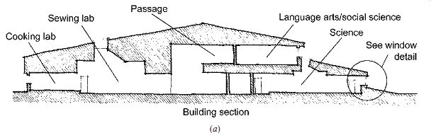
Fig. 51 The Ocosta Junior/Senior
High School at Westport, Washington, uses air extract (air curtain) windows
to help distribute solar energy from the south side (to the right in section
a) to the north classrooms. (b) Detail through the south-facing windows. Photocells
control the electric lighting during daylight hours; venetian blinds direct
sunlight toward the ceiling and deeper into the classroom.
The solutions here begin with a perimeter tunnel serving as an air supply duct, delivering air evenly around the glass walls, heated by finned tubes at planting level that are largely hidden by foliage. The tunnel insulates the planting beds from the extremes of the exterior, maintaining constant ground temperatures year-round. A separate "wind" system continuously feeds air to vertical ducts with several diffusers (Fig. 52b), making leaves and branches sway. Humidity is provided by a high-pressure water system that creates fog (very small water particles). This is located high in the space (but also near waterfalls and a stream for special effects). This is also an evaporative cooling system to counteract summer overheating. Peak airflow is needed only for cooling; return air is taken through a large opening hidden behind a waterfall.
About one-third of the peak supply air is returned; the remainder is exhausted at the top of the structure through operable vents high in the glass roof.
A BMS controls the roof vents, the fogging system, the finned-tube heating system, rolling shading screens, and the heating/cooling equipment in a basement, all in response to changing conditions outside this enormous glass house.
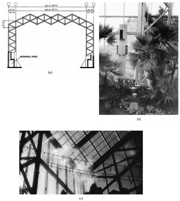
Fig. 52 With more glass area than floor area, the Frederick Meijer Conservatory
near Grand Rapids maintains a tropical environment in Michigan's winter. (a)
A perimeter tunnel delivers air evenly around the walls, heated by finned tubes
just above the planting level. (b) A separate "wind" system provides
a continuous breeze from diffusers in the vertical ducts to strengthen plants'
root systems. (c) A fogging system maintains tropical humidity while adding
evaporative cooling under summer conditions.
5. ALL-AIR HVAC SYSTEMS
This large, complex family of systems was introduced in Section 10.2. All-air HVAC systems require thick distribution trees-therefore more building volume-but can promise comfortable results because they can effectively regulate IAQ, tempera ture, and humidity. This approach concentrates the mechanical equipment and its maintenance within a central mechanical room, freeing the rest of the building from repair interruptions and worries about water leaks from heating/cooling pipes. However, this family does less well with perimeter zones in cold climates.
With all-air systems, air quality can be manipulated through pressure control: negative pressures in odorous or excessively humid locations (kitchens, toilet rooms, pet shops in shopping centers, etc.), positive pressures in shopping malls, corridors of apartment houses, stair towers, and so on. The difference in pressure sets up an overall direction of airflow that helps prevent the spread of odorous or otherwise contaminated air and can help manage smoke in a fire (see Section 24). Positive pressures in connecting spaces help each adjacent space keep its air to itself.
(a) Single-Zone Systems
Smaller buildings are often served by this (Fig. 12a) least-complicated all-air example. Where an entire building is essentially one thermal zone, uncomplicated enough to be served by only one thermostat, this system offers a very low first cost.
A closely related system is the multizone (see later in this Section), which is a combination of single zones.
(b) Single-Duct VAV Systems
As described in Section 10.2, this system (Fig. 12c) is an energy-saving option ideally suited to the internal zones of large buildings, where cooling is always needed. However, it can also be adapted to serve the entire building, with important savings over the constant-volume (CV) systems described later. The air-handling units (fans, etc.) for each thermal zone are sized to meet the peak demand on that zone. In most CV systems, the fans always run at this peak-condition speed, even though peaks are often of rather short duration. In VAV systems, fans run at peak speed only during peak hours. This saves considerable energy other wise used to run fans at constant speed. When the building uses only one or a few central fans, a VAV system will require smaller fans because the fans need to meet only one peak condition at a time and do not have to be sized for all zones' peak flows. The variation in demands on the fan can be met either by selecting variable-pitch blades or (less expensively) by varying the speed of the fan.
Where a VAV system is used, provision must be made for at least code-minimum fresh air levels, sometimes resulting in overcooling or wasteful reheating. Although VAV systems are typically less noisy than CV systems (because less air is moving), the air motion noise varies with the volume, and variable noise sources are inherently more notice able than steady ones.
Within (or near) the spaces it serves, the VAV system typically needs a mixing box or terminal; this is often placed above a suspended ceiling or below a raised floor. Of the several terminal types available, the standard and most simple one is shown in Fig. 53. This terminal serves not only to vary the quantity of air, but also to both attenuate the noise and reduce the velocity of air from the main trunk of the distribution tree. High velocity is commonly used in main ducts because it reduces the size (thickness) of these critical large portions of the tree.
The Utah Department of Natural Resources in Salt Lake City (Fig. 54) utilizes VAV through out its three-story, 105,000-ft^2 (9755-m^2) office building. Air is supplied from linear ceiling diffusers located between the rows of indirect luminaires parallel to the windows. Return air is taken into the suspended ceiling plenum. Highly insulated walls, windows, and roof lessen the need for perimeter heating, although a supplementary warm water heating system is built in below the windows to off set perimeter heat losses. The lower 1 ft (300 mm) is a slot where room air is drawn in by convection, and a perforated metal grille at the top forms the windowsill.
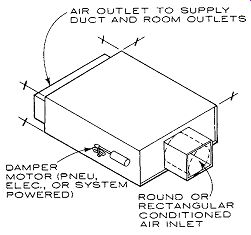
Fig. 53 The most simple type of VAV terminal, which pinches back the volume
of incoming air as cooling loads decrease.
Boxes can range in size: 8-18 in. H by 24-67 in. L by 14-54 in W (200-460 x 610-1700 x 360-1370 mm).
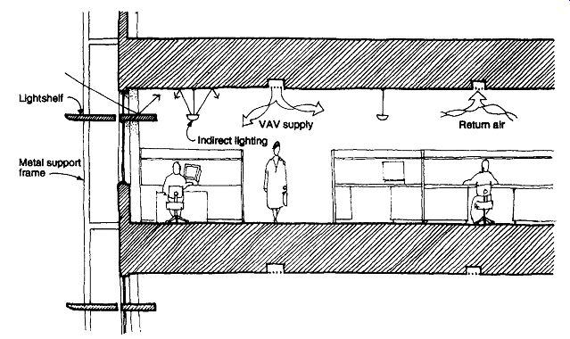
Fig. 54 The Utah Department of Natural Resources building features lightshelves,
direct and indirect evaporative cooling, and an economizer cycle. Supply air
is distributed by a VAV system with ceiling diffusers located between luminaires.
The building is elongated east-west for best daylight control and winter solar gain; lightshelves even the daylight penetration. With almost no east- or west-facing glass, the building relies on 4200 ft^2 (390 m^2) of south glass and 3800 ft^2 (353 m^2) of north glass to serve its width of 125 ft (38 m). Supplementary indirect lighting is controlled by photo cells and dimming ballasts.
Utah's hot, dry summers permit a four-stage approach to cooling. First is the economizer cycle (see Fig. 36); at higher temperatures, direct evaporative cooling is used; then indirect evaporative cooling utilizing an oversized cooling tower; and finally (estimated at about 10 days per year), a conventional chiller.
There are several variations on the basic VAV system, some of which respond to the problem of minimum airflows for rooms with little thermal load or to the desire to serve both interior and perimeter areas with the same HVAC system.
(c) Fan-Powered VAV Systems
To maintain minimum fresh air, VAV terminals are usually set so that they cannot be entirely closed off, ensuring some outdoor air at all times. If this fresh air minimum, entering at low velocity, does not provide the desired air motion and mixing within the room, VAV terminals can be equipped with fans (Fig. 12f), which are activated as needed with decreasing incoming air volume. These self contained fans mix room air with incoming air to provide an airstream of the right temperature and velocity to maintain comfort.
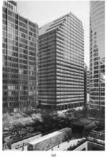
Fig. 55 Floor-by-floor fan rooms supply VAV for this Chicago office building.
(a) Exterior view of 33 West Monroe. ( Merrick, Hedrick-Blessing.) (b) Plan
of a typical lower floor; two fan rooms occupy the space along the exterior
wall. (c) Section perspective showing stacked atriums.
This approach to VAV is sometimes taken when simultaneous heating and cooling are needed, such as at perimeter zones, which can generate sizable heating needs while the rest of the building needs cooling. Another approach is to utilize an induction-type VAV terminal, with which air heated by electric lights is induced to join the incoming cool airstream. Greater heating needs often require the use of reheat terminals supplied by a circulating hot water system or by electric resistance heating. This reheat application is more energy efficient than the standard CV reheat sys tem described in Section 10.5(e), because a much smaller volume of air is first cooled, then reheated.
The water or electric coils can be incorporated either in the VAV terminal or in the ductwork between the terminal and the space it serves.
An example of a floor-by-floor VAV system (Fig. 55) is a 1-million-ft^2 (92,900-m^2) 28 floor Chicago office building designed by Skidmore Owings & Merrill. This mid-rise approach to office towers utilizes three "stacked" atriums to relieve the monotony of the wide interior floors. Another result is lower structural and energy costs per square foot relative to conventional high-rise structures. The cube-like shape of the building exposes less skin area (38% of which is in insulating glass) to Chicago's cold winters; electric lighting at about 1.8 W/ft^2 (19.4 W/m^2) holds down internal gains. To accommodate the differing schedules and comfort needs of a variety of tenants, each floor is provided with two VAV supply fans that can be operated at night and on weekends, independently of the rest of the building. Each floor's mechanical core has one exterior wall (on an alley) to facilitate fresh air intake/stale air exhaust. The perimeter heating system is electric resistance fin radiation; an economizer cycle provides cooling with out door air below 55ºF (13ºC).
(d) Multizone Systems
A multizone system (Fig. 12b) is a collection of single-zone systems served by a single sup ply fan; such systems rarely exceed eight zones per air-handling unit. Simultaneous heating of some zones and cooling of others is possible, but leakage between zones at the decks of hot and cold coils is common. Return air from all zones is mixed within one return duct; a bypass at the heating and cooling decks requires more space but allows such air to be mixed with supply with out undergoing unnecessary heating or cooling.
One multizone system per floor of medium- to high-rise buildings is an increasingly common application.
(e) Single Duct with Reheat
Once a widely used system and usually supplied at constant volume (CV), single-duct reheat systems (Fig. 12e) now are severely restricted by many building codes and energy standards. For high-pressure and high-velocity main ducts, CV reheat boxes (Fig. 56a) are used to control the temperature, pressure, and velocity of the supply air, and to mitigate noise. For more simple all-low velocity systems, simple duct insert heaters (Fig. 56b) can be used. These are sized to fit the duct, which needs to be enlarged only slightly to accommodate them.
(f) Dual-Duct Systems
This (Fig. 12d) is still considered the "Cadillac" of HVAC systems, not only because of its superior comfort control and flexibility for simultaneous heating/cooling zones, but also because of its high first cost, large size, and high energy usage. The dual-duct system is rarely installed now, except in hospitals. Building volumes needed for a dual-duct system's three (two supply, one return) full-sized air distribution trees are harder to justify, given that VAV systems can provide acceptable comfort for most common spaces. An example of a dual-duct system in an office building was seen in Fig. 11, San Francisco's International Building.
The mixing boxes (terminals) of dual-duct systems are similar to those of other all-air systems (Fig. 57) but are generally larger for the same airflow capacity. This adds still more to their impact on building volume. They are expensive and may require maintenance. Although most dual-duct systems are constant volume, they can be VAV when the reduction in airflow is no more than 50% below the maximum. For details on other double-duct variations, see Grondzik (2007).
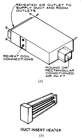
Fig. 56 Single-duct system with reheat coils (a) requires a simple terminal
where velocity and pressure are reduced. Box capacity ranges from 200 cfm (95
L/s) at 12 in. by 50 in. by 22 in. (305 x 1270 x 560 mm) to 5000 cfm (2360
L/s) at 20 in. by 60 in. by 80 in. (510 x 1520 x 2030 mm). (b) Electric coil
within a duct. Size varies to suit duct dimensions (and capacity, which can range
from 0.3 to 2000 kW).
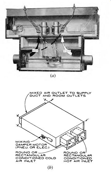
Fig. 57 High-velocity, dual-duct terminal providing mixing and attenuation
(pressure and sound reduction). (a) Controlled from a thermostat, this unit
blends the supply airstreams and delivers air to the zone at the selected temperature.
(b) Typical mixing box dimensions are: 10 by 50 by 30 in. (250 x 1270 x 760
mm) for a 400 cfm (190 L/s) unit to 18 by 60 by 66 in. (460 x 1520 x 1680 mm)
for a 5000 cfm (2360 L/s) unit.
6. AIR AND WATER HVAC SYSTEMS
These systems, introduced in Fig. 13 and Section 10.2, have the design complexity-and first cost-of supply-and-return distribution trees for both water and air. This disadvantage is offset by the space-saving advantages of thinner water trees, the possibility of only one air tree (supply), and the superior comfort characteristics offered by air. When only fresh air is centrally treated and distributed, only an equal quantity of air need be exhausted, which rarely needs an extensive distribution tree. Because this exhaust air is not recirculated, these systems are attractive for hospitals and other buildings in which the mixing of air between zones is undesirable. When return air is used rather than exhausted, it forms a small percentage of the supply air.
These systems are most often used in perimeter zones, where extensive extra heating (winter) and cooling (summer) is readily provided by water. If only one water supply tree is used (two pipe system), there is a problem of deciding when to change over between heating and cooling. In space maintenance is required (filters in particular), and humidity is less tightly controlled than in all-air systems. In most air and water systems, the air is circulated in a cooled and dehumidified condition and heated by the water for most of the year.
Air and water systems can often be found in the perimeter zones of office buildings, hospitals, schools, apartments, and laboratories.
(a) Induction
Centrally conditioned fresh air is supplied (at either high or medium pressures and velocities) to each induction terminal (Fig. 13a). Each terminal then mixes 20% to 40% incoming fresh air with the 80% to 60% room air that is induced to flow along with the fresh air, all passing over finned tubes for heating or cooling and circulating this mixture of air to the space.
In two-pipe systems, either hot or cold water- not both-is available to temper this air mixture ordered by the thermostat linked to each terminal.
Because cool air is distributed for most of the year, the two-pipe system is largely in heating mode (in colder climates).
In four-pipe systems, the availability of both hot and chilled water makes it possible to switch instantly from heating to cooling for excellent thermal control.
The induction terminals typically are located either below perimeter windows (Fig. 58) or above a suspended ceiling. Condensation from the cooling coil in summer and the need to clean the filters of the induced room air make under-window locations much easier to maintain, even if they intrude on the floor area available.
The CBS Tower in New York City (Fig. 59) uses a high-velocity induction system for its perimeter zones. The triangular black granite-faced exterior columns give the façade a three-dimensionality quite unlike the slick glass boxes of its contemporaries (it was designed by Eero Saarinen and built in 1962). These thick columns enclose the perimeter distribution trees; every other column contains the high-velocity air supply; in between, every fourth column contains the supply water and every alternate fourth column the return water trees. These constant column sizes belie the thicker air, thinner water distribution trees. The interior zone of this tower is served by a VAV system; return air from both perimeter and interior zones is collected at the core.
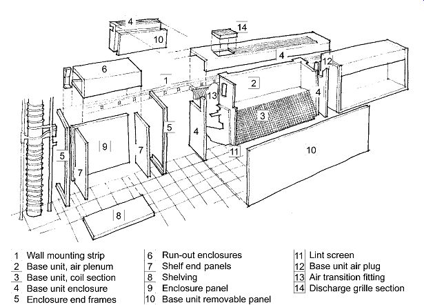
Fig. 58 Installation of a high-velocity induction unit. Conditioned 100%
outdoor air is brought in through a high-velocity duct to pro vide ventilation
and to induce the circulation of room air. It is attenuated and silenced in
the chamber (2), and then, through jets in the front of the plenum, it induces
the flow of room air, which is heated or cooled at the fin coil (3). The lint
screen (11) requires periodic maintenance for proper airflow.
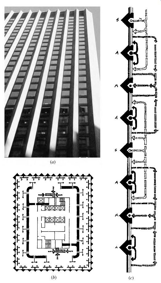
Fig. 59 The identical
triangular exterior columns of the CBS Tower in New York City (a) enclose a
variety of distribution trees. (b) Plan of a typical floor; perimeter zones
are served by a high-induction air and water system, interior zones by VAV.
All return air is collected at the core. (c) At the perimeter, column type
A contains an air supply tree feeding the high-velocity induction unit on either
side of the column. Column type S contains the supply water tree, hot in winter
and cold in summer. Column type R contains the return water tree. (From David
Guise, Design and Technology in Architecture)
(b) Fan-Coil with Supplementary Air
This system (Fig. 13b) is closely related to the preceding induction system; however, this system uses a fan at each unit, rather than high-velocity primary air, to move the mixture of supply and room air through the unit. A typical arrangement is a supply air plenum over a corridor, feeding horizontal fan-coils above the suspended ceilings of spaces on either side. These fan-coils draw some supply air and mix it with room return air to maintain desired temperatures. If condensation and resulting pans of standing water are to be avoided, the supply air must be sufficiently dehumidified.
Fan-coils are very widely used, both in con junction with conditioned supply air (air and water) or as stand-alone units that take in their own fresh air at the perimeter (all-water), or even as room-air only units. A building that uses both fan-coil units (at entries) and radiant panels (in offices) is shown in Fig. 60.
(c) Radiant Panels with Supplementary Air
Radiant heating systems (Fig. 13c) have a large following of comfortable users; radiant cooling systems are fairly commonly used in Europe and are getting a closer look in the United States.
Large areas of radiant surface can be used to offset large losses of bodily radiant heat, as in the case of large areas of cold glass on a winter day, or when users are both scantily clothed and sedentary. In summer, such panels can help offset radiant gain from electric lights or large glass areas. The ceiling is often favored for the panel location, because it is uncluttered by the furniture, tackboards, and other items that cover floors and walls. At the 56-story Commerzbank in Frankfurt, Germany, chilled ceilings serve all office floors in conjunction with the ventilation system.
Green on the Grand (Fig. 60) is a 23,465-ft 2 (2180-m^2) two-story office complex in Kitchener, Ontario. Its design combines a very highly insulated envelope, daylighting, water conservation, a gas absorption (non-CFC, non-HCFC) chiller/heater with a heat rejection pond, a separate IAQ system, and heat recovery of exhaust air. It also features a dedicated air system for ventilation and a hydronic system for heating and cooling. The hydronic system uses fan-coils for the entryways and radiant panels on ceilings of office spaces. (The conditioned air in this example is provided by the ventilating system.) Fan-coils are better able to handle the extremes of entryway heat losses and gains. The radiant panels in the offices are used for both heating and cooling, but are sized to meet cooling loads and cover 30% of the ceiling area. Tenants were given their choice of two designs: steel panels suspended below a drywall ceiling (painted to match the ceiling color) or extruded aluminum panels fit into a suspended ceiling system. To prevent condensation on these radiant panels during cooling, the ventilation air is dehumidified.
The ventilation system supplies low on the walls and exhausts high on the walls, a form of displacement ventilation. There are two rates of fresh air: 20 cfm (10 L/s) per person, and (when economizer cycles operate or when more fresh air or more cooling is required) 40 cfm (20 L/s) per person. The exhaust air then flows through two heat exchangers: the first reheats fresh air that has been greatly cooled for dehumidification; the second preconditions the incoming fresh air at the point of entry. The latter heat exchanger is a rotary wheel ERV capable of transferring both heat and moisture.
Several approaches to the radiant cooling (and heating) panel, independent of a dehumidified air supply, are shown in Fig. 61. These approaches assume a minimal floor/ceiling thickness, which could contribute either to reducing the floor-to-floor height or to greater ceiling height (for daylight penetration or displacement ventilation). If a raised floor is used above these concrete slabs, even higher percentage heat gains come from the ceiling.
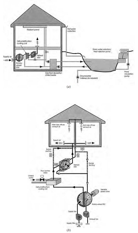
Fig. 60 An innovative Canadian office building, Green on the Grand at Kitchener,
Ontario. The cooling system combines a radiant panel system (a) with a dehumidified
summer ventilation system (b). The building also features daylighting, a gas
absorption chiller/ heater, rainwater pond heat rejection, and two-stage heat
recovery. (b)
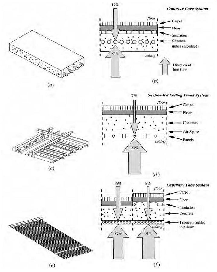
Fig. 61 Approaches to radiant cooling systems. (a) Concrete core system:
water is circulated through plastic tubes embedded in the concrete floor/ceiling
slab. (b) With carpet, pad, and insulation on the floor, most of the heat radiates
to the ceiling. (c) Panel system, usually using aluminum facing, connected
to metal tubes. (d) Panel system has the highest heat flow to the ceiling.
(e) Cooling grid made of capillary tubes embedded in ceiling plaster (or in
gypsum board or mounted on ceiling panels). This provides the most even surface
temperature distribution. (f) Again, a high percentage of the heat is radiated
to the cooled ceiling, depending on the use of insulation below the carpet
and pad.
Radiant cooled floors are sometimes used, as in the Bleshman Regional Day School (Fig. 62). The designers of this school for the handicapped recognized that the majority of its users would spend much of their time quite close to the floor and that the colder air near the floor could be uncomfortable, especially in the New Jersey winter. The entire floor is warmed by the supply (ventilation) air in winter, which enters just below windows to counteract the downdraft off cold glass. In summer, the cool sup ply air first cools the floor and then cools the air in front of the warm glass. The concrete cellular "air floor" provides a thermal mass that helps maintain steady temperatures. Heated or cooled air is pro vided by rooftop air-air heat pumps, one of which is provided for each cluster of three to six classrooms.
This HVAC example is therefore related to the direct refrigerant systems family.
(d) Water Loop Heat Pump
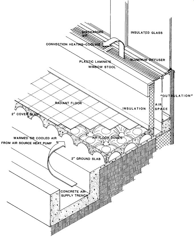
Fig. 62 Underfloor air distribution achieved with a cellular concrete air
floor serves the Bleshman Regional Day School in Paramus, New Jersey.
This approach was diagrammed in Fig. 9.45 and is used in the school shown in Fig. 51. In the 175,000-ft^2 (16,260-m^2) Comstock Center in Pittsburgh (Fig. 63), there are six to eight small heat pumps on each of 10 floors, located above the suspended ceiling. Their connecting loop doubles as the building's wet-pipe sprinkler system sup ply; this is possible because the heat pumps keep the loop between 65ºF and 85ºF (18ºC and 29ºC). Because neither hot nor chilled water supply and water return distribution trees are needed in addition to the sprinklers, there is a substantial first-cost saving, and relatively little building volume is consumed. A 23,000-gal (87,060-L) water storage tank allows daytime heat, rejected to the loop by the heat pumps, to be stored and recalled for nighttime heating. When necessary, penthouse equipment is used: two small boilers to maintain the 65ºF mini mum temperature in the water loop or an evaporative condenser to hold temperatures at 85ºF.
Another feature of the Comstock Center is its use of air extract windows (see Fig. 50) to control infiltration and to moderate the perimeter zone's temperatures. After the return air passes up inside this window and arrives in the ceiling plenum, it is mixed with fresh air, then tempered and recirculated by the heat pumps.
The Comstock Center also utilizes a large day lighting atrium, whose temperature control is pro vided largely by exhaust air from the offices; the stack effect is utilized to provide natural ventilation on its west face in summer conditions.
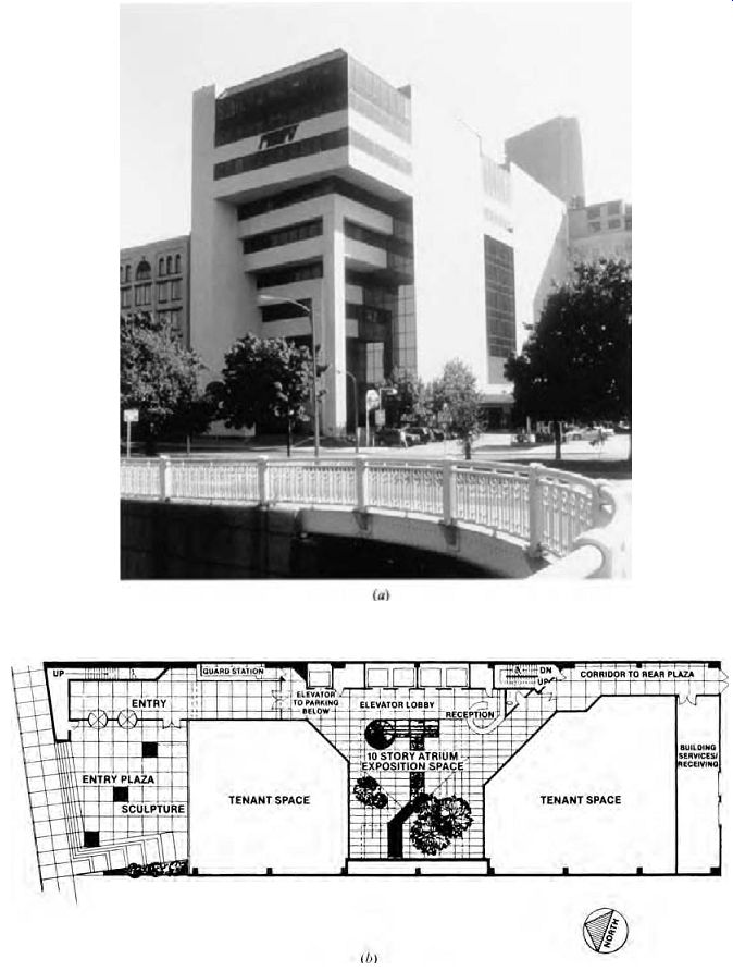
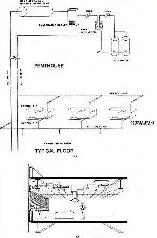
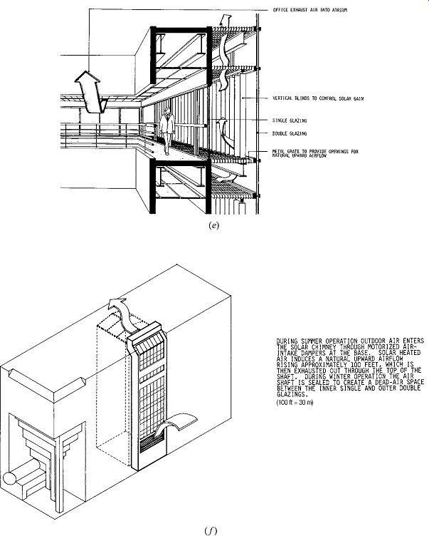
Fig. 63 The Comstock
Center, Pittsburgh, Burt Hill Kosar Rittelmann Associates, architects. (a)
The north and west faces. (b) Ground-floor plan. (c) Water loop heat pumps
are linked via the sprinkler system on each floor. This is also called a tri-water
system. (d) Extract-air windows (see again Fig. 50) control infiltration and
moderate the perimeter zone temperatures. Fresh air is ducted to the plenum,
where it mixes with return air before being treated and recirculated through
the heat pumps. (e) The central daylighting atrium is tempered by exhaust air
from the offices; exhaust air then leaves via the stack effect. (f) The stack
effect also controls summer overheating.
7. ALL-WATER HVAC SYSTEMS
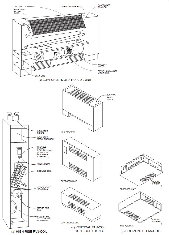
Fig. 64 (a) The innards
of a simple fan-coil unit without outdoor air connection; showing a standard
below-window unit. Widths can range from 2.5 to 7 ft (0.8 to 2.1 m), height
is around 26 in. (660 mm), and depth between 9 and 12 in. (230-305 mm). (b)
High-rise unit for corners or cabinet locations. These can be stacked to reduce
connecting piping runs and simplify condensate collection. (c) Vertical units
for below large windows. Low-profile unit height is around 14 in. (360 mm).
(d) Horizontal units for above-ceiling locations.
These systems (see Fig. 14 and Section 10.2d) typically deal only with temperature control; air quality is left to separate systems. An especially familiar all-water application is the simple fan-coil unit (Fig. 64). (Because units with the same name are used in air and water systems, this further blurs the distinction between these two HVAC families.) These units, which may be found above ceilings, below windows, or in corners, simply control the temperature (and, to a limited extent, the relative humidity) of the air already in the room, which is blown through the coils. Because water is often condensed from the room air when cooling is in progress, a drain line is required; water standing in drain pans is unhealthy. Exterior air intake grilles can easily be added when fan-coil units are located below windows to allow the local provision and tempering of ventilation air; this is especially common in motels, hotels, and apartments.
Fan-coil units are inherently noisy due to the fan, so careful attention to sound ratings is required when background sound levels must be low. In offices, a relatively high background sound level can help to maintain acoustic privacy at the work station; the sound of the fan-coil provides reassurance that some kind of air treatment system is at work.
All-water perimeter systems with local fresh air can also take the simple form of operable windows with hot water finned-tube radiation. An expressive variation on this approach appears in the reading rooms and staff workrooms for the Seeley G. Mudd Library at Yale University (Fig. 65). Limestone spandrels are curved in to allow fresh air to enter these smaller-perimeter rooms just below the windows, where hot water finned-tube radiators are available when needed. The incoming fresh air replaces exhaust air, which flows out of the upper operable windows. The remainder of the building has conventional forced-air heating and cooling.
8. DISTRICT HEATING AND COOLING
Often, large projects made up of many large buildings are well served by one central station heating/ cooling plant. The familiar economies of scale apply here; very large, efficient, and well-maintained boilers and chillers encourage energy recovery through heat exchange, reduce air pollution, and remove the noise and other nuisances associated with heating and cooling from the other buildings. This approach is called district heating and cooling.
District heating for residences and small commercial buildings is common in northern Europe; district steam systems serve the central areas of many U.S. cities. Most often, electrical generating plants are the heat (or steam) source; cogeneration (discussed in Section 10.9) allows the waste heat from the generating plant to be put to use either as space heating or steam (indirect-fired) absorption cooling. Ironically, the trend toward better-insulated buildings has reduced the market for distributed heat, making the installation less cost-effective. This discourages suppliers both from investing in a district system and from encouraging technical innovations in energy conservation by their customers. Smaller, densely built-up central heating districts tend to be more successful than large, sprawling ones; lengthy lines cost more to install and maintain and lose more energy.
(a) High-Temperature Water and Chilled Water
Long-distance steam distribution has been used for more than a century; the development of high temperature water (HTW) and chilled water distribution among buildings is a more recent development.
Offering many advantages (although steam is still frequently chosen for city distribution), circulated high-temperature, high-pressure hot water and chilled water in closed systems are widely used in U.S. Air Force bases and airports, and for groups of buildings such as hospital complexes and college campuses. Increased efforts are being made to install new district heating/cooling networks served by existing fossil-fueled electricity generating plants. Such plants waste more than half of their fossil fuel input, and district heating/cooling could intercept much of that waste; see also the next section on cogeneration.
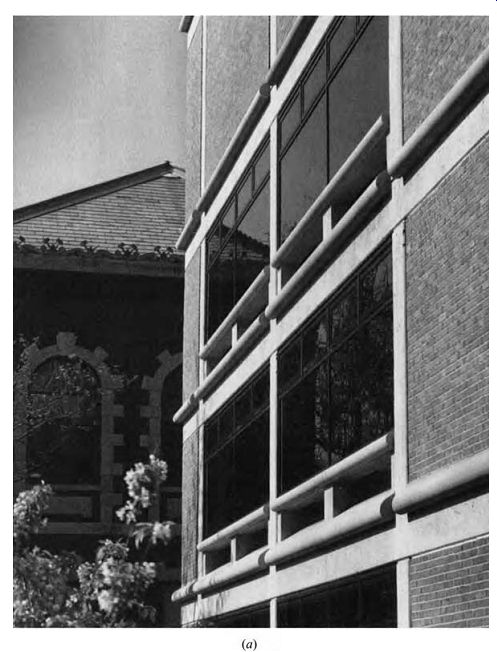
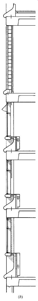
Fig. 65 Local fresh air and finned-tube radiation at the perimeter. The
Seeley G. Mudd Library at Yale University; Roth and Moore, architects. (a)
Exterior, showing curved limestone spandrels, along which flows incoming fresh
air. (b) Section showing the fresh air intake, finned-tube radiation, and upper
operable sash for exhaust air. This system is used for the smaller reading
room and staff workrooms at the perimeter.
Water will not flash into steam if kept at sufficiently high pressure. It may then be circulated by pumps through supply and return mains and through branches to heat exchangers, which operate conventional low-pressure hot water systems, generate steam, and perform numerous other thermal tasks. Pressures are on the order of 400 psig (pounds per square inch, gauge; 2758 kPa) and temperatures are about 300ºF (149ºC). During its circuit, the water will sometimes lose up to 150Fº (83Cº) and 60 psig (414 kPa) in pressure. The section shown in Fig. 66 illustrates a common arrangement.
High-temperature water has a number of advantages over steam for certain installations. It is a two-pipe system, and the temperature drop in the supply main is often as little as 10Fº (5.5Cº). With reasonably high water velocities, mains can be reduced to almost half the size of those required for steam distribution, with no need for steam traps and pressure-reducing valves. The pipes need not pitch to low points, as in the case of steam (to accommodate condensation), but can follow the contours of the ground. Although installation costs are greater, operational costs are less than those for steam.
Feed water treatment is negligible and corrosion is minimal. Underground problems of expansion and insulation are the same as in other subterranean systems. Large sweep-type loops accommodate expansion between fixed points, and underground piping is embedded in special thermally efficient insulative fill.
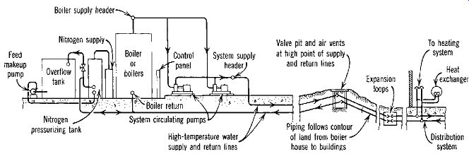
Fig. 66 Typical arrangement of a high-temperature water system.
District chilled water systems also offer advantages. The remote central chillers are likely candidates to use waste heat in a non-CFC absorption cooling cycle. Natural sources are possible; the Toronto (Canada) District Heating Corporation uses Lake Ontario water, drawn from a 1.6-mile (2.6-km) intake at a depth of 200 ft (61 m) with a year-round temperature of 40ºF (4.5ºC). Passed through a heat exchanger (with the district chilled water) and then treated, the lake water then joins the city water supply.
With district heating/cooling, all facilities except air handling and ducts are located together in a remote central plant. This frees the buildings from the space requirements and visible impacts of stacks, boilers, fuel storage, water chillers, and cooling towers; the associated heat, humidity, fouled air, and noise are as remote as the central plant.
When such a system serves individual customers, the heated or chilled water is metered. When it is owned by the group of buildings served (such as college campuses), it is usually not metered; this can become a problem when efforts to identify building energy waste and subsequent savings are being investigated.
9. CO-GENERATION
In the preceding Sections, electricity has repeatedly been called a high-grade source in reference to the high temperatures needed to produce electricity by conventional (fossil-fuel) means and to the large amount of waste heat (often twice the fraction of electricity) produced in the process. Cogeneration (also called total energy) is an attempt to recover some of the otherwise wasted lower-grade heat that accompanies the generation of electricity by steam turbines. Industrial cogeneration facilities are especially cost-effective in the pulp and paper, petroleum, and chemical industries. Building-scale cogeneration is a less obvious energy bargain.
(a) Electrical Power Generation at the Site
Where conditions are favorable, electricity for power and light can be generated economically by a system that also supplies the building with heating in winter and cooling in summer. Such a system utilizes a fuel such as gas or oil and is often supplemental to the local electric utility company.
Although installation costs are greater than those for the more conventional systems that use separate services of electricity and fuel, the savings in annual operating costs can sometimes pay for the excess installation cost in a reasonable time. Operational savings continue thereafter. This approach was developed largely in the 1960s and is used in hundreds of commercial and industrial buildings and in many schools. Cogeneration is particularly attractive for district heating/cooling plants.
(b) Early On-Site Power Generation
Before 1900 and for several years thereafter, nearly all large buildings and groups of buildings were supplied with direct current generated on or near the premises. The motive power was usually in the form of steam-driven reciprocating engines with belt connections to direct-current generators.
Direct current cannot be transformed to different voltages and must be generated and distributed at the voltage used in the building. At these relatively low voltages, power loss in the distribution system is great, and distance adds greatly to the loss. This tended to keep electricity within a building.
With the development and use of alternating current machines, utility companies were able to establish central power stations from which electricity could be transmitted great distances to the user at high voltage. There it was transformed down to lower voltages for use. Because, at high voltage, power losses are very low, this system became universal. During the 1920s and 1930s, owners removed their private power generators and accepted utility service, with its savings in operating expense.
(c) How Cogeneration Developed
Older buildings used steam produced from coal burning boilers from which little or no energy salvage was possible. Today's fuels, used directly in reciprocating engines or turbines (including those that generate electricity), have residual heat value that can be recovered for purposes of heating or cooling. For cogeneration to be successful, there should be a reasonably steady demand in the building for the power generated and also for the heat recovered. Lighting and the demand for power by computers, electrical business machines, and other devices can create nearly constant demand for power throughout the year. Similarly, the exhaust heat recovery from the engines or turbines that power the generators is in demand for either heating or indirect-fired absorption cooling at most times of the year.
(d) Turbines and Reciprocating Engines
Figure 67 shows two principal systems for total energy. In both systems-one using a turbine and the other a reciprocating engine to operate the generator that supplies electric power-heat is reclaimed to produce steam or hot water. The steam or hot water is then used for heating or, by use of an absorption chiller, for cooling. When a turbine is used, the fuels are natural gas or fuel oil.
The heat is recovered by passing the hot turbine exhaust through a waste heat boiler to produce steam. Fuel for a reciprocating engine is natural gas or diesel fuel. Both the jacket cooling water and the hot engine exhaust are passed through heat exchangers that utilize the heat to produce steam or hot water for heating or cooling. In both systems, an auxiliary boiler, fired directly by gas or oil, stands ready to help maintain a balance in the system.
Cogeneration offers a degree of electrical independence and a way to use otherwise wasted heat.
The latter is essentially free energy because it would otherwise have to be purchased and paid for separately in the form of electricity or other fuels.
(e) Cogeneration for Housing
The Harbortown apartment and townhouse complex in Detroit, Michigan, utilizes a year-round natural gas-fired primary energy and cogeneration/ waste recovery system (Fig. 68). Each apartment has one or two stackable, upright fan-coil units using either chilled or heated water. This water is provided by two direct-fired chiller-heaters: each incorporates a natural gas boiler and a two-stage absorption chiller in the same unit, taking less space in the mechanical room. The natural gas-driven cogeneration electric plant serves rather constant loads such as corridor and outdoor lighting. The generator's waste heat is passed to a storage tank, where it preheats domestic hot water for the tenants. This meets about 87% of the hot water energy usage.
(f) Fuel Cells
We first encountered fuel cells in connection with the explorations of outer space. Spaceships use stored oxygen and hydrogen to feed the fuel cell, yielding-seemingly miraculously-electricity, heat, and pure water. In effect, this reverses the process of electrolysis: using electricity to split water into its two components, hydrogen and oxygen. This theory dates back to Sir William Grove in 1839, long before the needs of space travel.
A fuel cell generates direct-current power by converting the chemical energy of hydrogen and oxygen into electricity and heat. Because no combustion is involved, nitrogen oxides and carbon monoxide are nearly eliminated. For a building based fuel cell power plant, several components are added: first, a fuel processor (or fuel reformer) to prepare a hydrogen-rich stream of fuel, then the fuel cell stack, then a power conditioner (or inverter) to convert the fuel cell's direct current to alternating current.
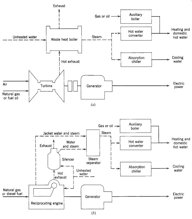
Fig. 67 Cogeneration (total energy) systems. (a) Using a turbine. (b) Using
a reciprocating engine.
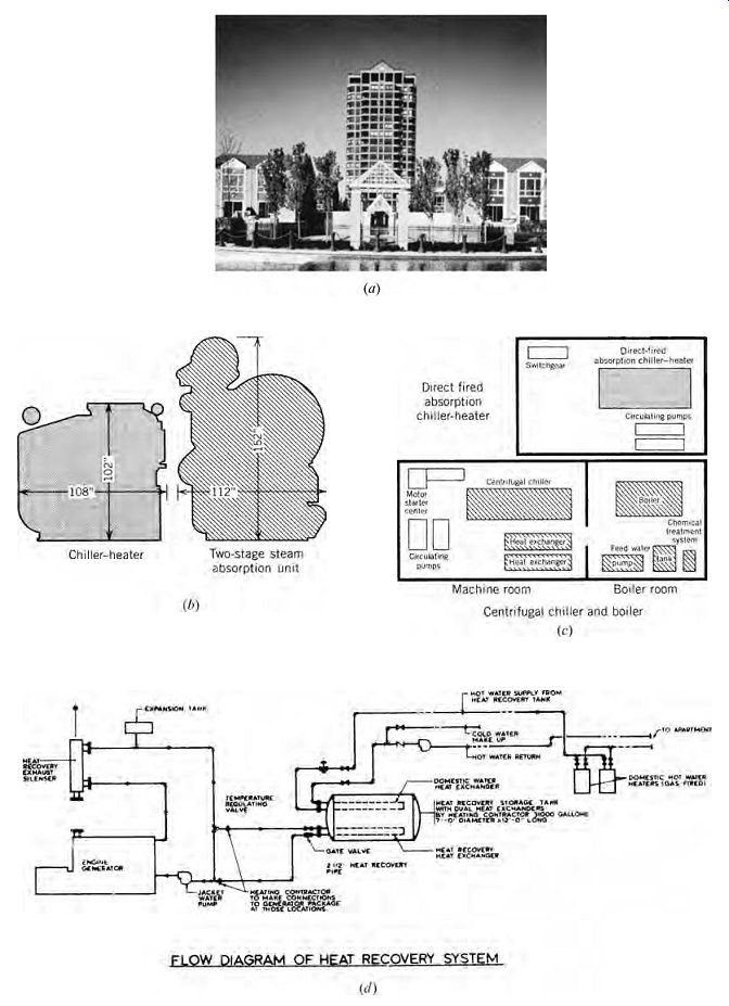
Fig. 68 Harbortown is a 120,000-ft^2 (11,150-m^2) apartment and townhouse
complex (a) in Detroit that uses natural gas as a primary fuel year-round.
Chiller-heaters ( Hitachi) combine a boiler and a two-stage absorption chiller
in one compact unit. (b) Comparison of headspace and (c) floor space required
by chiller-heaters versus conventional absorption chiller of similar capacity.
(d) Cogeneration plant sends its waste heat to preheat domestic hot water.
Fuel cells are not, by themselves, that much more efficient than combustion processes; they are about 40% efficient for power production. When combined with a way to use that 60% waste heat, they climb toward a total of 90% efficiency, with very few harmful emissions.
Hydrogen is the ultimate fuel; already hydrogen-rich, it needs no processor and produces the least environmental impacts from the fuel cell.
Although hydrogen supply networks are not yet commonplace, scenarios exist for a "hydrogen economy" in which surplus electricity from wind power is used to split water into hydrogen and oxygen atoms and the hydrogen is stored for later distribution. Windpower's extreme variability often presents power grid distribution challenges; storage solves this problem. Solar energy or biomass are other renewable sources for electrical generation.
However, other hydrocarbon fuels also can feed fuel cells: natural gas (most common for building fuel cell power plants), propane, methanol, and, with additional pretreatment, methane from landfills and anaerobic digester gas from sewage treatment plants. Even with these less hydrogen-rich fuels, the emissions from fuel cells are well below those of combustion processes; the fuel processor emits car bon dioxide and a trace of carbon monoxide.
Proton-exchange membrane (PEM) fuel cells (Fig. 69) are promising for transportation when zero-emission vehicles are the objective and hydrogen is available as the fuel. This process has building applications as well. It works at a temperature below the boiling point of water. Relative to other fuel cell types, it has a smaller size, lighter weight, and lower noise levels. The PEM fuel cell stack involves several subsystems, typically including water purifiers and pumps, air compressors, and heat rejection components (coolant pumps and a radiator). This complicates performance at subfreezing temperatures and adds maintenance requirements. But the smaller size promises smaller building applications in the future.
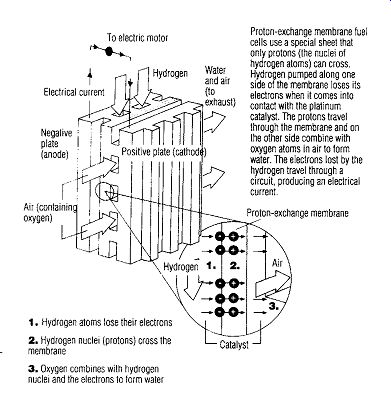
Fig. 69 Schematic diagram of a proton-exchange membrane (PEM) fuel cell
with a description of its operation.
The phosphoric acid fuel cell power plant (Fig. 70) is at work in (or outside) a number of buildings and municipalities around the world. The ONSI Corporation's 200-kW fuel cell power plant measures 10 ft × 18 ft, is 10 ft high (3 m × 5.5 m, 3 m high), weighs 40,000 lb (18,144 kg), and needs a clearance of 8 ft (2.5 m) around the module for maintenance. It also needs a cooling module (or a building's cooling tower) for discharge of heat in excess of that recovered for building use. The acid electrolyte in the fuel cell stack works at about 390ºF (200ºC). At its rated power, it also produces 700,000 Btu/h (205 kW) to heat a water stream to 140ºF (60ºC). The rated sound level is 62 dBA at 30 ft (9 m) from the module.
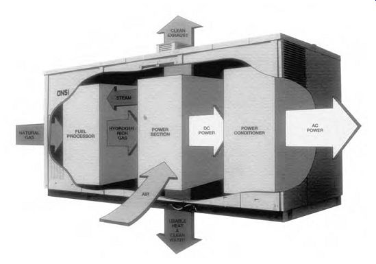
Fig. 70 A fuel cell power plant using natural gas (or other hydrocarbon
fuel). The fuel processor (reformer) converts the natural gas to a hydrogen-rich
stream that enters the fuel cell power section (or stack). The output is electricity
(dc), water, carbon dioxide, and considerable heat. Some heat is used by the
fuel processor and some is rejected, but most is usable in a building or industry.
A power conditioner (inverter) converts dc to ac power.
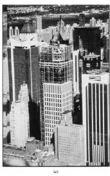
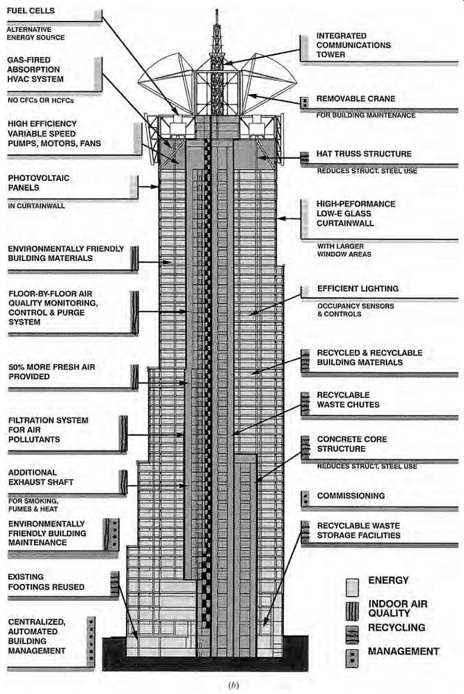
Fig. 71 The 48-story office building at 4 Times Square, New York City (a),
shown under construction in 1998. (b) Many environmentally friendly features
are included, such as façade-integrated PV and two fuel cell power plants like
those shown in Fig. 70. Fed by natural gas, the fuel cells are expected
to work without maintenance interruptions for up to 5 years and pro vide considerable
hot water as well as electricity. (The fuel cells are actually installed at
the fourth-floor level rather than at the penthouse as shown.)
The Durst Organization's high-rise office building at 4 Times Square in New York City (Fig. 71) is a demonstration of several future-oriented strategies: PV cells integral to the façade, direct-fired (natural gas) absorption chillers, increased fresh air for IAQ, a dedicated exhaust air shaft (for smoking and other polluting activities), and waste chutes to facilitate recycling, among others. It also utilizes two 200-kW fuel cell power packages fed by natural gas. The electricity is about 80% destined for external lighting by night; huge electrical signs will be a prominent part of the building's Times Square façades. By day, about 80% of the power goes to the building's base load. The hot water will be used in winter for perimeter heating. In summer, the water is wasted. Although there was hope that one of the absorption chillers could be fed by this water, a variety of considerations precluded this: the fuel cells are located on the fourth floor (accessible to maintenance and close to the huge signs), whereas the chillers are located in the penthouse.
The 200-kW fuel cell in Fig. 70 is usually fed by natural gas, but other examples include hydrogen fuel (Hamburg, Germany: electricity to the grid, hot water to heat an apartment building), anaerobic digester gas (Yonkers, New York: waste water treatment plant; electricity and hot water used within the facility), and landfill gas (Groton, Connecticut: closed landfill; electricity to the grid, plans for a hydroponic tomato-growing green house to utilize the hot water). Plentiful hot water is a by-product of the fuel cell; it seems that finding a year-round use for this water is often a problem of excess supply.
Other fuel cell types include alkaline (operates at 480ºF [250ºC]), molten carbonate (works faster at 1110 to 1300ºF [600 to 700ºC]), and solid oxide (1200 to 1830ºF [650 to 1000ºC]) with a higher efficiency, and waste heat sufficient to run gas turbines. These higher-temperature processes are more applicable to central station power plants. Clearly, cogeneration and fuel cells have a promising future.
References and Resources
AIA. 1994. Ramsey, C. G. and H. R. Sleeper. Architectural Graphic Standards, 9th ed. American Institute of Architects/John Wiley & Sons. New York.
Allen, E. 1989. The Architect's Studio Companion. John Wiley & Sons. New York.
Allen, E. and J. Iano. 2007. The Architect's Studio Companion, 4th ed. John Wiley & Sons. New York.
ASHRAE. 2008. ASHRAE Handbook-HVAC Systems and Equipment. American Society of Heating, Refrigerating and Air-Conditioning Engineers, Inc. Atlanta, GA.
Grondzik, W. (ed.). 2007. Air-Conditioning System Design Manual, 2nd ed. American Society of Heating, Refrigerating and Air-Conditioning Engineers, Inc. Atlanta, GA.
U.S. Environmental Protection Agency, Energy Star Labeled Heating and Cooling Equipment
Prev. | Next
Home Similar
articles top
of page