| PREV.: Schematic Legend | NEXT: Pressure Relief Valves | Article Index | Home |
AMAZON multi-meters discounts AMAZON oscilloscope discounts The sheer existence of the world in which we live, depends on the interaction and the balancing of forces. From baby’s first breath, to the complex network of forces holding our solar system together, forces are constantly acting and re acting to keep energy in equilibrium. From the beginning of time, man’s unyielding quest to understand and to manipulate the interaction of forces has made our world a better place. Basic physics can show how pressure relates to force in a hydraulic system. This section will be devoted to an understanding of various pressure controls, and of how we can manipulate forces through the use of hydraulics. |
In general, there are five basic functions which can be performed by pressure-control valves, namely:
Relief Valves: First, limit the maximum system pressure which, in turn, protects system components, piping and tubing; and second, limit the maximum output force of the hydraulic system.
Reducing Valves: are used to limit a certain branch of the hydraulic circuit to a pressure lower than the relief valve setting for the rest of the system. By reducing pressure in the secondary circuit, we can independently limit the out put force to that in the primary circuit.
Sequence Valves: are used to assure that one operation has been completed before another function is performed. They operate by isolating the secondary circuit from the primary circuit until the set pressure is achieved. The flow of fluid is then sequenced from the first to the second circuit. Primary pressure must be maintained for the secondary function to be performed. Sequence valves establish an order for the interaction of forces.
Counterbalance, overcenter or brake valves: are a broad range of pressure valves which control a load induced pressure to hold and control the motion of a load. This group of valves provides balancing forces which prevent the load from running away because of its own weight or because of inertia.
Unloading Valves: are usually used in circuits with two or more pumps incorporating accumulators. The valve operates by sensing pressure in the s downstream of a check valve. Once a certain pressure level is obtained, the unloading valve unloads its pumps to tank. The check valve isolates the unloaded pump from the rest of the system. System pressure is then maintained by the accumulator or by a smaller volume higher pressure pump.
BASIC PRESSURE VALVE OPERATION
All types of pressure valves function by balancing a hydraulic force with a spring force. You will notice that from the simplest direct operated design to the most sophisticated pilot operated model, the spool, poppet, or ball is held in position by an adjustable spring. Opposite this spring force is an area which is exposed to system pressure.
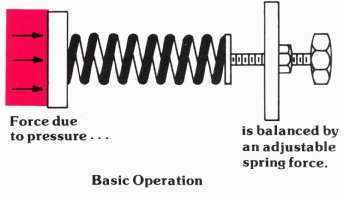
Above: Basic Operation: Force due to pressure...is balanced
by an adjustable spring force. (Color
code legend)
We know that force due to pressure is:
Force = Pressure [(lbs)/(in)2] x Area (in)2 = lbs.
To balance this force, we use a spring which can be com pressed by some adjustable mechanical means. Compression springs exert a force proportional to the amount they are compressed. Depending on the stiffness of the spring, the increase in force can be very high per inch of compression, or it can be very low. For any given spring, a numerical value is assigned which indicates the spring stiff ness. This value is called the spring constant and has the units (lbs /in). Consequently,
Spring Force = kX
Where: k = Spring Constant
X = Compression length (in.)
PRESSURE CONTROLS MUST MODULATE
Since any pressure control must handle a dynamic flow of fluid, it must modulate to maintain the balance between the spring and the hydraulic force. When functioning, these valves are in constant motion (internally) at one of the many positions between fully open and fully closed. In this way, they pass just enough fluid to keep the system pressure at valve setting.
With the understanding that all pressure valves balance a hydraulic force by a spring force in a dynamic condition, we now wish to discuss, in detail, the various valve types.
| Top of Page | PREV.: Schematic Legend | NEXT: Pressure Relief Valves | Article Index | Home |