| PREV.: Introduction and Basic Pressure Valve Operation | NEXT: Terms | Article Index | Home |
AMAZON multi-meters discounts AMAZON oscilloscope discounts
(See Color code legend for
above image)
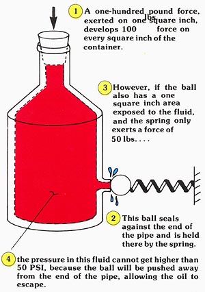
The purpose of a relief valve is to limit the maximum pressure in the system to which it is connected. Although pressure is generated by the load, the hydraulic pump is the energy input. Since we want to limit the energy source, the inlet of the pressure relief is usually piped into the hydraulic circuit as close to the outlet of the pump as possible. The valve is piped in parallel to the pump, which gives the output of the pump two possible flow paths, either to the system or over the relief, depending on which is the path of least resistance.
The relief is a normally closed valve which keeps the flow of fluid in the system until its pressure setting is reached. Once the valve opens and oil flows through it, energy in the pressurized fluid is expelled in the form of heat. Pressureless fluid from the relief valve’s outlet is then returned to the reservoir through the tank port connection.
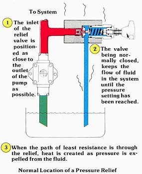
Above: Normal Location of a Pressure Relief. (Color
code legend)
A second source of energy input which often must be limited by the relief is that generated by the inertia of the load.
As shown in the two examples, the load can also be an energy source which must be limited to prevent damage to the system components or piping. The system can be protected from shock loading or inertia overloading by using either a port or crossport relief between the actuator and the rest of the hydraulic circuit.
Port reliefs are piped into the hydraulic system at the actuator the same way main system reliefs are piped into the system at the pump. Any pressure overload in the service line to which they are connected is simply relieved to tank at valve setting. In some applications, other circuit precautions must be taken to prevent cavitation in the low pressure side of the actuator. As shown in the example, a make-up check allows the actuator to draw oil from the reservoir as the piston is displaced downward.
A second way of preventing cavitation in the actuator is sim ply to relieve its outlet port to its inlet. During the overrunning load condition, the actuator actually becomes a pump, drawing oil into its inlet and pumping pressurized fluid out of its outlet. A crossport relief valve simply adds resistance to flow as it short circuits the outlet and inlet of the actuator. Although this works satisfactorily only with actuators which have equal displacements in both directions of operation (double rod cylinders, motors, and rotary actuators), cross port reliefs are almost mandatory when the rotary motion of a hydraulic motor is blocked by a closed center directional control.
In selecting a valve to be used as a port or crossport relief, choose one which responds quickly and has little or no leakage when seated. Reliefs used in these applications should be set at least 150 PSI higher than maximum load induced pressure. This assures that the relief will not influence normal operation of the system, while, at the same time, it will provide relief protection the moment pressure rises above that induced by the load. One last precaution for crossport applications: a relief must be chosen which can withstand full system pressure on its tank port. By studying the previous example, you can see that under normal system conditions the tank port is exposed to full load induced pressure.
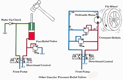
Above: Other uses for Pressure Relief Valves. (See
Color code legend for above image)
| Top of Page | PREV.: Introduction and Basic Pressure Valve Operation | NEXT: Terms | Article Index | Home |