AMAZON multi-meters discounts AMAZON oscilloscope discounts
UNDERSTANDING HEAT FLOW IS fundamental to all aspects of climate control. Section 4 addresses heat flows to and from the body that affect thermal comfort. Sections 8, 9, and 10 deal in part with heat flows to, from, and within various elements of active and passive climate control systems. This Section deals with heat flows through building envelopes, both through the materials of the building skin and by way of outdoor air that replaces conditioned indoor air. Basic concepts and calculations of heat flow are presented in this section, whereas applications of these concepts (passive solar heating, passive cooling, active HVAC system/equipment sizing, seasonal energy usage) are found in subsequent Sections.
1. THE BUILDING ENVELOPE
From a building science perspective, the exterior enclosure (or envelope) of a building consists of numerous materials and components that are assembled on site to meet the intents of the owner and the design team. A building envelope typically includes some prefabricated components (such as windows and doors) that are available off the shelf and have well-defined and tested thermal performance characteristics. The typical envelope also includes materials in a variety of forms (sheets, blocks, bulk products, membranes, etc.) that have been site-assembled to meet design requirements.
These components and materials may be assembled into commonly used configurations with generally understood performance or into configurations unique to a given project and of uncertain performance. The job of envelope thermal analysis is to ensure that a proposed envelope will meet the design intent and criteria (including building codes).
From a functional perspective, the envelope of a building is not merely a two-dimensional exterior surface; it is a three-dimensional transition space-a theater where the interactions between outdoor forces and indoor conditions occur under the command of materials and geometries. Sun and daylight are admitted or rejected; breezes and sounds are channeled or deflected; and rain is repelled or collected. This transition space is where people indoors can experience something of what the outdoors is like at the moment, as well as where people outside can get a glimpse of the functions within. FIG. 1 shows an example of an envelope that is a transitional space, not merely a surface. The more suited the outdoors is to com fort, the more easily indoor activity can move into this transition space. At building entries, a person will be especially aware of the difference between indoors and outdoors during the passage between the two conditions.
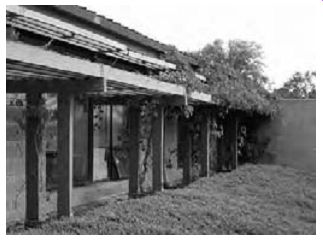
FIG. 1 The envelope is more than a surface. This south facing office façade
in Oregon forms a microclimate zone that buffers the transition between indoor
and outdoor conditions.
Groundcover plants at eye level for seated occupants and deciduous vines overhead give a seasonally changing view to the outdoors through a façade that also admits winter sun, year-round daylight, and summer breeze. (Amanda Clegg.)
The envelope has a fourth dimension: it changes with time. Seasonal changes have a marked effect on the façade shown in FIG. 1 and a more subtle effect on the east-facing balconies of the apartments in FIG. 2. The year-round usable volume of these apartments is increased by making the balcony into a sun porch. This allows sun to enter while blocking the wind-a response to Oregon's long, mildly cold winter. The more that users are involved in decisions about how much of the outside to bring inside, the more changeable the building envelope will be. Not all buildings encourage such flexibility and individual expression; an unchanging envelope can be a symbol of stability and may be considered appropriate for some governmental and religious monuments.
2. BUILDING ENVELOPE DESIGN INTENTIONS
Called by their familiar names, the basic components of a building envelope include windows, doors, floors, walls, and roofs. On closer inspection, windows can include skylights, clerestories, screens, shutters, drapes, blinds, diffusing glass, and reflecting glass-an array of components that determines how the envelope does its job of making the transition between inside and outside. Norberg Schulz (1965) suggests that a component can more fundamentally be thought of in terms of its design intent relative to the exchange of energies: as a filter, connector, barrier, or switch:
In general, we define a connector as a means to establish a direct connection, a filter as a means to make the connection indirect (controlled), a switch as a regulating connector, and a barrier as a separating element. . . . An opaque wall thus serves as a filter to heat and cold, and as a barrier to light. Doors and windows have the character of switches, because they can stop or connect at will. In addition to these historic envelope intents, a new option is emerging: the transformer. A trans former is intended to convert an environmental force (such as solar radiation) directly into a different and desirable energy form (such as electricity). A photovoltaic roof shingle is an example of a trans former.
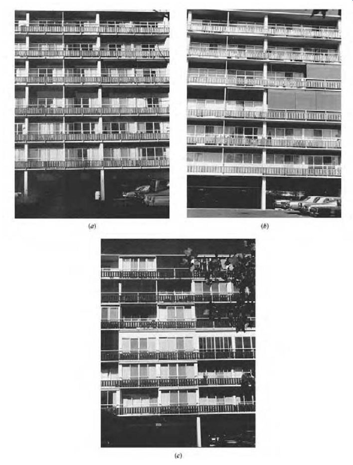
FIG. 2 Envelopes change
with time. This east-facing Oregon building façade changes by season and over
the years. (a) December morning sun floods unshaded balconies in the building's
early years. (b) Months later, June morning sun is blocked by shading devices
on some balconies. (c) Years later, many balconies have been enclosed for greater
winter comfort.
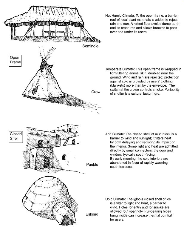
FIG. 3 Open frame (Seminole and Crow) and closed shell ( Pueblo and Eskimo)
envelope approaches are influenced by climate, materials, and culture. The
influence of climate is dramatic, but material availability and cultural expectations
also influence the envelope design solutions in these examples.
The fundamental range of choices surrounding envelope intent and components can be illustrated by two opposite design concepts: the open frame and the closed shell. In harsh climates (or where unwanted external influences such as noise or visual clutter abound), the designer frequently conceives of the building envelope as a closed shell and proceeds to selectively punch holes in it to make limited and special contacts with the out doors. Such an approach might be called barrier dominated. When external conditions are very close to the desired internal ones, the envelope often begins as an open structural frame, with pieces of building skin selectively added to modify only a few outdoor forces. Such an approach might be called connector-dominated. (Note that a connector, filter, or barrier for one natural force may change its role for another force: glazing may be a connector to daylight but a barrier to wind.) The open-frame or the closed-shell approach to envelope design, when combined with material availability and the influence of local culture, can produce a distinct regional architecture, as shown in FIG. 3.
With a wide range of energy sources, building materials, and mechanical equipment available, it is possible to build connector-dominated buildings anywhere, regardless of the climate. The con sequences of the resulting energy consumption can be severe. In contrast, if defending against outdoor conditions becomes an overriding consideration, barrier-dominated envelopes may be appropriate in any climate. The designer's use of connectors, filters, and barriers is basic to the design of building exteriors. With the addition of switches that allow the envelope to respond to changing conditions and transformers that respond to building needs and site resources, a liveliness can result that makes a building an attractive addition to its environs.
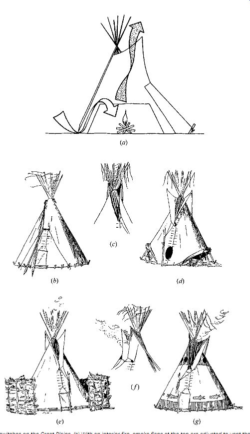
FIG. 4 Thermal switches on the Great Plains. (a) With an interior fire,
smoke flaps at the top are adjusted to vent the smoke, and an interior liner
forces the cold combustion air entering at ground level to first rise along
the sides of the tipi, gaining some warmth, before it moves across the occupants
on its way to the fire. Six adjustments to the lightweight, translucent, and
portable tipi are shown: the tip is in these diagrams are facing east, with
their backs to the prevailing westerly winds. (b) In severe rainstorms, the
smoke flaps at the top can be closed. (c) For ordinary conditions of west wind,
the smoke flaps block the wind, thus creating suction to draw out the smoke.
(d) In hot weather, breezes are admitted under the cover at the ground. (e)
In extremely cold weather, a temporary windbreak can be added. (f) For the
unusual wind or (g) southwest wind, the smoke flaps are manipulated to block
wind, again encouraging smoke draw-out, as in (c).
Switches are a designer's way of having an envelope respond in a variable manner and/or giving building occupants some control of their own environment. Seasons and functions change; people are unpredictable. If the designer has care fully considered the range of choices that a switch will provide, successful user control of that switch is possible. Building skins plentifully supplied with switches become demonstrations that architecture is a performing art, not simply static sculpture.
FIG. 4 shows a remarkably integrated switch dominated envelope in vernacular architecture.
Daylighting/solar control devices are perhaps the most common and visible switches. Awnings block direct sun at some times and admit it at others. Opaque drapes can expose all of a window to incoming daylight on dark days or block out day light entirely when desired. Translucent curtains can change bright sun into a diffuse light for the interior, or be drawn back to allow strong direct sun and shadow to be cast inside a room. Passive solar heating systems rely on switches to control the incoming sun on warmer days, as seen in FIG. 2b.
Operable windows are a commonly used thermal switch. Ventilating switches may be separate from windows.
Visually, switches are a particularly promising source of three- and four-dimensional interest on a building's exterior. For the office buildings in FIG. 5, on which façade would the daily and seasonal changes be most visually evident? If it is easier to imagine human beings working behind the windows of one building than of the other, might that suggest a more satisfactory work environment? Might more personal control of a window promote greater comfort? Switches encourage interaction between users and their environments. This is usually satisfying to the users, who are able to select the desired expo sure to the climate at a given moment. Yet without automation, supervision, or training in their use, switches can also be detrimental to system performance. Examples include a thermal shade left to cover a passive solar-collecting window on a cold, sunny morning; a vent left open during the hottest hours in a high-mass, night-ventilated building; or an awning rolled up to expose a window to summer sun. People in buildings often use switches as they feel appropriate, as demonstrated in FIG. 6.
Conventionally air-conditioned buildings typically do away with user-operated ventilating switches (operable windows) so that the system will instead function with a closely and automatically controlled flow of filtered outdoor air. Thermally efficient as this practice may be, it can also be a source of wide spread dissatisfaction with air-conditioned spaces.
Sealed windows greatly curtail people's contact with sounds, smells, and breezes from the outdoors.
This is frequently beneficial in urban areas, yet on beautiful days it can be very frustrating. A lack of switches can contribute to a feeling of helplessness about one's personal environment.
Passive heating and cooling systems are especially reliant upon switches, hence on the knowledge and cooperation of their users. These users often must base their actions in manipulating thermal switches at some point in time on what effect will be needed at a later time. This practice, called thermal sailing, is similar to the actions of outdoor workers in the far north, who learn to unbutton their coats in the cold early hours of the workday before they begin to sweat. Sweat would soak their insulating clothing, with harmful results later in the day as temperatures fall rapidly near dusk.
Misjudgments in passively solar-heated residences can result in extraordinarily high temperatures on a sunny day or uncomfortably cold nights without stored solar heat. For a building closely connected to its climate, the design of switches is also the design of an educational process for the users. The challenge is to involve, but not bind, the users in the management of their environment.
Automated controls are a partial answer to this challenge; switches that are easy, fun, and obvious to use are another.
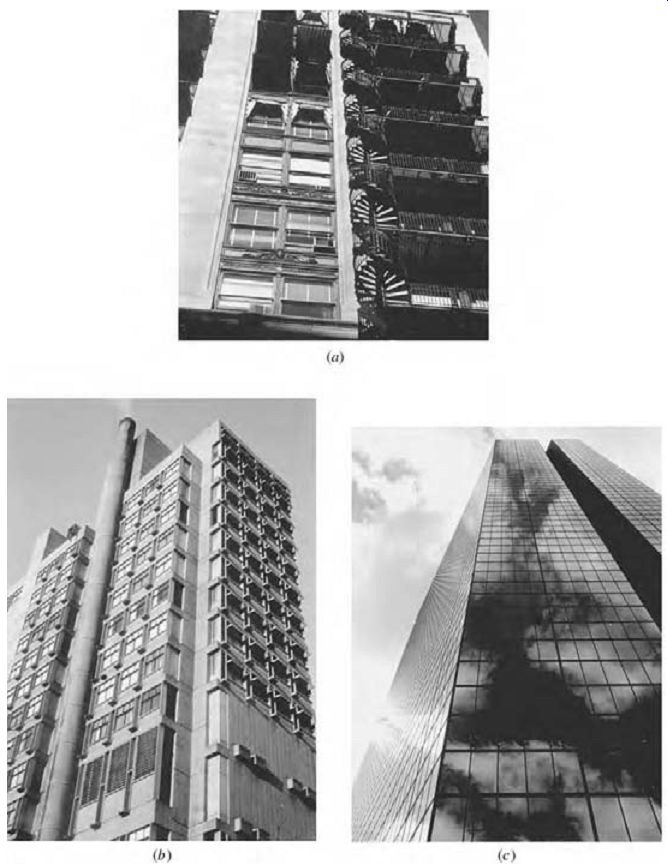
FIG. 5 Sun control for Boston offices. (a) Shading switches both inside
the glass (blinds) and outside the glass (awnings) are evident, and the windows
themselves are operable. Awning use varies with window location and occupant
needs and desires. (New England Merchants' Bank; Shepley Rutan & Coolidge,
Architects; demolished 1966.) (b) Three-dimensional filters (overhangs) dominate
the south façade (right) of this building at Boston University; the adjacent
west windows (where overhangs are less effective) have only internal switches
(blinds) deployed in a variety of positions. (Law and Education Building; Sert,
Jackson and Gourley, Architects). (c) A two-dimensional filter of reflective
glass equally sheathes all faces of this office tower, sending reflected sunlight
to the neighborhood below. The "switches" in this case are thermostats;
variability is removed from the envelope, and users are not involved in defining
the outside-inside relationship. (John Hancock Headquarters; I.M. Pei and Partners,
Architects; Stephen Tang.)

FIG. 6 Which is spring, which is summer? The awnings for this south-facing
office in Eugene, Oregon, are teamed with overhangs and side walls (or fins)
to provide sun control for windows. (a) The altitude of the spring sun is low
enough to threaten glare in the lower windows and cause awning deployment.
(b) The summer sun, at a higher altitude, is readily blocked by the overhangs,
and the awnings can be rolled up with less risk of glare. (Moreland-Unruh-Smith,
Architects.)
3. SENSIBLE HEAT FLOW THROUGH OPAQUE WALLS AND ROOFS
The flow of heat through a building envelope varies both by season (heat generally flows from a building in winter and to a building in summer) and by the path of the heat (through the materials of a building's skin or by way of outdoor air entering the interior through intentional and unintentional pathways). These complexities must be considered by a designer who intends to deliver comfort and energy efficiency. The following discussion of heat flow will focus first upon the building skin (opaque elements, then transparent elements), followed by heat flow via air exchange.
In the 1970s, designers began placing increasing emphasis on thermal performance of the building skin to conserve energy in the wake of energy scarcity. Tighter building envelopes resulted in decreased air leakage, leading to ongoing concerns about indoor air quality and "sick building syndrome." It is likely that today's building code requirements strike a fair balance between envelope energy efficiency and air quality requirements. Buildings have changed as a result of this balance. Today's typical new North American building loses some what more winter heat via incoming fresh air than it loses through its skin. In summer it gains somewhat more heat through its skin than it does via incoming fresh air (although this is climate-dependent). This pattern is due in part to solar radiation being so important to envelope heat gains in summer, and in part to the design outdoor-indoor temperature difference being much greater in winter than in summer (in most North American locations).
Sensible heat is a form of energy that flows whenever there is a temperature difference and that manifests itself as an internal energy of atomic vibration within all materials. Temperature is an indication of the extent of such vibration, essentially the "density" of heat within a material. Other forms of energy (such as solar radiation or sound) can be converted to heat and vice versa (within limits). Latent heat is sensible heat used to change the state of (evaporate or condense) water. Power refers to the instantaneous flow of energy (at a given time). In buildings, energy refers to power usage over time.
Table 1 lists commonly encountered terms related to energy, power (the rate of energy use), and heat flow. Admittedly, some of the units used to quantify heat, power, and energy are quirky. Nevertheless, time spent understanding these units may be rewarded.
(a) Static versus Dynamic; Sensible versus Latent Although the general principles remain the same, analysis of heat flow under dynamic (rapidly changing) conditions is more complex than under static or steady-state (fairly stable over time) conditions.
The effects of heat storage within materials become a greater concern under dynamic conditions than under static conditions. A static analysis requires consideration of fewer variables than a dynamic analysis and is therefore simpler. The key determinant of steady-state heat flow is thermal resistance.
An analysis of heat flow under dynamic conditions involves more variables-including thermal capacitance. The following discussion begins with steady state assumptions and then looks at the dynamic situation.
Heat flows are of two forms-sensible heat and latent heat. Sensible heat flow results in a change in temperature. Latent heat flow results in a change in moisture content (often humidity of the air). Total heat flow is the sum of sensible and latent flows.
Materials react differently to sensible and latent heat flows; as such, the discussion that follows begins with sensible heat flow and then deals with latent heat flows.
(b) Heat Flow Processes
Whenever an object is at a temperature different from its surroundings, heat flows from the hotter to the colder. Likewise, moisture flows from areas of greater concentration to areas of lesser concentration. Buildings, like bodies, experience sensible heat loss to, and gain from, the environment in three principal ways. In convection, heat is exchanged between a fluid (typically air) and a solid, with motion of the fluid due to heating or cooling playing a critical role in the extent of heat transfer. In conduction, heat is transferred directly from molecule to molecule, within or between materials, with proximity of molecules (material density) playing a critical role in the extent of heat transfer. In radiation, heat flows via electromagnetic waves from hotter surfaces to detached, colder ones-across empty space and potentially great distances. Evaporation can also be involved in envelope heat loss, carrying heat away from wet surfaces, but this is much less influential for most buildings than for our bodies.
Moisture flow through envelope assemblies and via air leakage are the principal means of latent heat gain (or loss).
The combination of sensible heat flow by convection, conduction, and radiation through some typical combinations of materials is shown in FIG. 7. Heat flow through the various components of a building skin involves both heat flow through solids and heat flow through layers of air. Multiple air spaces and reflective surfaces are useful and inexpensive ways to slow the flow of heat via radiation from hot spaces where temperature differences are large. Some of the most effective insulating materials, therefore, combine dead-air spaces and layers of reflective films.
(c) Thermal Properties of Components
Each material used in an envelope assembly has fundamental physical properties that determine how that material will interact with sensible heat. These key properties are described in the following section.
Conductivity. Each material has a characteristic rate at which heat will flow through it. For homogeneous solids this is called conductivity (designated as k), and in the inch-pound (I-P) system it is the number of British thermal units per hour (Btu/h) that flow through 1 square foot (ft^2) of material that is 1 in. thick when the temperature difference across that material is 1ºF (under conditions of steady heat flow). Thus the I-P units of conductivity are Btu in./h ft^2 ºF.
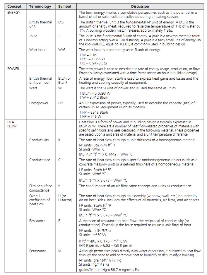
Table 1 Energy, Power, and Heat Terminology
FIG. 7 Heat flow through materials, across air spaces, and through construction
assemblies. Means of heat flow include conduction, convection, and radiation.
The System International (SI) equivalent is the number of watts that flow through 1 square meter (m^2) of material 1 m thick when the temperature difference across that material is 1 K (equal to 1ºC) under conditions of steady heat flow. Thus, the SI units of conductivity are W/m K or W/m ºC (these two terms are used interchangeably in the tables related to this Section).
Conductivity is established by laboratory tests and is published as a basic property of homogeneous solids. Conductivity is an important factor in passive heating or cooling designs that depend heavily upon the rate at which heat is conducted into a material from its surface.
Conductance. Many solids such as common brick, wood siding, batt or board insulation, gypsum board, and so on are widely available in standard thicknesses. For such common materials, it is useful to know the rate of heat flow for that standard thickness instead of the rate per inch. Conductance, designated as C, is the number of Btus per hour that flow through 1 ft 2 of a given thickness of material when the temperature difference is 1ºF. The units are Btu/h ft 2 ºF. SI units are W/m2 K. Conductance is also used to describe the rate of heat flow through defined sizes of modular units of nonhomogeneous materials (such as a concrete masonry unit- composed of pockets of air surrounded by concrete).
Resistance. Conductivity and conductance are compared in Table 1 and FIG. 8, which also include another useful property, resistance.
Designated as R, resistance indicates how effective any material is as an insulator. The reciprocal of conductivity (or conductance), R is measured in hours needed for 1 Btu to flow through 1 ft 2 of a given thickness of a material when the temperature difference is 1ºF. In the I-P system, the units are h ft^2 ºF/Btu. SI units are m^2 K/W. Resistances and other important thermal properties are listed for many conventional building materials in Table E.1 (Section E). Table E.2 provides similar information for alternative (less commonly used and/or emerging) construction approaches.
Resistance is especially useful when comparing insulating materials, because the greater the R-value, the more effective the insulator. For this purpose, R is sometimes listed as "per inch" of thickness, in which case the units are h ft 2 ºF/Btu-in. SI units are m K/W (indicating "per meter" of thickness across 1 m^2, even though the canceling units are odd).
FIG. 8 Relationship between conductivity, conductance, and resistance for
two typical materials. Glass fiber is a material of low conductivity (high
resistance); concrete is a material of high conductivity (low resistance).
Note: Standard unit of area is 1 ft 2 (1 m2); standard air temperature differential
is 1ºF (1ºC).
Emittance. Radiation heat transfer is highly influenced by surface characteristics; shiny materials are much less able to radiate than common rough building materials. This characteristic is called emittance, the ratio of the radiation emitted by a given material to that emitted by a blackbody at the same temperature. The impact of emittance (shiny vs. matte surfaces) is seen in Tables E.3, E.4, and E.5, which present properties of air layers and air spaces within construction assemblies; the lower the emittance, the lower the radiative heat exchange. For most materials, emittance is related to absorptance: a highly absorptive (low reflectance) material will usually have a high emittance as well. Selective surfaces (sometimes used in solar collectors) are highly absorptive yet have very low emittance.
(d) Thermal Classifications of Materials
Architectural materials generally interact with heat either as insulators that retard the flow of heat (useful for thermal barriers) or as conductors that encourage heat flow (useful for thermal storage materials). It is common to find both insulators and conductors in the same construction.
For example, a wall can have an inner layer that is highly conductive and thermally massive (for thermal storage), with an outer layer that is also highly conductive and thermally massive (for durability and weathering) and a highly insulative, low-mass material in between.
Insulations. Materials used for insulation fall into three broad categories: (1) inorganic fibrous or cellular products (such as glass, rock wool, slag wool, perlite, or vermiculite), (2) organic fibrous or cellular products (such as cotton, synthetic fibers, cork, foamed rubber, or polystyrene), and (3) metallic or metalized organic reflective membranes (which must face an air space to be effective).
Insulating materials are available in a wide variety of forms. Form-fitting materials include loose fill (as above a ceiling on the floor of an attic); insulating cement, a loose material mixed with a binder and troweled onto a surface; and formed-in-place materials such as expanded pellets or liquid-fiber mixtures that are poured, frothed, sprayed, or blown in place. Less form-fitting but more common are batts and blankets of flexible, semirigid insulation, with varying degrees of compressibility and adaptability to substrates.
Rigid insulation, with little on-site adaptability, is applied in blocks, boards, or sheets and can be preformed to fit non-planar surfaces such as pipes.
Exterior insulation and finish systems (EIFS) have become very popular (and controversial), both for retrofit and for new construction. Utilizing expanded polystyrene rigid boards applied to exterior gypsum, plywood, or cementitious substrates, then covered with fabric-reinforced acrylic, this construction method achieves slightly more than R-4 per inch of thickness (SI about R 28 per meter).
Reflective materials are available in sheets and rolls of either single or multiple layers, sometimes as preformed shapes with integral air spaces. When used without attachment to blanket or batt insulation, a reflective layer is called a radiant barrier and is especially applicable to roofs in warmer climates.
Radiant barriers are also useful in east- and west facing walls in such climates; details of applications in the southern United States are found in Melody .
A combination of dead (still) air spaces and reflective surfaces produces some of the most effective insulating products, especially when made of lightweight materials of low conductivity. Glass fiber, cellular glass, expanded styrenes (foamed plastics), and mineral fibers all enclose vast numbers of dead-air spaces per unit volume. When they are bonded to reflective films and properly installed (the shiny film facing a dead air space), high resistance to heat flow is achieved.
Conductors. Materials used as conductors are typically dense, durable, and able to diffuse heat readily. Table E.1 lists the density, conductivity or conductance, and specific heat for many common materials. For a given material, the higher the numerical values of these three characteristics, the more successful that material's performance as a conductor. Some specifics on thermal mass are presented in the following section and in Section 8.
Air Films and Air Spaces. Air films and spaces are interesting thermal components. Although they are actually void of material, they have potentially useful thermal properties and contribute substantially to the insulating capabilities of some construction assemblies. All aboveground envelope assemblies include at least two air films (interior and exterior), and many common assemblies include a substantial air space.
Air Films. At the exposed surfaces of solids, heat transfer takes place both by convection and by radiation. (Evaporation also can occur, occasionally with thermally significant results-see Fig. 8.44, the United Kingdom Pavilion, Seville, for an example of an entire wall used as an evaporative heat transfer element.) Convection is highly dependent upon air motion, so wind speed must be considered when estimating exterior surface convection. Also, because warm air rises and cold air falls, vertical surfaces that encourage surface air flow will exchange heat faster than similar surfaces placed horizontally, unless the direction of the heat flow is upward through the horizontal layer, as illustrated in FIG. 7.
When air motion along a surface is minimal, an insulating layer of air "attaches" itself to the surface. The resistance of this layer of still air along a vertical surface is equivalent to that of a thickness of ½-in. (12.7-mm) plywood. When this air layer is disturbed, however, its resistance drops quickly; with a 15-mph (6.7-m/s) wind, resistance drops to about one-quarter of the still-air value (see Table E.3). Similar drops in air film resistance occur when forced-air registers are located immediately above or below windows.
The insulation value provided by layers of air is often listed as conductance, the reciprocal of resistance. Surface conductances are designated hi for interior air layers and ho for exterior or out side air layers (sometimes the symbols fi and fo are used instead). Like other conductances, they are expressed in Btu/h ft 2 ºF (in SI units, W/m^2 K). The variations in surface resistances and conductances are shown in Table E.3.
Air Spaces. An air space is a planar volume of air contained on two sides by some elements (dry wall, brick, insulation, etc.) of an envelope assembly. Like the air films just discussed, air spaces can contribute to the overall thermal resistance of a construction assembly. As indicated in Tables E.4 (I-P) and E.5 (SI), the resistance provided by an air space is a function of its width, position (vertical, horizontal, tilted), and surrounding emittances.
To be effective in resisting heat flow, an air space must be relatively "dead"-without substantial air circulation.
(e) Composite Thermal Performance
The variety of terms used so far to express thermal properties is potentially bewildering. These properties are, however, only components of a larger picture. Fortunately, there is one overall property that expresses the steady-state rate at which heat flows through architectural envelope assemblies. This property is the U-factor.
U is the overall coefficient of thermal transmittance, expressed in terms of Btu/h ft^2 ºF (in SI units, W/m^2 K). U-factors are commonly used to specify envelope thermal design criteria, as presented in Section G and Section 8. Many codes and standards specify maximum U-factors (or, for insulation alone, minimum R- or maxi mum C-values) for various components of the envelope. An example of such requirements for a small office is found in EXAMPLE 7. Because U-factors are so important and so often encountered, data for typical wall, floor, roof, door, and window constructions are presented in many design resources.
U-factors are calculated for a particular element (roof, wall, etc.) by finding the resistance of each constituent part, including air films and air spaces, then adding these resistances to obtain a total resistance. The U-factor is the reciprocal of this sum (?) of resistances:
This procedure is shown in EXAMPLE 1. "Precalculated" U-factors for many common constructions are found in Tables E.6 through E.16, typically based upon an outside wind speed of 15 mph (6.7 m/s), except for summer conditions as noted.
Unfortunately, many common constructions are not so simple, as discussed in the sections that follow.
EXAMPLE 1 What is the winter U-factor for the wall assembly shown in FIG. 9?
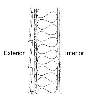
FIG. 9 Wall section used in EXAMPLE 1 to illustrate the pro cess for determining
a U-factor (overall thermal transmittance).
There are several important points to remember about the U-factor. The U-factor is a sensible heat property-addressing heat flow resulting from a temperature difference but not addressing latent (moisture-related) heat flow. The U-factor is an overall coefficient of heat transfer, and includes the effects of all elements in an assembly and all sensible modes of heat transfer (conduction, convection, and radiation). The term U-factor should be used only where heat flow is from air to air through an envelope assembly. Air to-ground heat flow (as through a slab-on-grade floor) is a different matter and is considered in Section 7.3(f).
Walls. Compared to other elements of the building envelope, wall U-factors are quite straightforward. There are few complications such as ground contact, crawl spaces (as with floors), or intermediary attic spaces (as with roofs). There is, however, the issue of thermal bridging: Where framing interrupts insulation, there are actually two different wall constructions, and an averaged (an insulated portion with an uninsulated portion)
U-factor must be found. EXAMPLE 2 illustrates this procedure.
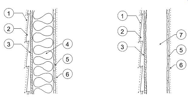
FIG. 10 Wall sections used in EXAMPLE 2 to illustrate the process for
determining a weighted-average U-factor to account for thermal bridging in
a frame wall.
EXAMPLE 2 Considering thermal bridging, what is the winter U-factor for the wall assembly shown in FIG. 10?
The effects of framing with wood studs are nominal but noticeable. With metal studs, the detrimental effects of thermal bridging are more serious; Table E.8 provides information on correction factors and resulting R-values. The latest editions of ANSI/ASHRAE/IESNA Standard 90.1, Energy Standard for Buildings Except Low-Rise Residential Buildings, and ANSI/ASHRAE Standard 90.2, Energy-Efficient Design of Low-Rise Residential Buildings, present examples of whole-wall U-factors that account for thermal bridging. See Section G for excerpts from Standard 90.1.
To illustrate the complexity of thermal bridging, consider the following range of U-factors, all for nominal 4-in. (100-mm) thick framed walls with R-13 [SI: R-2.3] insulation located within the stud cavity:
For the same type of wall construction (wood frame), increasing stud spacing from 16-in. o.c. to 24-in. o.c. (400 mm to 600 mm) decreases (improves) the U-factor from 0.094 to 0.091 (SI: 0.53 to 0.52)-a nominal difference. Changing from wood to steel studs (at 16-in. o.c.; 400 mm), however, increases (degrades) the U-factor from 0.094 to 0.134 (SI: 0.53 to 0.76)-equivalent to an R-3 (SI: R-0.5) decrease in insulation. If a detailed calculation of thermal bridging effects is required, consult the 2009 ASHRAE Handbook- Fundamentals, Section 25.
Several developments are promising to improve the thermal performance of wall systems. Structural insulated panels (SIPs) are now available in a wide variety of surfaces, insulation types, and thick nesses. Because a single factory-built panel replaces site-built framing, savings in labor can be substantial. Thermal performance is considerably improved because no framing members penetrate the insulated core. The typical SIP consists of two structural surfaces (often oriented-strand board, or OSB) that enclose a core of either expanded polystyrene (EPS) (R-4 per inch; SI: R-27.7 per meter) or polyisocyanurate foam (R-6.5 per inch; SI: R-45 per meter). The panels are joined with plywood splines that connect the structural surfaces of adjacent panels in a manner that reduces the thickness of, but does not interrupt, the insulated core. Another joining method, shiplap joints, maintains full-thickness core insulation. Air tightness is generally greater than with stud framing. U-factors of framed walls and SIPs are compared in Table E.9.
Insulated masonry systems can offer lower U factors while preserving a masonry exterior (for weathering and appearance) and a masonry interior (for thermal mass). Past approaches (filling hollow cores of concrete block or clay tile with insulation) left considerable thermal bridging through the solid masonry, with rather high resulting U-factors. If one of the masonry surfaces is not to be exposed, then a continuous layer of insulation can be applied to that face, with much lower resulting whole-wall U-factors. Even in cavity walls, the layer of insulation between wythes of block is usually penetrated by ties-with resulting thermal bridging. The most elementary improvement in this regard uses ties with lower thermal conductivity, such as fiber composite materials in place of steel. Another approach is to use precast blocks that can be stacked integrally with preformed rigid insulation; to the extent that the insulation layer can both be thick and unbroken by ties, thermal bridging is greatly reduced. The following is a sample of manufacturers' whole-wall U-factors for medium-density (120 lb/ft 3 [1920 kg/ m^3]) concrete block insulation alternatives:
8-in. two-core concrete block,
uninsulated U = 0.39 (SI: 200-mm two-core concrete block,
uninsulated U = 2.21) 8-in. two-core concrete block with
insulated cores U = 0.19 (SI: 200-mm two-core concrete block with insulated cores U = 1.08) 8-in. proprietary two-wythe concrete block and core U = 0.11 (SI: 200-mm proprietary two-wythe concrete block and core U = 0.62) Where poured-in-place concrete is not to be used as a surface material, insulating concrete forms (ICFs) can be used to improve thermal performance. This system employs preformed rigid insulation as a formwork for poured concrete; the form/insulation remains in place after the wall is poured. Rigid insulation thus protects both faces of the structural wall (although it isolates the thermal mass); exterior and interior finishes are then applied to the insulation.
Roofs. In the simple case of a roof/ceiling separating a conditioned space from the outdoors, the U-factor is calculated as for walls. Where insulation is broken by framing, the effects of thermal bridging must be considered. Table E.8 shows correction factors to be applied to insulation/metal truss assemblies. Similar adjustments, although of lesser magnitude, are required with wood framing. ANSI/ ASHRAE/IESNA Standard 90.1 presents several detailed tables of whole-roof U-factors that account for thermal bridging. If a detailed calculation of thermal bridging is required, consult the 2009 ASHRAE Handbook-Fundamentals, Section 25. Roof insulation, however, is often placed entirely above (or entirely below) the supporting structure, greatly reducing the effects of thermal bridging. There is a growing availability of above-the-roof-structure insulation materials, some penetrated by fastenings, others essentially unbroken. These options should be explored as a means of reducing roof heat loss and gain-with appropriate consideration of the environmental impacts of material selections.
Where an insulated ceiling separates a space from an uninsulated attic, the simplest approach is to assume that the attic is at outdoor temperature.
This assumption likely overestimates the winter heat flow rate because the temperature in a vented attic may be higher than the outdoor air temperature- but it simplifies analysis. If an accurate estimate of attic temperature is required, a more complex procedure is used, as presented in the 2009 ASHRAE Handbook-Fundamentals, Section 27. An attic is a space having an average distance of 1 ft (0.3 m) or more between the ceiling and the underside of the roof. A vented attic is often used to carry away moisture that may have migrated through the insulated ceiling. See Lstiburek and Carmody (1994) for detailed information on attic design practices.
Floors. When a floor is exposed to outdoor air (as with a cantilever or crawl space), the U-factor is calculated as for walls and roofs. When insulation is placed within framing cavities, the effects of thermal bridging must be included. It is becoming increasingly common to provide a continuous layer of insulation below the framing cavity, thus greatly reducing the detrimental effects of thermal bridging. ANSI/ASHRAE/IESNA Standard 90.1 presents several tables of whole-floor U-factors that account for thermal bridging.
Many codes require vented crawl spaces. In such situations, the simplest procedure is to insulate the floor above the crawl space and assume that the crawl space is at outdoor temperature.
This assumption overestimates the heat flow rate, because a vented crawl space will rarely be as cold (warm) as outdoor air under winter (summer) design conditions. If a more accurate analysis of crawl space design temperatures is required, or if crawl space walls are insulated, a more complex procedure is used, as presented in the 2009 ASHRAE Handbook-Fundamentals, Section 27. It is rarely energy-conserving, however, especially in colder climates, to insulate the walls of a crawl space instead of insulating the floor above. See Lstiburek and Carmody (1994) for detailed information on crawl space design practices.
Doors. Table E.10 lists U-factors for solid (no glazing) doors in common use in North America.
These precalculated values are convenient but should be used with care, as air film resistances are a relatively large factor in overall door thermal performance. Many doors are near forced-air sup ply registers or return grilles, reducing the resistance of the indoor air film. Conversely, the exterior air film may be more effective than anticipated because doors are typically protected somewhat by overhangs, porches, and so on. The wind conditions assumed in Table E.10 are typical of winter (not summer) conditions. Where significant door glazing is involved, U-factors for similar windows should be substituted or the specific manufacturer's product data used.
(f) Special Envelope Heat Flow Conditions
The overall coefficient of heat transfer (U-factor) is a convenient property for analysis of aboveground envelope assemblies. It is only applicable, however, to assemblies exposed to air on both the interior and exterior surfaces. In other situations, such as slab on-grade floors and belowground walls and floors, U-factor is not a well-defined property (how much soil is part of the floor?), and other thermal analysis methods must be used. Typically, data derived from empirical studies are used in lieu of fundamental heat flow equations. Because the concept of U factor is so simple to understand and apply, much of the empirical data are presented in terms of equivalent U-factors.
Slab-on-Grade Floors. Heat flow dynamics change when the lower surface of a floor is in direct contact with the ground. The ground is often at a temperature different from that of outdoor air, and earth is more conductive than air. Testing has shown that heat flow in this complex situation is strongly related to slab perimeter length. Table E.11 shows the heat flow rate through a concrete slab-on-grade, given as F2 units (per foot or meter of perimeter length) rather than U-factors (per unit area). Four edge insulation conditions are shown, with corresponding values of F2 for three climate zones. Interpolation can be used to estimate F2 for other climates (correlated to heating degree days). This procedure relates all heat loss from the floor to the length of perimeter.
Slab-on-grade heat loss illustrates the principle of diminishing returns: An incrementally higher R-value does not produce an equally lower heat flow. An insulation truism is that the first few inches (millimeters) of insulation make a much greater impact on the rate of heat flow than do the last few inches (millimeters). Table E.11 lists a maximum slab-edge R-value of 5.4 h ft^2 ºF/Btu (SI: R-0.95). If more slab-edge insulation seems desirable, consult Table E.12. Note how much more effective is vertical insulation at the exposed perimeter compared to insulation beneath the slab. The highest F2 value listed in Table E.12 is for insulation at R-10 (SI: R-1.8) not only around the perimeter, but also under the entire area of the floor slab. This lowest rate of heat flow is a reduction of just 25% from the performance provided by the same insulation employed only around the perimeter to a depth of 4 ft (1.2 m).
EXAMPLE 3 A warehouse will be built with a slab on-grade floor. The warehouse is 80 ft (24.4 m) square in plan. What is the relationship between total slab insulation and rate of heat flow through the slab?
Thus, a minimal initial investment of 640 ft 2 (60 m2) of 1-in. (25-mm)-thick insulation cuts the uninsulated slab heat flow by one-fifth. However, a vastly greater investment of 7040 ft 2 (654 m2) of 2-in. (50 mm)-thick insulation (22 times as much!) cuts the less-insulated heat flow only by one-fourth. ¦ Basements. Heat flow through basement walls and floors is complicated by an increasing length of the heat flow path with increasing depth, as shown in Figs. 7.11a and 7.11b. A further complication is that the temperature of the earth is not equal to ambient air temperature and becomes more and more out of phase with air temperature at increasing depths. To obtain a "design tempera ture" for belowground heat loss, first estimate the mean winter temperature of the site location. For example: using Tables C.19 and C.20 in Section C, take the average of the ambient temperature (TA) for January and for the year. Then, from this mean winter temperature, subtract the value of the constant amplitude, FIG. 11c. This gives a design temperature. Table E.13 is then used to determine the heat flow rate.
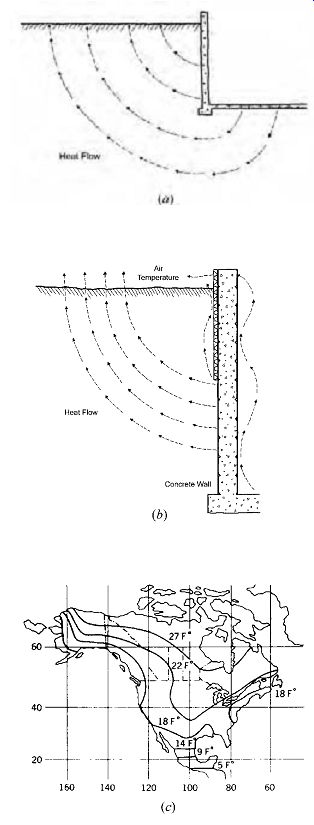
FIG. 11 Heat flow below grade. (a) Heat flow through basement walls and
floors follows radial paths (that are generally perpendicular to soil isotherms).
(b) Heat flow paths of differing lengths for a partially insulated basement
wall. (c) Lines of constant amplitude of ground temperature; just below the
surface, the ground temperature fluctuates around a mean annual temperature
by this amplitude (5ºF difference = 2.8ºC difference; 9ºF = 5ºC; 14ºF = 7.8ºC;
18ºF = 10ºC; 22ºF = 12.2ºC; 27ºF = 15ºC).
(g) Predicting Surface Temperatures and Condensation
Surface temperatures, as well as the temperature at any point within a wall, roof, or floor assembly, can be predicted if the inside and outside air temperatures and the thermal properties of the construction are known. The variance in temperature through a cross section of a construction assembly is called a thermal gradient. For any construction, the thermal gradient can be predicted by proportioning the collective thermal resistance at any point in the assembly to the overall difference in temperature across the assembly. This procedure is illustrated in EXAMPLE 5:
Understanding envelope surface temperatures is fundamental to predicting thermal comfort. How cold in winter, or hot in summer, will an interior surface be, and how will this affect mean radiant temperature? Understanding temperature patterns within materials is critical to establishing where water vapor might condense within or on a wall, roof, or floor assembly; this is discussed further in Section 7.9.
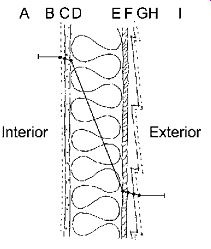
FIG. 12 Wall section used in EXAMPLE 5 to illustrate the procedure for
calculating a thermal gradient through a construction assembly.
(h) Dynamic Thermal Effects
The preceding discussion of thermal properties of materials and assemblies focused upon static (steady-state) conditions. Such conditions are usually presumed for analysis of winter heat loss (assumed to occur under the darkness of night). A more complex situation exists when thermal conditions experience rapid changes-such as those brought about by solar radiation impinging upon various portions of the building envelope. Dynamic conditions are usually presumed for analysis of summer heat gain (assumed to occur during day light hours). The dynamic situation requires consideration of more thermal properties.
Under static conditions, heat flow is primarily a function of temperature difference (the driving force) and thermal resistance (the resisting force). Under dynamic conditions, these two factors are still important, but heat storage in the envelope assembly itself becomes a compounding issue. Heat storage is a function of the density of a material and its specific heat; the product of these two properties is known as thermal capacity. Thermal capacity can (but will not always) reduce heat flow via storage. Heat entering a wall construction during the daytime, for example, can be stored within the wall for several hours until it flows back out to the cool night air-assuming appropriate weather conditions and adequate thermal capacity. As a minimum, the effect of heat entering a massive wall at, say, 10:00 A.M. will not be seen on the interior surface until a few hours later.
Density. Density is the weight of a material per unit volume. In the I-P system, density is given as lb/ft 3; in the SI system, it is given as kg/m3. For a fixed volume of material, greater density will permit the storage of more heat. Table E.1 provides density data for common building materials.
Specific Heat. Specific heat is a measure of the amount of heat required to raise the temperature of a given mass of material by 1º. In the I-P system, this is expressed as Btu/lb ºF; in the SI system, it is expressed as kJ/kg K. It takes less energy input to raise the temperature of a low-specific-heat material than that of a high-specific-heat material. Table E.1 provides values of specific heat for common building materials.
Thermal Capacity. Thermal capacity is an indicator of the ability of a fixed volume of material to store heat. The greater the thermal capacity of a material, the more heat it can store in a given volume per degree of temperature increase. Thermal capacity for a material is obtained by taking the product of density and specific heat; for example:
Thermal capacity for concrete: (140 lb/ft^3) (0.24 Btu/lb ºF) = 33.6 Btu/ft^3 ºF SI: (2240 kg/m^3) (1.0 kJ/kg K) = 2240 kJ/m^3 K Thermal capacity for water: (62 lb/ft^3) (1.00 Btu/lb ºF) = 62.0 Btu/ft^3 ºF SI: (992 kg/m^3) (4.18 kJ/kg K) = 4147 kJ/m^3 K Thermal capacity for air: (0.075 lb/ft^3) (0.24 Btu/lb ºF) = 0.02 Btu/ft 3 ºF SI: (1.2 kg/m^3) (1.0 kJ/kg K) = 1.2 kJ/m^3 K
Time Lag. Time lag is a measure of the delay in the flow of a pulse of heat through a material that results from thermal capacity. Units are hours.
As an example, if the sun comes out from behind clouds and strikes the exterior surface of a mass wall at 10:00 A.M., the exterior surface temperature will rise quickly. It may be several hours, however, before this temperature "spike" is seen at the inside surface of the wall. The reason is that some heat is being stored in the wall material, and that heat will not continue to flow through the wall. Time lags of several hours are possible with very heavy wall constructions.
The design effects of capacitive insulation are difficult to analyze without computer assistance. As a result, most hand calculation methods incorporate capacitive effects through the use of surrogate variables that attempt to simplify calculations for the end user.
4. LATENT HEAT FLOW THROUGH THE OPAQUE ENVELOPE
The information presented in Section 7.3 focused upon sensible heat flow through various elements of the building envelope. Water also moves through building envelope assemblies-in both liquid and vapor states. The focus here is upon water vapor movement (assuming that proper architectural design of the envelope components will control the movement of liquid water). Water vapor will often need to be handled by a climate control system through the use of energy (termed latent heat). In the summer, moisture will typically flow into an air-conditioned building, increasing humidity and requiring dehumidification, which is often accomplished through removal of the latent heat of condensation of the added moisture. In the winter, it is not unusual to add water vapor to the air in a building to keep RH from dropping too low.
This is often accomplished by evaporating water by adding the latent heat of vaporization. In some building types and climates, dealing with latent heat may be as big a problem as dealing with sensible heat.
(a) Moisture Control Fundamentals
A difference in vapor pressure is the driving force behind moisture flow through components of an intact building envelope assembly, while gaps in the envelope can provide a route for airflow that carries water vapor. Vapor pressure difference is to latent heat flow as temperature difference is to sensible heat flow. The permeance of the materials of construction is the latent equivalent of sensible conductance. (As with conductance, permeance refers to the bulk properties of a material, and permeability refers to unit thickness properties.) The less permeable a material is, the greater the resistance to water vapor flow. Materials with low permeance are termed vapor retarders, and are incorporated in envelope constructions as a means of reducing the flow of water vapor and subsequently the risk of condensation of the vapor within the envelope assembly. I-P units of permeance are grains/h ft 2 in. Hg; SI units are ng/s m^2 Pa. (Grains refers to grains of water, with 7000 grains per pound; in. Hg is inches of mercury, a pressure measurement; ng is a nanogram or 10^-9 of a gram.) The I-P units for vapor pressure are in Hg; the SI units are Pa [pascals].
From an architectural design perspective, reducing water vapor flow is accomplished using very thin materials (membranes) that must be carefully located to ensure that they work as intended. Although placement within an envelope assembly is critical, vapor retarders take up virtually no space-in drastic contrast to the thickness requirements of sensible heat retarders (insulations). The specific location of a vapor retarder within a wall, roof, or floor cross section will vary with climate and construction types. The fundamental principle, however, is for the retarder to stop the flow of water vapor before the vapor can come in contact with its dew point temperature within the assembly.
(b) Cold Climate Moisture Control
Most common building materials, including gyp sum board, concrete, brick, wood, and glass fiber insulation, are easily permeated by moisture.
Most surface/finish materials are also permeable.
In cold climates, the winter outside air contains relatively little moisture, even though the RH may be high. By contrast, inside air contains much more moisture per unit of volume, despite its probably lower RH. The resulting differential vapor pressure drives the flow of water vapor from high to low vapor pressure (typically from warm to cold).
The primary problem with water vapor flow in winter occurs when the temperature somewhere within a wall, floor, or roof drops low enough for water vapor passing through the assembly to con dense. The temperature at which this occurs is the dew point temperature of the air acting as the source for the water vapor. Such a temperature often occurs within the insulation layer. Insulation can then become wet and thereby less effective, because water conducts heat far better than the air pockets it has filled. If wet insulation compacts, the air pockets are then permanently lost. Worse yet, moisture damage can occur, such as dry rot in wood structural members.
The usual remedy for envelope condensation problems in cold climates is a vapor retarder installed within the building envelope assembly.
Because very low permeability is desired, these retarders are commonly a plastic film installed with as few gaps and holes as possible. Because the moister air on the warm side of the envelope is the source of the problem, the vapor retarder needs to be installed as close to the warm side as possible- typically, just behind the interior surface (gypsum board, wood flooring, etc.) before the dew point can be encountered. However, with higher insulation R-values, it is becoming common to install the vapor retarder within the insulation at a point about one-third of the distance from the interior to the exterior. This allows the inner one-third of the wall to be used as a chase for wiring or plumbing without penetrating the retarder, yet with enough insulation beyond this point to prevent condensation by maintaining the temperature above the dew point.
Another approach is to use vinyl wallpaper or vapor retarder paints on interior surfaces of the envelope. These give less protection, how ever, than the around-the-corners wrap that can be achieved with properly installed plastic films. This performance disadvantage is shared by aluminum foil-faced insulation; it is very effective thermally but less effective as a vapor retarder. Also, the aluminum foil must face an air space if it is to be thermally effective as a radiant barrier.
A substantial benefit of plastic films is that they also reduce airflow through construction-acting as an air barrier. Outdoor air is always infiltrating a building, gradually replacing the indoor air.
This unintended flow of cold air becomes a problem when temperatures outside are very different from those inside, especially when strong winds force outdoor air indoors fast enough to produce notice ably cold drafts. Therefore, the combined moisture--and infiltration-tight characteristics of plastic film vapor retarders are usually beneficial.
In cold climates, condensation on cold interior surfaces can also occur, especially at windows (with little resistance to reduce the slope of the thermal gradient). Occupant annoyance or material dam age can result. Although the air indoors may not be particularly humid (perhaps 30% to 50% RH), it often contains enough moisture to support condensation on cold surfaces. Condensation can be readily predicted (see FIG. 12) and addressed during design.
(c) Hot, Humid Climate Moisture Control
In hot, humid conditions, cool inside surfaces are often encountered-for example, a radiant cooling panel containing chilled water, a water pipe, or a supply air diffuser. If hot, humid air contacts such a surface, condensation can occur, with the moisture vapor in the air condensing to form visible droplets of water on the cool surface. The result can be mildly annoying if droplets of condensation fall on occupants, or serious if water stains occur and, eventually, mold grows on damp surfaces.
In hot, humid climates, the object is to keep the moisture in the warmer outside air from penetrating to the cooler (and usually less humid)
interior. One method is to use a drainage plane, installed just inside the exterior surface material, to block the flow of liquid water through the envelope. The drainage plane can consist of simple tar paper (building felt). If any moisture succeeds in penetrating this drainage plane, it should be allowed to wick to the interior; therefore, no vapor retarder such as plastic, vinyl wallpaper, or vapor retarder paints should be used on interior surfaces. Numerous severe problems with water vapor damage to building interiors-and related mold and mildew growth, with associated IAQ problems-have recently been publicized, typically related to condensation of moisture on the exterior-facing (hidden) side of vinyl wall coverings used as an interior finish. See Lstibuek and Carmody (1994) for details on hot and cold climate moisture control.
5. HEAT FLOW THROUGH TRANSPARENT/TRANSLUCENT ELEMENTS
Heat flow through windows and skylights re quires special attention for several reasons. Despite dramatic improvements, these transparent/trans lucent envelope components still usually have the lowest R (highest U) of all components of an envelope. Also, they are major contributors to infiltration of outdoor air, which adds to winter heating or summer cooling loads. Perhaps thermally most important, they admit solar heat, for better (winter) or worse (summer). By design, this radiation (heat) passes through a window or skylight with minimal resistance, which complicates thermal analysis. Transparent/translucent devices also admit daylight to buildings and often provide desired ventilation. The huge variety of such components and the several important roles they play require special attention from designers.
A standardized approach to rating window performance characteristics has been developed.
This approach is coordinated by the National Fenestration Rating Council (NFRC). Each window or skylight manufactured in the United States bears an NFRC label certifying that the window has been independently rated. The label carries a brief description of the product, such as "Model #, Casement, Low-e = 0.2, 0.5" gap, Argon Filled" and lists the following mandatory information: U-factor, solar heat gain coefficient (SHGC), and visible light transmittance (VT). FIG. 13 shows a sample NFRC label. Similar labels are available for site-assembled window units. Characteristics of some residential-sized windows are found in Table E.15.
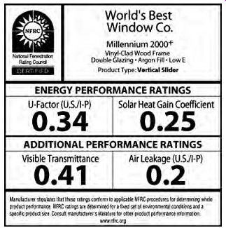
FIG. 13 Certifying window
thermal performance; a sample NFRC window label. Air leakage and condensation
resistance data are optional. (National Fenestration Rating Council)
The following sections provide information on fundamental thermal properties of transparent/ translucent assemblies and approaches that can be taken to enhance the performance of such assemblies. A transparent material permits a generally undistorted view (as with clear glass); a translucent material permits at best a distorted view (as with glass blocks or milky plastic). Both types of material, however, permit some unimpeded transmission of radiation-as opposed to an opaque material/ assembly that permits no direct solar radiation transfer.
(a) U-factor
As with opaque envelope components, heat flow due to temperature differences through windows and skylights is a function of the U-factor. The determination of U-factors for windows and sky lights is complicated by significant differences in heat flow rates between the center-of-glass, edge of-glass, and frame portions of a unit. The NFRC "U-factor" melds these into a single representative value for an entire window or skylight unit. The size of the air gap between glazings, the coatings on the glazings, the gas fill between glazings, and the frame construction all influence the U-factor.
The lower the U-factor, the lower the heat flow for a given temperature difference. Tables E.14, E.15, and E.16 list U-factors for various windows and skylights. Section G presents sample requirements for window U-factors and SHGC (solar heat gain coefficient, see Section 7.5b) for nonresidential buildings excerpted from ANSI/ASHRAE/IESNA Standard 90.1-2007.
(b) Solar Heat Gain Coefficient (SHGC)
This thermal property is also generally based upon the performance of the entire glazing unit, not just that of the glass portion. SHGC represents the percentage of solar radiation (across the spectrum) incident upon a given window or skylight assembly that ends up in a building as heat. It is a measure of the ability of a window to resist heat gain from solar radiation. SHGC can theoretically range from 0 to 1, with 1 representing no resistance and 0 representing total resistance. SHGC values for real products typically range from about 0.9 to 0.2. SHGC is dimensionless. A high SHGC (meaning poor resistance to radiant gain) is desirable for solar heating applications, whereas a lower SHGC (good resistance) is better for windows where cooling is the dominant thermal issue. The SHGC depends upon the type of glass and the number of panes, as well as tinting, reflective coatings, and shading by the window or skylight frame.
NFRC tests and lists SHGC values only for glazing units; laboratory testing does not include auxiliary elements such as draperies, overhangs, trees, and the like. Prior to the development of the SHGC approach, the term shading coefficient (SC) was universally used to quantify the same concept. Shading coefficients, however, were based only upon the glass portion of a glazing unit-specifically excluding the frame. Although theoretical SC values also range from 0 to 1, the basis of SC is different from that of SHGC. SC is the ratio of radiant heat gain through a given type of glass relative to 18-in. (3-mm)-thick single clear glass. SC is still a useful concept for comparing glass types and especially for expressing the effects of external or internal shading devices.
A wide variety of window and skylight U factor, SHGC, and VT (see Section 7.5c) data can be found in Section 15 of the 2009 ASHRAE Handbook-Fundamentals. Tables E.17 through E.24 list SHGC, SC, and/or VT values for various types of transparent/translucent products and shading approaches.
A small sample of U-factors for skylights is shown in Table E.16. Note in this table the great thermal penalty paid when using smaller units: the "manufactured skylights" are 2 ft × 4 ft (600 mm × 1200 mm), whereas the "site-assembled glazing" unit size is 4 ft (1200 mm) square. For otherwise identical construction, the whole component U-factors are almost twice as high for the smaller units. With these smaller units, a frame with better thermal performance is a smart investment.
(c) Visible Transmittance (VT)
This thermal/optical property represents the percentage of incident light (only the visible spectrum) at a normal angle of incidence that passes through a particular glazing. VT is dimensionless.
The higher the visible transmittance, the greater the daylight transmission. VT is influenced by the color of the glass (clear glass has the highest VT) as well as by coatings and the number of glazings.
VT may be expressed relative to the glass portion only of a glazing unit or relative to the glass and frame. The appropriate expression will depend upon the nature of an analysis; in any case, non-comparable values should not be compared.
All NFRC-certified VT values should be directly comparable.
It might seem intuitive that any glazing or coating that reduces SHGC (via lower radiation transmission) will also reduce VT (implying lower radiation transmission). This is not always the case, however, as SHGC deals with the full solar radiation spectrum (including light), whereas VT deals only with the visible (light) spectrum. Spectrally selective glazings and selective coatings are available that greatly reduce SHGC with little reduction in VT. The relation ship between SHGC and VT is expressed as the light-to-solar gain ratio (LSG) obtained by dividing the VT by the SHGC. The greater the LSG, the more suitable a glazing is for daylighting in hot climates (or wherever cooling is the dominant thermal condition). Values of LSG are not listed on NFRC labels. LSG values for common glazing units (including the effects of the frame) are included in Table E.15.
(d) Air Leakage
This is the rate of outdoor air infiltration between a new window and its frame measured under defined conditions-usually under pressure equivalent to that of a 25-mph (40-km/h) wind, with the window locked. High-performance windows may be tested/rated at even higher pressures. As weather stripping deteriorates with age, higher rates of infiltration may be expected with older and well-used windows. Design air leakage values are not required to be listed on NFRC labels but may be obtained from manufacturers' catalog data.
(e) Low-Emittance (low-e) Coatings
These coatings are typically applied to one glass surface facing into the air gap between multiple glazings. A low-e coating blocks a great deal of the radiant transfer between the glazing panes, reducing the overall flow of heat through the window and thus improving the U-factor. Indeed, one such coating is almost as effective as adding another layer of glazing. In Table E.15, compare the U-factor for window 5 with the U-factors for windows 7 and 12. An important added benefit of these films is their reduction of UV transmission, thus reducing fading of objects and surface finishes in rooms.
Two approaches to providing low-e films are hard-coat (durable, less expensive, but less thermally effective) and soft-coat (better thermal performance but more expensive and subject to degradation by oxidation in the manufacturing stage).
Three common types of low-e coatings are:
1. High-transmission low-e:
For passive solar heating applications, where a low U-factor is combined with a high SHGC; window 7 in Table E.15 is an example. The coating is on the inner glazing, where it traps outgoing infrared radiation that otherwise would be lost. Summer overheating can be avoided with external shading devices.
2. Selective-transmission low-e:
Where winter heating and summer cooling are both important, requiring low U-factor and low SHGC, but with a relatively high VT for daylighting. Window 9 in Table E.15 is an example, with an LSG ratio of 1.65. The coating is on the outer glazing, where it blocks incoming infrared radiation, which as heat is then convected away by outdoor air.
3. Low-transmission low-e:
Where the sun is the enemy, low U-factor, low SHGC, and even low VT seem warranted. Window 10 in Table E.15 is an example, again with the coating on the outer glazing, where it rejects more of the solar gain. With a tinted exterior glazing, even lower SHGC and VT could result.
(f) Selective Transmission Films
Heat flow due to radiation can be greatly reduced by the introduction of selective transmitter (or low-emittance) film somewhere within the glazing cavity. As shown in FIG. 14, these films admit most of the incoming solar radiation in both the visible and near-infrared (short) wavelengths. Warm objects within a room emit far-infrared (long-wave) radiation. This long-wave radiation is reflected back into the room by the selective film. These selective films typically are available as separate sheets that can be inserted between sheets of glazing as a window is fabricated. As a separate sheet, a selective film could also be applied to existing windows-for instance, between storm windows and the ordinary windows they protect.
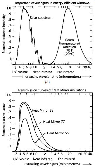
FIG. 14 Performance of
selective transmitters. (a) Spectral characteristics of solar (short-wavelength)
radiation and room temperature (long-wavelength) radiation. (b) Transmission
and reflection performance for several Heat Mirror selective transmitter films.
Incoming solar radiation (both visible and near-infrared) is mostly transmitted,
whereas heat radiated from room temperature objects is reflected and thereby
kept within heated spaces.
With continuing advances in glazing performance, an increasing range of selective transmission options is available. For example, products from Southwall Technologies range from Heat Mirror 77 (low reflectance, recommended for vertical glass) to Heat Mirror 22 (low transmission, recommended for sloping glass), and provide various colors. A clear Heat Mirror 88 has the lowest reflectance of all. Some skylight and greenhouse manufacturers offer this low-emittance product as a standard option.
(g) Inert Gas in the Air Gap
Filling an enclosed air space with argon or krypton has thermal benefits. These less-conductive gases greatly reduce heat transfer by convective currents within the air gap between multiple glazings, producing lower U-factors. As a result, the inner surface of the glass is maintained at a temperature closer to that of the indoors, with greater comfort (because radiant heat flow to or from the window surface is reduced) and less chance of condensation on the inside surface. To preserve this gas fill over the life of the window, a very reliable edge seal is required.
For argon, the optimum air gap width is about ½ in. (12 mm). When a thinner window is needed, more expensive krypton can be used with an air gap of only ¼ in. (6 mm). Because the combination of inert gas and low-e coatings is so effective at lowering the U-factor, most manufacturers offer them together (as with windows 7 through 11 in Table E.15) rather than separately.
(h) Superwindows
When all of the currently available high-performance glazing options are combined in one product, it is called a superwindow. The combination of multiple glazings and/or suspended films, coatings, inert gas fill, and sealed/thermally broken frame construction yields a lower heat flow rate and a higher price.
Window 11 in Table E.15 is a superwindow. An early example of a superwindow, a double-glazed assembly with two selective films, yielding three gas-filled cavities, is shown in FIG. 15. With a combination of superior thermal resistance and useful solar gain potential, superwindows can conceivably provide better heating-season thermal performance than an insulated opaque wall. The potential design consequences are enormous. FIG. 16 compares the heating- and cooling-season performance, in a residential application, of several windows in three locations in the United States with quite different climates.
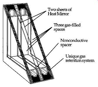
FIG. 15 The Superglass window system (an early superwindow) utilized two Heat
Mirror films between two outer panes of glass.
Three air spaces are thus created and filled with a nonreactive gas mixture to retard convection. Nonmetallic spacers reduce heat flow at window edges. The resulting window provided a center-of-glass insulating value of R-8.1 (SI: R-1.43). (ASHRAE lists for a similar window, non-operable, 4 ft (1220 mm) square, an overall window U = 0.19.) Very low transmission of UV radiation is another characteristic.
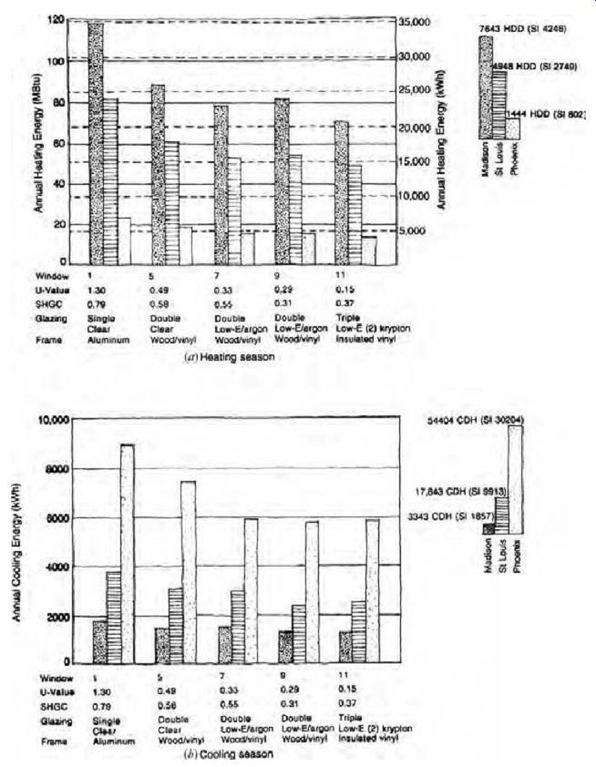
FIG. 16 (a, b) Seasonal energy performance comparison of various windows-assuming
a typical 1540-ft 2 (143-m^2) residence with a glazing area of 15% of the floor
area, equal glazing area on all four orientations, and no external or internal
shading. Window numbers correspond to those in Table E.15. MBtu = millions
of Btu; HDD = heating degree days, base 65ºF (18.3ºC); CDH = cooling degree
hours, base 74ºF (23.3ºC). U-factors in figure are I-P values; multiply these
by 5.678 for SI U-factors.
(i) Shading
Perhaps the single most important energy-related component for passively cooled buildings is the sunshade. Because many solar-heated buildings will experience overheating in hot weather, sun shading is critical for passively heated buildings as well. If correctly implemented, sunshading rejects most solar heat gains yet aids in distributing day light deep into buildings, where it reduces internal heat gains due to electric lights.
If a building is arranged to intercept the intense rays of the sun before they pass through its trans parent envelope elements, instead of afterward, the cooling load can often be cut in half. In approximate terms, effective external shading rejects about 80% of the fierce attack of solar energy, whereas internal shading absorbs and reradiates 80% of it.
Outside louvers have a chance to cool off in an occasional breeze, but inside draperies are part of a heat trap, and they constitute a system of hot-weather radiant heating that causes discomfort for those who work near perimeter surfaces.
To properly reject direct sun yet allow for a view and daylight, many sunshades project out from the windows they protect. These exterior projections become highly visible elements of façades, and they tempt some designers to impose formal aesthetic criteria that can be damaging to the solar control functions. A frequent example is the application of the same sunshade geometry to all façades of a building.
When the sunshades are fixed in position, this tends to help one façade but not the others. Where they are movable, as with awnings, this same-sunshade effect is not so serious.
Fixed sunshading devices are very common, partly because they lack moving parts and controls that can be expensive and troublesome. They pose a dilemma in the spring and fall, however, because in order to block the sun on any elevation in September, they will also block it in March. For many buildings in temperate climates, March is a heating-need month, whereas September is a cooling-need month. A procedure for evaluating fixed shading device performance is presented in Section 6; some approximate shading effects, expressed as shading coefficients, are found in Tables E.20 and E.21.
Adjustable sunshading, once extremely common (it seemed as if every 1930s shop and office window had an awning) but later considered old fashioned, has made a comeback with the increased interest in passive cooling. Some basic approaches to adjustable shading devices are shown in Table E.22. The first type shown, made of durable materials, has proved effective against both break-ins and hurricanes.
How are movable shading devices adjusted to the desired position? Most manufacturers offer three types of controls: manual, motorized, and automatic.
Manual systems are cheap and relatively trouble free, but they require thoughtful, timely action by the users of a building. So do motorized controls, but for adjusting large/heavy devices in remote places (clerestories, for example), motorized assistance is a practical necessity. Automatic systems have the advantages of freeing the users from adjustment tasks and of taking into account the thermal needs of the building as a whole when setting the sun shade's position. With computerized controls becoming commonplace for large buildings, the added costs of controls for automatic sunshading can easily be incorporated into the overall cost of controls.
Interior shading devices are less effective than exterior devices but are far more commonly used.
There are several reasons for this seeming contra diction. They are not subject to weathering or dirt accumulation and generally are easier for users to adjust. The designer who prefers a clean, apparently unchanging façade appearance will rely on interior devices. Tables E.23 and E.24 list shading coefficients for several combinations of interior shading devices.
The overall performance of multiple shading devices/approaches can be estimated by taking the product of the shading coefficients for individual devices that are used in series. For example, the overall shading coefficient of a window with external shading with an SC of 0.75, integral shading from the glazing unit of 0.65, and internal shading providing an SC of 0.7 is (0.75) (0.65) (0.7) = 0.34.
In general, shading coefficients lower than 0.2 should be used with caution. There is no direct conversion between SHGC values and SC. Nevertheless, it may be necessary to convert an SHGC value to SC in order to determine the overall shading performance of a glazing unit with external or internal shading devices. In this case, an approximate conversion of SC = SHGC/0.87 may be used.
6. TRENDS IN ENVELOPE THERMAL PERFORMANCE
As a result of the oil embargo of the early 1970s, there have been huge increases in installed component R (therefore, huge decreases in assembly U-factor) over the past 30-plus years. Sometimes this has occurred because of the use of increased thicknesses of insulation (as with many current wall and roof designs), sometimes because of substantially changed materials (as with windows). Improvements in code minimum values for envelope performance at times seem painfully slow to emerge, especially in light of growing concern for global warming mitigation and green design initiatives. Then again, publication of the Advanced Energy Design Guide series (ASHRAE) has been a welcome addition to the designer's tool kit. Although not mandatory, these guides suggest easy-to-adopt ways to reduce building energy consumption- including improvements in envelope performance.
What might the next quarter-century bring, and how might the designer of today's building envelopes anticipate-or participate in-these advances? Structural systems may be changing due to the advent of SIP. They promise greatly improved insulation and airtightness compared to the site assembled wood or steel framing systems they would replace. SIP can incorporate the latest developments in both insulated cores and thermal storage surfaces, and do so with less thickness and lighter weight than stick-built alternatives. Since the early 1970s, walls have progressed from using R-7 (SI: R 1.23) batts between typical 2-in. × 4-in. (50-mm × 100-mm) studs to R-26 (SI: R-4.58) batts between 2-in. × 6-in. (50-mm × 150-mm) studs plus insulating sheathing, thereby providing a threefold reduction in heat flow. With insulated cores for SIP now approaching R-25 and higher (SI: R-173), the next quarter-century could produce yet another three fold reduction in heat flow without an increase in wall thickness. Another potential development is an interior panel surface of phase-change wallboard, to store and release heat at room temperatures. This could increase thermal capacity considerably with very little increase in weight, with advantages for winter solar heating and summer night ventilation.
Floors and roofs can similarly benefit from the use of SIP rather than framed construction.
Insulation developments include aerogel, gas filled panels, powder-evacuated panels, and com pact vacuum. Some of these products are suitable for retrofit applications in existing construction.
Aerogel is both transparent and porous, one of the lightest solid materials. Silica aerogel can be foamed into cavities without ozone-depleting CFCs. In a 90% vacuum, silica aerogel has a resistance of R-20 per inch (SI: R-139 per meter). By adding carbon to absorb infrared radiation, R-32 per inch (SI: R-222 per meter) is possible.
Gas-filled panels are hermetically sealed plastic bags enclosing honeycomb baffles of thin polymer films and low-conductivity gas (argon, krypton, or xenon). Relative resistance values of these insulating cores are: argon, R-5.2 per inch; krypton, R-13.4 per inch; and xenon, R-19.3 per inch (SI: R-36, 93, and 134 per meter, respectively). Powder evacuated panels contain a vacuum and compacted silica-based powder sealed within a multilayer gas barrier. Expensive to produce and threatened by punctures, this may be a development more suited for appliances than for buildings. The resistance is about R-20 to R-25 per inch (SI: R-139 to R-173 per meter).
Windows have undergone the most dramatic thermal improvement. Resistances for window units (glazing plus frame) have evolved from about R-1 (SI: R-0.18) to R-6.5 (SI: R-1.14) or more.
Prototypes as high as R-20 (SI: R-3.52) exist. This improvement has been accomplished through a series of developments: a second layer of glass; a wider air space between glazing layers; tinted, reflective, photochromic, and low-emissivity coatings; low-conductivity gas between glazings; inter mediate films between glazings; operable blinds between glazings; lower-conductivity glazing spacers and frames; and more airtight weather stripping (to reduce infiltration). Future developments are likely to include smart windows with on-demand variable light transmission. For example, in electro chromic glazing, an applied electric field switches the window from a clear state to one with a deep coloration; intermediate states of coloration are possible. The most likely application is in cooling dominated climates where control of glare, solar gain, and visual privacy are paramount. Carmody et al. (1996) provide an excellent overview of residential window technologies, while Carmody et al. (2003) provide a similar overview of commercial window technologies.
Before the oil embargo of the early 1970s, windows represented the component with the greatest heat flow rate in a typical building envelope. Today, the highest rate of heat flow is more likely to be from outside air infiltration (or deliberate ventilation). Windows do so many things in addition to providing weather protection-admitting daylight, allowing views outdoors and in, admitting breezes, and admitting warming winter sun-that their relative thermal weakness compared to their desirability continues to challenge manufacturers. Over the next quarter-century, windows may well continue to display the most dramatically improved resistance to heat flow of all the components of the envelope.
Roofs are of particular interest relative to heat gains and losses because they are subjected to such extremes. On a clear night, radiant losses to the sky can lower a roof's surface temperature below that of the outdoor air-beneficial in summer, but a problem in winter. In summer, elevated roof surface temperatures in sunlight are dramatic and problematic. Efforts are under way to disseminate information regarding the benefits of cool roofs and to incorporate credit for such roofs into national energy codes. Both reflective roofs and green (or eco-roof) designs are being employed.
As discussed in Section 7.7, limiting heat flow via unwanted air movement is an important aspect of envelope design. The tightness of buildings has improved remarkably over the past 20 years, partly due to improved components (such as windows) and partly due to increased care in construction (involving caulking and air barriers/retarders). As a result of this improvement, building airtightness as a means of reducing energy usage is now in conflict with IAQ needs and concerns. It is likely that future improvements in this area will revolve around the use of heat recovery ventilators that permit reasonable ventilation rates without excess energy penalties.
Commissioning of the building envelope is an emerging trend. Commissioning goes beyond construction quality control to attempt to ensure (through design review, documentation, and testing) that envelope design, construction, and maintenance meet the owner's project requirements.
The National Institute of Building Sciences developed a building envelope commissioning guideline that is available via the Whole Building Design Guide (NIBS).
7. HEAT FLOW VIA AIR MOVEMENT
Outdoor air can enter a building by means of infiltration and/or ventilation. Infiltration is an unintended influx of outdoor air due to air leakage through the building skin. Ventilation is a deliberate, designed introduction of outdoor air. In either case, air at a different temperature and humidity interacts with the air inside a building. This inter action brings sensible and latent heat loads. Of the two means of air entry, infiltration is the more difficult to predict, since it is by definition unintended.
Ventilation air quantities are intended and thus easily quantified. Although it is possible for infiltration and ventilation to occur simultaneously, usually it is reasonable to assume one of the following scenarios: only infiltration (which is typical of many smaller buildings with no ventilation) or only ventilation (typically required by code for larger buildings, and which usually pressurizes a building and blocks infiltration). Both infiltration and ventilation airflow rates are expressed in cubic feet per minute (cfm); in SI, the units are liters per second (L/s).
(a) Infiltration
The main problem with infiltration is estimating how much air will leak into a building once it is built. There are two primary means of calculating the infiltration airflow rate during design: the air change method and the crack method.
The air-change method is very simple and quick but tends to overestimate. Air-change is a correlation method wherein observed performance of a set of existing buildings is matched (correlated) to key characteristics of a proposed building. The characteristics used are construction type and climate.
Virtually no detailed information about a building or its spatial arrangement is required. Table E.27 lists estimated numbers of air changes per hour (ACH) as a function of these two characteristics.
ACH is indicative of the "turnover" of air within a building or space. The greater the ACH, the greater the rate of outdoor airflow. A tight building might permit 0.25 ACH or so, a leaky building 1.0 ACH. ACH can be converted to airflow rate as follows:
V =
(ACH)(volume, ft ) 60min /h 3 where V is airflow rate in cfm.
In SI units:
V =
(ACH) (volume, m ) 3600 sec /h^3 where V is in m^3/s.
Although both m3/s and L/s are used as SI units of airflow rate, L/s is more commonly encountered in building design work. L/s = m^3/s × 1000.
The crack method requires more effort and assumes that data on window and door construction and wind velocities are known. It also assumes that all infiltration under design conditions is due to cracks around doors and windows. To estimate the airflow rate, calculate the length of cracks on the windward exposure(s) only and multiply this by the respective assembly air leakage rate(s) as follows:
V = (total lin. ft of window/door edge)
× (air leakage rate(s), cfm per lin. ft)
where V is in cfm.
In SI units:
V = (total lin. m of window/door edge)
× (air leakage rate(s), L/s per lin. m) where V is in L/s.
See Table E.15 for generic air leakage data or get NFRC or manufacturer's ratings for a specific product. If air leakage rates are unknown, Table E.28 shows how much leakage per unit length of crack should be assumed, for the windward exposure(s) only, to arrive at the total infiltration airflow rate.
Multiply the total length of crack by the infiltration rate from part B of Table E.28.
It is possible to measure the actual infiltration performance of a constructed building using a fairly simple device called a blower door. Some energy codes require that building tightness be verified by a blower door test. As a result, local utility companies may be able to provide reasonably accurate values for air-change rates for buildings constructed using prevailing practices. Such local current data may provide better estimates of infiltration than the crack method.
(b) Ventilation
It is important to provide some minimum amount of fresh air to indoor environments as a means of IAQ control. Odors and a sense of staleness can be uncomfortable, and dangerous buildups of pollutants such as formaldehyde and radon gas can occur within buildings. These pollutants are most effectively removed via fresh airflow. Tables E.25 and E.26 list recommended design outdoor airflow rates to produce acceptable IAQ. A more thorough discussion of IAQ is found in Section 5.
Many building codes require a minimum outdoor airflow rate based upon either building population or floor area. These requirements are generally based upon ASHRAE Standard 61.1 (non residential buildings) or ASHRAE Standard 62.2 (residential buildings). This minimum is often (but not always) provided by mechanically induced ventilation. Since ventilation is intended, estimating such airflow rates is simple. With some simplification, when a building's required outdoor air (Table E.25) is based upon population:
V = (cfm [or L/s] of outdoor air per person) × (number of people)
When the required outdoor airflow rate is based upon floor area:
V = (cfm [or L/s] of outdoor air per unit floor area) × (total floor area)
8. CALCULATING ENVELOPE HEAT FLOWS
When the fundamentals of heat flow through a building envelope are understood, calculations to determine the magnitude of such flows can be undertaken. Three types of heat flow are usually of primary interest: (1) a design heat loss based upon "worst-hour" conditions, which is used to size heating systems, (2) a design heat gain (or cooling load) also based upon worst-hour conditions, which is used to size cooling systems, and (3) an annualized heat flow, based upon year-long climate conditions, which is used to predict annual energy usage and costs and/or demonstrate compliance with energy standards. Hand calculations can provide reason ably accurate estimates of design heat loss and gain-even though the use of computer programs for these analyses is very common. Although a rough estimate of annual energy usage can be made using hand calculations, it is much more likely that a computer program will be used for this purpose.
Many such programs are readily available, although they generally have a moderately steep learning curve and require detailed input information. Regardless of whether a manual or computerized calculation approach is taken, understanding the concepts and issues involved is critical to good design.
(a) Design Heat Loss
Calculation of design heat loss is an estimation of the worst likely hourly heat flow from a building to the surrounding environment. This value is used to size heating systems; the greater the design heat loss, the larger the required heating system capacity. The design heat loss is not the highest heat loss that can (or will) ever occur; rather, it is a statistically reasonable maximum heat loss based upon a chosen outside air temperature. By convention, design heat loss is assumed to occur at night (no sun), during the winter (coldest temperatures), with no occupants, lights, or equipment to offset heat lost through the envelope. These assumptions lead to an easy analysis based upon steady-state conditions.
To calculate the design (statistically worst hour) heat loss through a building's envelope, the following information is necessary:
1. The rate at which heat flows through each of the elements that make up the building envelope-the assembly U-factors
2. The area of each of these assemblies
3. The design temperature difference between inside and outside With only the first two factors, a comparison of the thermal integrity of one building envelope versus another, in any location, can be made.
These two factors are an outcome of the design process. The third factor, temperature difference, is a function primarily of climate (but also of comfort criteria). Design temperatures for various geographic locations (climates) are listed in Section B.
The design sensible heat loss through all types of aboveground elements of the building envelope can be calculated as follows:
q = (U) (A) (?t) for each element I-P units: Btu/h = (Btu/h ft 2 ºF) (ft 2) (ºF) SI units:
W = (W/m^2 K) (m2) (K)
where q = hourly heat loss through a specific envelope component (by conduction, convection, and radiation) under design conditions
U = U-factor for a given envelope component A = surface area of the envelope component
?t = the design temperature difference between inside and outside air (see Section B) (If a representative heat loss is desired, use average temperatures such as from the latter part of Section C or local climatological data.)
In addition to the aboveground components, heat loss through at- and below-grade elements and through airflow must be estimated. For slab on-grade floors (see Example 3):
q = (F2) (P) (?t) I-P units: Btu/h = (Btu/h ft ºF) (ft) (ºF) SI units: W = (W/m K) (m) (K) where q = hourly sensible heat loss through the slab-on grade floor under design conditions F2 = heat loss coefficient for the floor slab/insulation configuration P = perimeter of the floor slab
?t = design temperature difference between inside and outside air For below-grade basement walls and floors (see Example 4):
q = (F) (A) (?t) summed across various depths below grade of the wall/floor I-P units: Btu/h = (Btu/h ft 2 ºF) (ft 2) (ºF) SI units: W = (W/m2 K) (m2) (K) where q = hourly sensible heat loss through the basement wall/floor under design conditions F = heat loss coefficient for the wall-floor/insulation configuration at a given depth below grade A = area of the floor or wall at a given nominal depth below grade
?t = design temperature difference between inside air and surface of the ground For airflow due to infiltration or ventilation, design sensible heat loss is calculated as follows:
q = (V) (1.1) (?t) where q = sensible heat loss due to infiltration or ventilation (Btu/h) V = outdoor airflow rate in cfm
?t = temperature difference between outdoor and indoor air (ºF) 1.1 = a constant derived from the density of air at 0.075 lb/ft 3 under average conditions, multi plied by the specific heat of air (heat required to raise 1 lb of air 1ºF, which is 0.24 Btu/lb ºF) and by 60 min/h. The units of this frequently encountered, but quirky, constant are Btu min/ft 3 h ºF.
In SI units, this becomes q = (V) (1.2) (?t) where q is in watts, V is in liters per second, 1.2 is a constant (the density of air [1.20 kg/m3] multiplied by the specific heat of air [1.0 kJ/kg K]), and ?t is in degrees K.
The total design sensible heat loss for a building is the sum of the component losses (above ground elements, on-ground and belowground elements, and airflow). All the aboveground envelope elements could be lumped together (using an area-weighted U-factor) under the same equation (as orientation, tilt, and transparency are of no consequence in the absence of sun). It is very useful, however, to identify the loss of each component (window, floor, roof, etc.) so that design improvements can focus upon those envelope components with the biggest contribution to over all heat loss. Design for energy efficiency in the building envelope essentially consists of trying to reduce the value of any variable that occurs on the right-hand side of these design heat loss equations.
This is the design palette; no other design change will affect design heat loss:
• Reduce component U-factors (within the constraints of the budget and constructability).
• Reduce areas of components (within the constraints of the program and design intent).
• Reduce the design temperature difference (usually by lowering indoor air temperature, perhaps by microclimate improvement).
• Reduce airflow into the building.
In practice, design latent heat loss is often ignored. There are two reasons for this: (1) humidity (directly affected by latent loss) is often allowed to float during the winter, and (2) there is no single system or piece of equipment that will handle both sensible and latent heat loss. Even so, it is possible to estimate design latent heat loss for the various envelope elements. The calculation of latent heat loss through aboveground components involves an equation similar to that used for sensible heat loss:
q = (M) (A) (?p) (C) where q = latent heat exchange due to vapor pressure difference, Btu/h (W) M = permeance of the envelope element, lb/h ft^2 in.
Hg (ng/s m^2 Pa) A = surface area of the envelope component, ft^2 (m^2)
?p = difference in vapor pressure between outdoor and indoor air, in Hg (Pa) C = an approximate value of energy content under typical interior conditions, 1076 Btu/lb (2500 kJ/kg) As it is common to install a reasonably effective (very-low-permeance) vapor retarder in cold climate constructions to minimize condensation problems, latent envelope heat loss is often assumed to be negligible. Because the on-grade and below ground portions of a building are commonly waterproofed with very-low-permeability materials, these components are typically assumed to be impermeable and to support no latent heat loss.
Substantial latent loss can occur, however, as a result of airflow.
The design latent heat loss due to the flow of outdoor air into a space is calculated as follows:
q = (V) (4840) (?W) where q = latent heat exchange due to ventilation
(Btu/h) V = outdoor airflow rate in cfm
?W = difference in humidity ratio between outdoor and indoor air (lb of moisture/lb of dry air) 4840 = a constant derived from the density of air (0.075 lb/ft^3) multiplied by the heat con tent of water vapor (1076 Btu/lb) and by 60 min/h (the density and heat content values noted are for conditions typical of interior environments)
In SI units, this becomes q = (V) (3010) (?W) where q is in watts, V is in liters per second, W is in kJ/kg, and 3010 is the density of air (1.20 kg/ m^3) multiplied by the heat content of water vapor (2500 kJ/kg for typical indoor conditions).
(b) Design Heat Gain
The calculation of design heat gain (more correctly called cooling load) is far more complex than the calculation of design heat loss. The simplifying assumptions made for winter conditions (night time with no sun and ignoring occupancy-related heat sources) are untenable for a summer situation.
There is sun during the "worst" summer hour, and the highest temperatures are usually in the after noon, when a nonresidential building would be in full work mode with occupants, lights, and equipment generating heat. In a nutshell, design cooling load calculations must deal with many more variables--including the compounding effects of solar radiation, which create the need for dynamic heat flow analysis. Things get very complicated.
There are hand calculation methods for estimating design cooling load and computer pro grams to do the same. The details of these methods will not be presented here (see Section 8 for more information). It is important, however, to establish the conditions under which such calculations are conducted. In addition to the design variables that affect design heat loss (envelope assembly U-factor, surface area, temperature difference, and airflow rate), the following variables will affect design cooling load:
• The orientation of an assembly (north, south, etc.)
• The tilt of an assembly (vertical, horizontal, inclined)
• The surface reflectance of an assembly
• The thermal capacity of an assembly
• The solar heat gain coefficient of a transparent/ translucent assembly
• Shading for any envelope component
• Heat gain from occupants
• Heat gain from lights
• Heat gain from equipment
Design decisions influence all of these variables and therefore the resulting design cooling load.
This list of variables is again the palette from which energy efficiency decisions may be selected. It is critical that this palette be fully appreciated early in the design process and not be delegated to a mechanical engineering consultant who may enter the design process too late to provide effective advice.
How does design heat gain differ from design cooling load? In the past, calculations for summer loads simply totaled all the heat flows at a given hour that entered or originated inside of a building envelope. This total instantaneous heat flow is known as heat gain. It turns out, however, that some of this instantaneous gain does not immediately affect indoor air temperature-specifically, radiation heat flows that are absorbed and stored by the internal mass of a building. Those heat gains that affect air temperature at the hour of interest are collectively called the cooling load. It is only this distinct subset of heat gains that must be handled (at the time) by a cooling system. Conceptually, cooling load is equal to instantaneous heat gain minus any part of that heat gain that is stored within the building plus any previously stored gains that are now affecting air temperature. The distinction can be substantial, providing first cost savings in equipment capacity and life-cycle savings through improved operating efficiency.
Solar radiation plays an important role in building envelope heat gain, and not just via transparent/translucent components. The impact of solar radiation on opaque construction assemblies can be substantial. The concept of sol-air temperature helps to illustrate this impact. Sol-air temperature is the apparent outdoor air temperature that would produce the same heat flow experienced under the combined effects of temperature difference (based upon actual outdoor air tempera ture) and radiation. Essentially, sol-air temperature lumps the heat flow caused by radiation absorbed and retained by a surface with the heat flow caused by the air-to-air temperature difference. This is a convenient concept, as it produces a delta-t value that can be plugged into the conventional heat gain equation. The simplified sol-air temperature formula (in I-P units) is:
t=t+ 7ºF eo o a×
l h where te = sol-air temperature to = outdoor (ambient) dry-bulb temperature a = absorptance of surface for solar radiation (for light-colored surfaces, usually assumed = 0.45; for dark-colored surfaces, usually assumed = 0.90) I = total solar radiation incident on the surface, Btu/h ft 2 (see Section C for solar heat gain factors, which are approximately equivalent to I for horizontal surfaces) ho = coefficient of heat transfer by long-wave radiation and convection at the surface (usually assumed to be 3.0 Btu/h ft 2 ºF) The simplified sol-air temperature formula in SI units is:
t=t+ eo o al h
- 39 .ºC where the differences from I-P units are as follows:
I = total solar radiation incident on the surface, W/m^2 ho = usually assumed to be = 17.0 W/m^2 K
9. ENVELOPE THERMAL DESIGN STANDARDS
The building design team will find that there are code requirements that establish minimum thermal envelope performance requirements for virtually all jurisdictions in North America and for virtually all building types. In the United States, code adoption is a local matter, and the specific energy code to be followed depends upon the jurisdiction. Even so, the energy code most likely to be encountered for non residential buildings is ANSI/ASHRAE/IESNA Standard 90.1. In California, Title 24 is the statewide counterpart of Standard 90.1. Residential buildings are likely to fall under the requirements of the International Energy Conservation Code (or its predecessor Model Energy Code-both of which are really standards until adopted as law). ASHRAE also publishes a residential energy standard, Standard 90.2.
Although energy codes provide efficiency requirements for more than just the envelope (usually also dealing with HVAC equipment efficiency, hot water heating, and lighting), this discussion focuses upon envelope requirements.
It is typical for energy codes to provide two paths to compliance: (1) a prescriptive path, which provides precise statements of minimal acceptable component characteristics (for example, a mini mum R for wall insulation or a maximum U for a window) and (2) a performance path, which sets a minimum level of overall energy performance that may be met using a wide range of solutions.
Code compliance via the prescriptive path is usually straightforward and requires little analysis or creativity. Following the performance path may require detailed analysis (usually by way of a computer program) and opens the door to innovation and creativity.
Energy codes need to be placed in context.
They establish a set of minimum requirements.
Just barely meeting an energy code simply means that a building envelope is not illegal. In today's design environment, doing better-perhaps much better-than the minimum required by code is becoming a common design intent. The U.S. Green Building Council (USGBC) LEED rating system, for example, requires compliance with ANSI/ASHRAE/IESNA 90.1 as a prerequisite for green building status. To actually gain any points toward a green building rating, a design must exceed these minimum requirements (by variable percentages, depending upon the points sought). As noted, ASHRAE has released several volumes in its Advanced Energy Design Guide series (distinct from the 90.1 energy standard) to assist in the design of buildings that will perform 30% better than a Standard 90.1 compliant building.
Section G provides excerpts from the USGBC LEED program and ASHRAE's nonresidential energy-efficiency standard. These excerpts include:
• A sample of the prescriptive envelope requirements from ANSI/ASHRAE/IESNA Standard 90.1 (nonresidential buildings)
• The criteria set used for LEED certification of new buildings
The ASHRAE standards and LEED criteria are continuously being updated. The intent of these excerpts is not to provide the most current information, but rather to show the general format by which such design requirements are conveyed.
References and Resources
Several publications of the American Society of Heating, Refrigerating and Air-Conditioning Engineers, Inc., Atlanta, GA: Advanced Energy Design Guide for Small Office Buildings. 2004.
Advanced Energy Design Guide for Small Retail Buildings. 2006.
Advanced Energy Design Guide for K-12 School Buildings. 2004.
ASHRAE Handbook-Fundamentals. 2009.
ASHRAE Standard 62.1-2007: Ventilation for Accept able Indoor Air Quality.
ASHRAE Standard 62.2-2007: Ventilation and Acceptable Indoor Air Quality in Low-Rise Residential Buildings.
ANSI/ASHRAE/IESNA Standard 90.1-2007: Energy Standard for Buildings Except Low-Rise Residential Buildings.
ANSI/ASHRAE Standard 90.2-2007: Energy-Efficient Design of Low-Rise Residential Buildings.
AEC InfoCenter (with links to insulation manufacturers' WWW sites): Bynum, R. T., Jr. 2001.
Insulation Handbook. McGraw Hill. New York. Carmody, J., S. Selkowitz, and L. Heschong. 1996.
Residential Windows: A Guide to New Technologies and Energy Performance. W.W. Norton and Company. New York.
Carmody, J., S. Selkowitz, E. Lee, D. Arasteh, and T. Willmert. 2003. Window Systems for High Performance Buildings. W.W. Norton and Company. New York.
CRRC. 2004. Cool Roof Rating Council:
Efficient Windows Collaborative:
ICC. 2009. International Energy Conservation Code. International Code Council. Falls Church, VA.
Lawrence Berkeley National Laboratory, Building Technologies Department: Lstiburek, J. and J. Carmody. 1994. Moisture Control Handbook: Principles and Practices for Residential and Small Commercial Buildings. John Wiley & Sons. New York.
Melody, I. 1987. Radiant Barriers: A Question and Answer Primer. Florida Solar Energy Center (FSEC EN-15). Cocoa, FL. National Fenestration Rating Council (NFRC). Certified Products Directory. NFRC Incorporated. Silver Spring, MD. NIBS. 2006. NIBS Guideline 3-2006: Exterior Enclosure Technical Requirements for the Commissioning Process. National Institute of Building Sciences.
Washington, DC. Norberg-Schulz, C. 1965. Intentions in Architecture. MIT Press. Cambridge, MA.
Oikos: Green Product information (including building envelope components)
Sweet's System Online (links to insulation product manufacturers' WWW sites)
Wilkinson, G. 1999. "Beyond R-Value-Insulating for the Environment," in Environmental Design and Construction, January-February 1999.
Prev. | Next
Home Similar
articles top
of page