AMAZON multi-meters discounts AMAZON oscilloscope discounts
Goals:
- Understand the operation of a manual throttle control engine
- Explain the purpose of a governor control system
- Identify individual components and explain the operation of an air vane governor system
- Identify individual components and explain the operation of a centrifugal governor system
INTRODUCTION
The speed of an engine is regulated by the throttle valve opening. Many power equipment engines, such as lawnmowers, use a manual throttle control, which allows the operator to directly set the engine speed. This control sys tem gives the operator the option of running the engine at a level of performance that best suits the needs of what type of work the engine is being used for.
To ensure that the engine speed remains constant during usage, many outdoor power equipment engines use a governor to control engine speed. This section will describe how these two systems work.
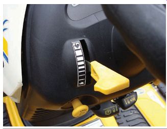
FIG. 1 Engines with manual throttle control often use a control linkage
as the throttle may be operated at a distance from the carburetor. Shown is
a throttle control mechanism on the dashboard for easy access.
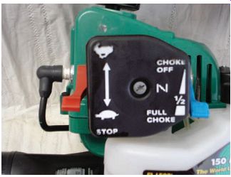
FIG. 2 Manual throttle control attached directly to the engine.
MANUAL THROTTLE CONTROL
A manual throttle control system is an engine speed control system in which the operator sets the engine speed by positioning the carburetor throttle valve in a particular position. Engines with manual throttle control often use a control linkage, as the throttle may be operated at a distance from the carburetor (FIG. 1) or the controls may be installed directly on the engine (FIG. 2). The throttle linkage in most power equipment engines is operated with a hand lever. When used in outdoor power equipment, the controls are found commonly on the handle (such as on a lawnmower) or the dashboard (such as on a lawn tractor) of the machine, depending on the type of equipment. The opera tor sets the speed by moving the throttle linkage to the desired engine speed. Along with manual control, the engine governor also assists with the control of the engine speed.
A throttle cable is used to transfer movement from the lever to the throttle valve. The throttle cable has a flexible metal housing. The out side housing is solidly mounted. A cable inner wire is free to move back and forth inside the cable housing (Figures 3a and 3b).
The cable inner wire goes from the throttle lever to the control arm assembly (FIG. 4). The control arm assembly is a plate with levers and screw stops for the engine controls. One end of the cable inner wire is connected to the throttle control arm. The other is connected to the control arm assembly. This linkage connects the carburetor throttle valve to the control lever assembly. As the operator moves the throttle control, the cable inner wire moves the carburetor throttle valve through the control lever assembly.
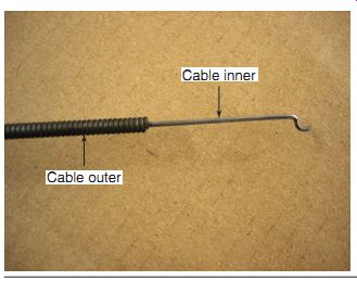
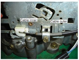
FIG. 3 A typical throttle cable inner and outer housing.
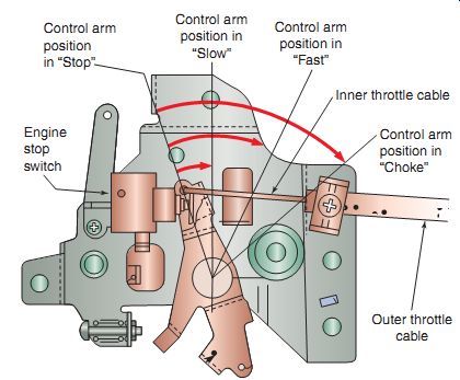
FIG. 4 A typical control arm assembly and the various throttle positions.
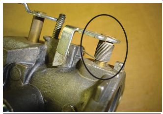
FIG. 5 A close-up of a throttle return spring.
Most power equipment engine carburetors are equipped with a throttle return spring (FIG. 5). The return spring is connected to the carburetor throttle valve to hold the throttle valve in the closed position. The spring pressure works against (opposes) the throttle valve opening. The spring pressure ensures that the throttle valve closes when the operator shuts down the throttle control.
Choke and Engine Shut-Off Switch Linkage
Manual throttle control systems often have linkages that also operate the choke. The choke is activated when the operator selects the "start" position on the engine's throttle control. A link age rod is connected to the manual control lever.
The linkage rod is connected to the choke lever on the carburetor. The choke plate is located closest to the air filter side of the carburetor.
The choke lever moves the choke valve in the carburetor throat into a closed position. After engine start-up, the operator can set the manual control to the "run" position. The linkage rod moves the choke lever from a closed position to an open position.
Many engines have an ignition shut-off switch that is part of the throttle control lever assembly. The shut-off switch has a contact that is activated by the throttle control lever.
In the "stop" position, the throttle control lever touches the shut-off switch contact.
This provides a path to ground for the primary wire of the ignition coil, which shuts the engine off. When the manual control is set on start or run, the throttle lever is moved out of contact with the shut-off switch. This removes the ground path and enables spark ignition.
We will discuss ignition systems in detail in Section 15.
GOVERNOR THROTTLE CONTROL
Along with a manual throttle control lever, many power equipment engines use a governor. An engine governor is a throttle control system that senses engine load and automatically adjusts engine speed when required. The governor throttle control system has three main functions:
- Protect the engine from over-revving
- Maintain a safe blade or equipment speed
- Match the engine speed to engine load demands
The two most common types of governors used in power equipment engines are the air vane and centrifugal types, although electronic governors are beginning to be used by some manufacturers. Here, we will concentrate on the most common types that you will see.
All engines develop maximum horsepower (hp) at a specific crankshaft revolutions per minute (rpm). For example, an engine's maximum power might be 4 hp at an engine speed of 3,600 rpm (FIG. 6). Operating the engine below 3,600 rpm will result in less power but longer engine life. Operating the engine above 3,600 rpm will result in a shorter engine life. High engine speeds create more heat, friction, and wear. Operating an engine at too high a speed for too long can break internal components such as a connecting rod or piston. The governor system prevents excessive engine speed.
Engine Speed and Load
The governor is designed to match the engine speed to the engine load. For example, during lawn mowing, you might set engine speed to "fast" and start cutting the grass. As you mow, you may run into some high grass. The engine has to work very hard to cut the high grass.
The engine will start to slow down because of the high engine load. As you move the mower over a sidewalk, the blade stops cutting any grass. The engine speeds up because of low engine load. Without a governor, you would have to manually increase and decrease engine speed all the time (FIG. 7).
The governor keeps the engine running at a steady speed by opening or closing the throttle valve. The governor closes the throttle valve for low engine loads. It opens the throttle for more power for high engine loads. The governor senses these load conditions and makes the throttle adjustments automatically (FIG. 8). There are two types of governors used in power equipment engines: air vane and centrifugal governor systems.
Governor adjustments vary between engine manufacturers. Adjustment procedures are found in service manuals.
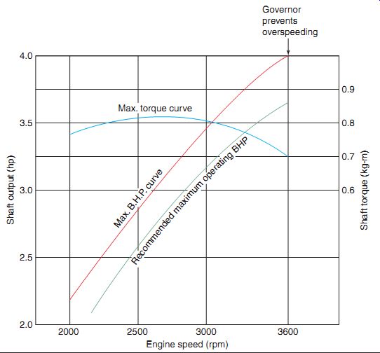
FIG. 6 A typical engine power curve.
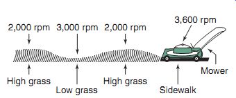
FIG. 7 A non-governed engine will change engine speed as the engine's
load increases and decreases.
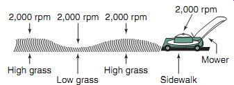
FIG. 8 A governed engine matches engine speed to engine load.
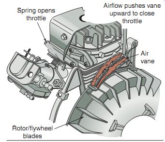
FIG. 9 An air vane is a flat piece of plastic or steel mounted on a pivot
above the flywheel.
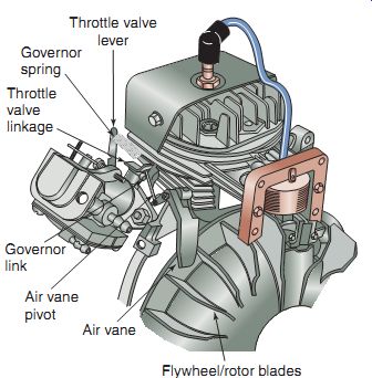
FIG. 10 Various parts of an air vane governor system.
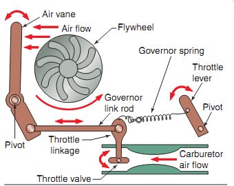
FIG. 11 The air vane governor uses opposing forces to match engine speed
to engine load, as illustrated here.
Air Vane Governors
An air vane governor uses air flow coming off the flywheel to regulate throttle opening to control engine load. The air vane governor is also sometimes called a pneumatic governor. These governors are seen commonly in less expensive engines. An advantage of an air vane governor for the manufacturer is its lower cost to produce, whereas its primary disadvantage is that it's not as responsive to the needs of the engine.
An air vane is a flat piece of plastic or steel mounted on a pivot above the flywheel (FIG. 9). The air vane is connected to the carburetor throttle valve linkage by a small link age rod. This rod is called a governor link.
The throttle lever is mounted on a pivot.
The lever is connected to one end of a spring called the governor spring. The other end of the governor spring is connected to the throttle valve linkage (FIG. 10).
The air vane governor uses opposing forces to match engine speed to engine load (FIG. 11).
The first force comes from the air flow off the flywheel, which pushes against the air vane.
This force goes to the throttle valve through the governor link rod. The air vane movement senses high or low engine load from the speed of the air flowing from the cooling fins on the fly wheel. The faster the engine runs (lower the engine load), the higher the flywheel air flow.
High air flow against the vane causes the governor link rod to move the throttle valve toward a closed position, which in turn will slow the engine's rpm down.
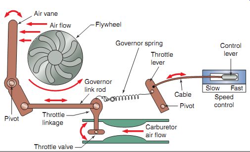
FIG. 12 The operation of a remote throttle control.
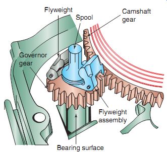
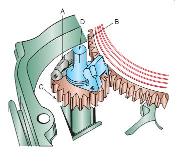
FIG. 13 The centrifugal (also known as mechanical) governor operated with
a gear that meshes with the camshaft gear.
The opposing force comes from the governor spring. The governor spring is connected to the throttle valve linkage. The spring tension is in a direction to hold the throttle valve open. The spring tension is set to hold a high enough engine speed for high engine load. As the engine load gets lower (such as a lawnmower passing over a sidewalk or a patch of low grass), its speed begins to increase. High air flow on the air valve will overcome the governor spring pressure and slow the engine.
The engine slows down when it comes to a heavy load such as when a mower cuts through high grass. The lower air flow on the air vane allows the governor spring tension to open the throttle valve, which increases engine speed. The governor air vane constantly moves back and forth in response to engine load and maintains a constant engine speed.
When engine loads are low, the engine speed increases. When this occurs, the air vane closes the throttle valve by overcoming the governor spring which, as mentioned, is used to open the throttle valve when engine loads are high.
Movement of the throttle control lever from "slow" to "fast" increases governor spring tension (FIG. 12). The higher governor spring tension holds the throttle valve open with more force. This causes a higher governed engine speed. Moving the lever back to "slow" lowers the governor spring tension. This results in a lower governed engine speed.
Centrifugal Governors
Instead of the air vane type, most of today's power equipment engines use a centrifugal governor. A centrifugal governor uses centrifugal force to regulate throttle opening. This type of governor is also called a mechanical governor. The centrifugal force is generated by rotating flyweights inside the engine crankcase.
Just as with the air vane governor, a centrifugal governor works to maintain a constant engine rpm as engine load increases or decreases.
Although it may cost more to manufacture an engine with a centrifugal governor, it responds to the needs of the engine quickly and effectively, so that most manufacturers are using them in place of the air vane type of governor.
The parts of a centrifugal governor are located inside the engine crankcase (FIG. 13). The centrifugal governor is housed on a gear and shaft driven by the engine's camshaft gear. The shaft fits into a bearing surface in the crankcase. The teeth on the governor gear mesh with the teeth on the camshaft gear.
When the engine is running, the rotating cam shaft causes the governor gear to rotate. Two specially shaped weights, called flyweights, fit through a pivot on the governor gear. The fly weights have a specially designed arm formed on the end. The arms make contact to a spool that fits over the governor shaft that moves up and down as the arms flyweights move.
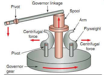
FIG. 14 The operation of a centrifugal governor.
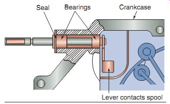
FIG. 15 The governor rod fits in the crankcase and has a lever that contacts
the governor spool. The lever moves as the spool moves.
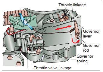
FIG. 16 Movement of a governor rod.
As the engine runs faster, the camshaft gear rotates the governor gear at a higher speed. The speed of the governor gear creates a centrifugal force, which causes the flyweights to move out ward (FIG. 14). The outward movement, however, is restricted by the mounting pivots.
When they move outward, the flyweight arms push the spool up the governor shaft. Linkage in contact with the spool transfers the movement outside the engine. As the engine slows down, spring pressure on the linkage causes the fly weights to retract, which in turn allows the spool to move back down the governor shaft.
The movement of the governor spool is transferred outside the engine by a governor rod (FIG. 15). The rod goes through the engine crankcase cover. It's supported on bearings so that it can rotate freely in the cover. There is a seal on the end of the rod to prevent engine oil from leaking out of the engine between the rod and the cover. A lever is attached on the inside end of the rod that maintains constant contact with the governor spool.
Movement of the governor spool up and down in response to engine speed causes the governor rod to rotate back and forth (FIG. 16). The governor rod is connected to a lever on the outside of the engine. A governor spring is connected to the lever. The governor spring opposes the force of the governor weights. The governor spring tension keeps the governor rod in contact with the governor spool.
The governor lever is connected through a throttle linkage rod to the carburetor throttle valve. Movement of the governor rod causes movement to the governor lever. The lever moves the throttle linkage and throttle valve.
The governor spring tension opposes the linkage movement and works to hold the throttle open.
The governor spring also retracts the flyweights when engine speed and centrifugal force drop.
As with the air vane system, a throttle cable may be connected to the centrifugal governor linkage to provide remote throttle control (FIG. 17). Movement of a control lever on the equipment handle moves the throttle cable. The cable movement changes the tension of the governor spring. Increasing governor spring tension causes a higher governed speed. Decreasing governor spring tension causes a lower governed speed.
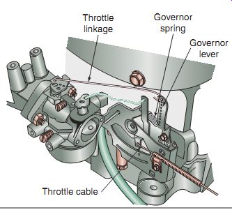
FIG. 17 A throttle cable can be attached to a centrifugal governor system,
as illustrated here.
Summary
A manual throttle control system is an engine speed control system in which the operator sets the engine speed by positioning the carburetor throttle valve in a particular position.
An engine governor is a throttle control system that senses engine load and automatically adjusts engine speed when required.
An air vane governor is a governor that uses air flow coming off the flywheel to regulate throttle opening to engine load.
A centrifugal governor is a governor that uses centrifugal force to regulate throttle opening.
QUIZ
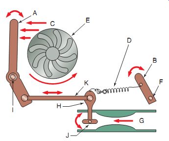
1. The following figure shows an governor system.
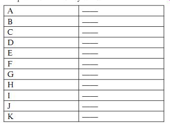
2. Match the letters on each component in the figure (see left) to the relevant number provided in the key table.
3. The following figure shows a governor system.
4. Match the letters on each component in the above figure to the relevant number provided in the key table.