AMAZON multi-meters discounts AMAZON oscilloscope discounts
Goals:
- Describe the three major functions of an ignition system
- Describe the common components found in all types of ignition systems
- Name the two major electrical circuits used in an ignition system
- Name the different types of ignition systems
- Describe how electric starter systems used in power equipment engines operate
===========
INTRODUCTION
In Sections 13 and 14, you learned the basics of electricity and charging systems. You also learned about battery-powered electrical circuits found in power equipment engines.
In this section, you'll learn about the different types of ignition systems. First, we'll explain basic ignition system operation and identify the main components in an ignition system. Then, we'll look at the different types of ignition systems and learn about ignition system timing.
Finally, we'll discuss electric starting systems found in power equipment engines.
Do you remember the stages of operation in a two-stroke and a four-stroke engine? In each cylinder of the engine, the piston rises during the compression stage to compress the air-fuel mixture in the combustion chamber. Just before the piston reaches the top-dead center (TDC), a spark plug fires in the cylinder and ignites the compressed air-fuel mixture. The ignition of the air-fuel mixture forces the piston down in the cylinder, producing the power stage. The power produced by the ignition of the air-fuel mixture turns the crankshaft, which in turn keeps the piston moving and the engine running.
One of the requirements for an efficient engine is the correct amount of heat, delivered at the right time. This requirement is met by the ignition system. The ignition system supplies properly timed, high-voltage surges to the spark plug(s). These voltage surges cause combustion inside the cylinder.
The ignition system must create a spark, or current flow (FIG. 1), across each pair of spark plug electrodes at the proper instant, under all engine operating conditions. This may sound relatively simple, but when one considers the number of spark plug firings required and the extreme variation in engine operating conditions, it's easy to understand why ignition systems are so complex.
Almost all ignition systems used in power equipment engines fire the spark plug once per revolution of the crankshaft. When this occurs on a four-stroke engine, it's known as a wasted spark, as the cylinder requires only one spark per every two revolutions of the crankshaft. These spark plug firings must also occur at the correct time and must generate the correct amount of heat. If the ignition system fails to perform these functions properly, fuel economy, engine performance, and emission levels are adversely affected.

FIG. 1 The sole purpose of an ignition system is to provide a spark that
ignites the air- fuel mixture in the combustion chamber of an engine. Honeywell
International Inc.
POWER EQUIPMENT ENGINE IGNITION SYSTEMS
The sole purpose of an ignition system is to provide a spark that will ignite the air-fuel mixture in the combustion chamber. The spark must be timed to occur at a precise point relative to the position of the piston as it reaches TDC on the engine's compression stroke. The difference between various ignition systems lies in how the spark is activated. In some of today's larger power equipment engines, ignition systems are used in unison with electronic fuel injection systems.
For each cylinder in an engine, the ignition system has the following three main functions:
It must generate an electrical spark that has enough heat to ignite the air-fuel mixture in the combustion chamber.
It must maintain that spark long enough to allow for the combustion of all the air and fuel in the cylinder.
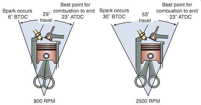
FIG. 2 As an engine's speed increases, a spark must be delivered sooner
to allow for complete combustion of the air-fuel mixture. This is known as
ignition advance.
It must deliver a spark so that combustion can begin at the right time during each compression stroke of the piston.
When the combustion process is completed, a very high pressure is exerted against the top of the piston. This pressure pushes the piston down on its power stroke and this is the force that gives the engine power. For an engine to produce the maximum amount of power it can, the maximum pressure from combustion should be present when the piston is at 10-23° after top-dead center (ATDC). Because combustion of the air-fuel mixture within a cylinder takes a short period of time, usually measured in thousandths of a second (milliseconds), the combustion process must begin before the piston is on its power stroke. Therefore, the delivery of the spark must be timed to arrive at some point just before the piston reaches TDC.
Determining how much time before TDC the spark should begin is complicated. This is because even as the speed of the piston moving from its compression stroke to its power stroke increases, the time needed for combustion stays about the same. This means that, as the engine's speed increases, the spark should be delivered earlier (FIG. 2). However, at high speeds, as the engine has to provide more power to do more work, the high load on the crankshaft tends to slow down the acceleration of the piston, in which case the spark needs to be accordingly delayed.
Figuring out when the spark should begin gets more complicated because the rate of combustion varies, depending on certain factors.
Higher compression pressures tend to speed up combustion. A higher-octane gasoline ignites less easily and requires more burning time.
Increased vaporization and turbulence tend to decrease combustion times. Other factors, including intake air temperature, humidity, and barometric pressure, also affect combustion.
Because of all of these complications, delivering the spark at the right time is a difficult task.
How does an ignition system produce a spark, time it perfectly, and keep making sparks over and over again? Let's find out.
Ignition Timing
Ignition timing refers to the precise time spark occurs. It's specified by referring to the position of a manufacturer-determined piston (generally the No. 1 piston on the crankshaft in multi cylinder engines) in relation to crankshaft rotation. Ignition timing reference marks are sometimes located on the engine's crankshaft flywheel/rotor to indicate the position of the piston.
Power equipment engine manufacturers specify initial or base ignition timing. Some engines don't require such markings because the ignition systems are fixed in one position and are not adjustable.
When the marks are aligned at TDC, the piston is at the TDC of the engine's stroke. Additional marks indicate the required number of degrees of crankshaft rotation before top-dead center (BTDC) or ATDC. In a majority of engines, the initial timing is specified at a point between TDC and 15° BTDC, depending on the manufacturer's predetermined specification.
Although most power equipment engines are designed to run over a relatively small engine rpm range (for instance, 500-3,600 rpm), if optimum engine performance is to be maintained, the ignition timing of the engine must change as the operating conditions of the engine change.
These conditions affect the speed of the engine and the load on the engine. Therefore, all ignition timing changes are made in response to these primary factors.
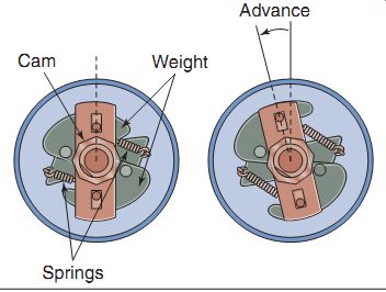
FIG. 3 A centrifugal advancer uses a set of pivoted weights and springs
connected to the shaft holding the triggering device attached to it (left).
When engine speed increases, the weights move outward, shifting the plate where
the triggering device is mounted (right). This shifting of the plate causes
the triggering device its signal earlier, causing an advance in the ignition
timing.
Ignition Timing Advance
Power equipment engines generally run at relatively stable engine speeds, and so ignition advance isn't required. But in some engines, speed varies a lot and ignition timing needs to be varied accordingly. In such cases, it's necessary to advance or retard ignition in some engines. Two methods are used in power equipment engines to advance ignition.
Ignition systems in older power equipment engines that require ignition timing advance are equipped with centrifugal advance mechanisms (FIG. 3), which advance or retard ignition timing in response to engine speed. Centrifugal advance uses a set of pivoted weights and springs connected to a shaft with the point cam (crankshaft or camshaft) attached to it. When engine speed increases, the weights move outward, shifting the plate where the triggering device is mounted. This shifting of the plate causes the triggering device to receive its signal earlier, causing an advance in the ignition timing.
Most all modern day power equipment engines that require advance use an electronic advance system to control the ignition. Electronic advance systems require no adjustment, have no mechanical parts, and therefore don't wear out. The design eliminates the need for maintenance. Electronic advance systems use multiple sensors to determine the correct timing advancement for any given condition. They offer a greater variety of timing choices for different engine running conditions instead of basically only two, as is case with centrifugal advance systems.
Engine rpm and Turbulence
At higher rpm, the crankshaft turns through more degrees in a given period of time. If combustion is to be completed by a particular number of degrees ATDC, ignition timing must occur sooner-or be advanced-by the use of a mechanical or electrical advancer. The advancer is generally attached on the crankshaft.
Another complication that arises at high rpm is the turbulence (swirling) of the air-fuel mixture, which increases with rpm. This causes the mixture inside the cylinder to turn faster.
Increased turbulence requires that ignition must occur slightly later-or be slightly retarded-by the use of the advancer.
These two factors-high rpm and increased turbulence-must be balanced for optimum engine performance. Therefore, although ignition timing must be advanced as engine speed increases, the amount of advance must be decreased to compensate for the increased turbulence.
Engine Load
The load on an engine is related to the work it must do. For example, cutting deep grass or pulling extra weight increases engine load. At higher loads, there is greater resistance on the crankshaft; therefore, the piston has a harder time moving through their strokes.
Under light loads and with the throttle partially open, a high vacuum exists in the intake manifold. The amount of air-fuel mixture drawn into the manifold and cylinders is small.
On compression, this thin mixture produces less combustion pressure, and combustion time is increased. To complete combustion by the desired degrees ATDC, ignition timing must be advanced.
Under heavy loads, when the throttle is open fully, a larger mass of air-fuel mixture is drawn in, and the vacuum in the manifold is low. High combustion pressure and rapid burning result.
In such cases, ignition timing must be retarded to prevent completion of burning before the crankshaft has reached the desired degrees ATDC.
Firing Order in Multi-Cylinder Engines
Up to this point, we've focused primarily on ignition timing as it relates to any one cylinder. However, the function of an ignition system extends beyond timing the spark in a single cylinder. In multi-cylinder engines, it must perform this task for each cylinder of the engine in a specific sequence.
In the case of a multi-cylinder four-stroke engine, each cylinder of the engine must produce power once in every 720° of crankshaft rotation. Each cylinder must have a power stroke at its own appropriate time. To make this possible, the pistons and connecting rods are arranged in a precise fashion called the engine's firing order. The firing order is arranged to reduce rocking and imbalance problems. Because the potential for this rocking depends on the design and construction of the engine, the firing order varies from engine to engine. Engine manufacturers simplify cylinder identification by numbering each cylinder. Regardless of the firing order used, the No. 1 cylinder always starts the firing, with the rest of the cylinders following in a fixed sequence.
The ignition system must be able to "monitor" the rotation of the crankshaft and the relative position of each piston to determine which piston is on its compression stroke. It must also be able to deliver a high-voltage surge to each cylinder at the proper time during its compression stroke. How the ignition system does these things depends on the design of the system.
BASIC IGNITION SYSTEM COMPONENTS
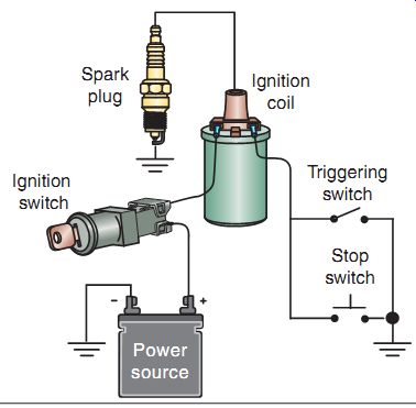
FIG. 4 The basic components of an ignition system.
FIG. 4 shows a simplified drawing of a basic ignition system. The main components of the system are the following:
- Power source
- Ignition switch
- Ignition coil
the battery that powers an ignition system can also be used to run other devices, such as lights, accessories, and electric starter systems. In contrast, most AC-powered ignition systems sup ply power only to fire the spark plug. Second, because a battery can be used to run an electric starter system, implements that contain battery systems can be started with a simple turn or push of an electric starter switch. AC-powered ignition systems are generally activated by manually starting the engine with a pull-start device.
Therefore, larger power equipment engines, such as those used in tractors, generally use battery systems, whereas smaller power equipment engines, such as lawnmowers, generally use AC-powered systems.
Advantages of the AC Generator Power Source System
The AC-powered ignition system has certain advantages over the battery as a power source. First, when a power equipment engine uses an AC generator, no onboard battery is needed. Batteries are heavy and inconvenient on implements such as lawnmowers and handheld blowers. Second, no separate charging system is required with an AC generator, whereas batteries require a charging system to keep them working.
Ignition Switch
The ignition switch allows the power source to provide electrical power to the ignition sys tem. It's generally a key-type switch that also powers all components that use a power source, such as lights and accessories.
Ignition Coil
An ignition coil is essentially a transformer that consists of two wire windings wound around an iron core (FIG. 5). The first winding is called the primary winding, and the second winding is called the secondary winding.
The secondary winding has many more turns of wire than the primary winding.
In an ignition coil, one end of the coil's primary winding is always connected to a power:
- Spark plug
- Triggering switch
- Stop switch
All ignition systems contain these components. The difference is how the components function. We'll take an in-depth look at each of these components, beginning with the power source.
Power Sources
In power equipment engine ignition systems, there are just two power source options. These power sources are the battery [for direct current (DC)] or the AC generator [for alternating cur rent (AC)].
In a battery ignition system, a battery is connected to the ignition coil. A triggering switch device is used to alternately turn the DC voltage on and off for its operation.
AC generator power sources are far more common than battery systems for power equipment engines, and in most cases, they're designed to be run without a battery. The AC-powered ignition system uses the principles of magnetism to produce a voltage. In Section 13, we discussed magnetic induction and generators. Remember that when a conductor wire is moved through a magnetic field, a voltage is induced in the conductor. It's also true that if a magnet is moved near a conductor, a voltage is induced in the conductor. If this conductor wire is connected to a complete circuit, current will flow in the circuit.
In an AC ignition system, permanent magnets are installed in the engine's flywheel/rotor. As the flywheel/rotor turns, the moving magnets cause a voltage to be induced in the ignition coil.
We'll look at the design and operation of both the AC-powered system and the battery system in detail a little later in this section. For now, just keep in mind that the power source for a power equipment engine or ignition system can be provided by either AC power or a battery.
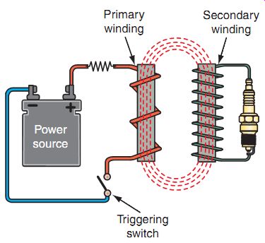
FIG. 5 A basic transformer. When a voltage is applied to the primary
winding, a voltage is induced into the secondary winding that's many times
greater than the voltage in the primary winding.
Advantages of the Battery Power Source System
Battery-type ignition systems have some advantages over AC ignition systems. First, source. Depending on the type of ignition sys tem, the power source may be a battery (providing DC) or a flywheel/rotor with a permanent magnet (providing AC). Either type of power source can be used to apply a voltage to the primary winding of the coil.
When current passes through the primary winding of the coil, a magnetic field is created around the iron core. As the magnetic field expands, the magnetic lines of flux cut through the wires of the secondary winding and induce a voltage in the secondary winding. If the current in the primary winding is switched off, a volt age is again induced into the secondary winding by the magnetic lines of flux, which again cut through the secondary winding. The direction of current induced into the secondary winding is reversed each time the current in the primary is turned on and off. This is because the magnetic lines of force around the iron core cut through the secondary winding in opposite directions as the magnetic field expands and collapses.
Because the secondary winding of the coil has many more wire coils than the primary, the voltage produced in the secondary winding is much higher than the original voltage applied to the primary winding. In a typical power equipment engine ignition system, the power source supplies about 12 volts to the primary winding of the ignition coil. From this 12-volt input, the ignition coil produces 20,000-60,000 volts or even more at the secondary coil.
The secondary winding of the coil is always connected to the spark plug through the spark plug wire. Because the spark plug wire needs to carry the high voltage and prevent it from arcing to ground, it's heavily insulated.
When the magnetic field in the ignition coil expands or collapses (coils are designed to do one or the other), the high voltage in the secondary is applied to the spark plug and causes a spark to jump across the spark plug gap. The spark ignites the air-fuel mixture, enabling the power equipment engine to run.
It's important to remember that the high volt age in the secondary winding of the coil is produced each time the primary current is turned on or off. In a collapsing-field ignition system, the high voltage from the secondary winding is used when the current to the primary winding is switched off. In a rising-field ignition system, the high voltage from the secondary winding is used when the current to the primary winding is switched on. This means that all ignition systems need some type of a device that will keep turning the current from the power source on and off.
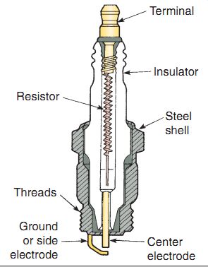
FIG. 6 The parts of a typical spark plug.
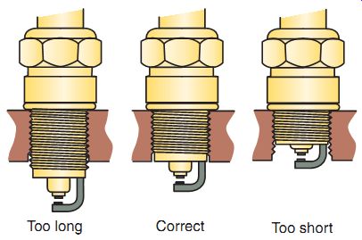
FIG. 7 Spark plug reach is crucial because the plug's air gap must be
properly placed in the combustion chamber to produce the correct amount of
heat. If a plug's reach is too short, its electrodes are in a pocket, and the
arc does not adequately ignite the mixture. If the plug's reach is too long,
the exposed plug threads can hit the piston or get so hot they will ignite
the air-fuel mixture at the wrong time.
Spark Plug
The spark plug provides the crucial air gap across which the high voltage from the secondary coil causes an arc or spark. The main parts of a spark plug are a steel shell; a ceramic core or insulator, which acts as a heat conductor; and a pair of electrodes, one insulated in the core and the other grounded on the shell. The shell holds the ceramic core and electrodes in a gas tight assembly and has threads for plug installation in the engine (FIG. 6). The insulator is made of ceramic materials to provide for increased durability and strength. The shell may be coated with a corrosion-resistant material or materials that prevent the threads from seizing to the cylinder head. Most of today's spark plugs have a resistor (generally about 5,000 or 5K ohms) between the top terminal and the center electrode. Some spark plugs use a semiconductor material to provide for this resistance. The resistor reduces radio frequency interference (RFI), which can interfere with, or damage, radios, computers, and other electronic accessories. If an engine is equipped with resistor plugs, the same should be installed when the originals are replaced.
The terminal post on top of the center electrode is the connecting point for the spark plug cable. Current flows through the center of the plug and arcs from the tip of the center electrode to the ground electrode. The center electrode is surrounded by the ceramic insulator and is sealed to the insulator with copper and glass seals. These seals prevent combustion gases from leaking out of the cylinder. Ribs on the insulator increase the distance between the terminal and the shell, to help prevent electric arcing on the outside of the insulator. The steel spark plug shell is crimped over the insulation, and a ground electrode, on the lower end of the shell, is positioned directly below the center electrode. There is an air gap between these two electrodes.
Spark plugs come in many sizes and designs to accommodate different engine designs.
Spark Plug Reach
One important design characteristic of spark plugs is spark plug reach (FIG. 7). This refers to the length of the shell from the contact surface at the seat to the bottom of the plug.
Spark plug reach is crucial because the plug's air gap must be placed properly in the combustion chamber to produce the correct amount of heat.
If a plug's reach is too short, its electrodes are in a pocket and the arc is not able to adequately ignite the mixture. If the reach is too long, the exposed plug threads can hit the piston or get so hot they will ignite the air-fuel mixture at the wrong time and cause preignition. Preignition, as we know, is a term used to describe abnormal combustion, which is caused by something other than the heat of the spark.
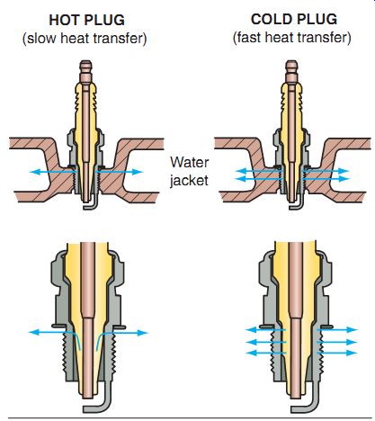
FIG. 8 Spark plug heat range: hot versus cold.
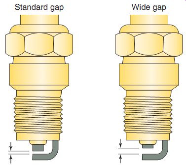
FIG. 9 Spark plug gaps.
Heat Range
When the engine is running, most of the spark plug's heat is concentrated on the center electrode. Heat is quickly dissipated from the ground electrode because it's attached to the shell, which is threaded into the cylinder head.
In liquid-cooled engines, coolant circulating in the head absorbs the heat and moves it through the cooling system. In air-cooled engines, the heat is absorbed through the cylinder head.
The heat path for heat in the center electrode is through the insulator into the shell and then to the cylinder head. The heat range of a spark plug is determined by the length of the insulator before it contacts the shell. In a cold spark plug, there is a short distance for the heat to travel up the insulator to the shell. This short path for heat means the electrode and insulator maintain little heat between firings (FIG. 8).
In a hot spark plug, the heat travels farther up the insulator before it reaches the shell. This provides a longer heat path and the plug retains more heat. A spark plug needs to retain enough heat to clean itself between firings, but not so much that it damages itself or causes premature ignition of the air-fuel mixture in the cylinder.
The heat range is indicated by a code imprinted on the side of the spark plug, usually on the porcelain insulator.
Spark Plug Gap
Correct spark plug air gap (FIG. 9) is essential for achieving optimum engine performance and long plug life. A gap that is too wide requires a higher voltage to jump the gap.
If the required voltage is greater than what is available, misfiring results. Misfiring occurs because of the inability of voltage generated at the secondary coils to jump the gap or maintain the spark. Alternatively, a gap that is too narrow requires lower voltages and can lead to rough idle and prematurely burned electrodes, due to higher current flow. Also, a misfire may occur if a spark plug terminal is loose.
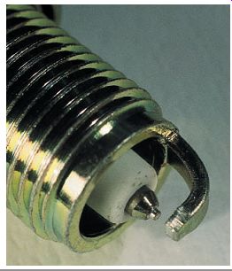
FIG. 10 A platinum-tipped spark plug.
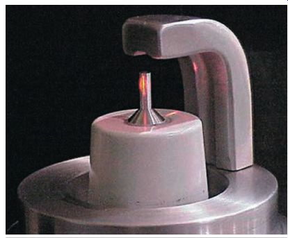
FIG. 11 This spark plug has a small-diameter iridium center electrode
and a grooved ground electrode. Denso Sales California, Inc.
Electrodes
The materials used in the construction of a spark plug's electrodes determine the longevity, power, and efficiency of the plug. The construction and shape of the tips of the electrodes are also important.
The electrodes of a standard spark plug are made out of copper, and some use a copper- nickel alloy. Copper is a good electrical conductor and offers resistance to corrosion.
Platinum electrodes are used to extend the life of a spark plug (FIG. 10). Platinum has a much higher melting point than copper and is highly resistant to corrosion. Although platinum is an extremely durable material, it's an expensive precious metal; therefore, platinum spark plugs cost more than copper spark plugs. Also, platinum isn't as good a conductor as copper. Spark plugs are available with only the center electrode made of platinum (called single-platinum) and with the center and ground electrodes made of platinum (called double-platinum). Some platinum plugs have a very small center electrode combined with a sharp-pointed ground electrode designed for better performance.
Until recently, platinum was considered the best material to use for electrodes, because of its durability. However, another material with several advantages is iridium alloy. Iridium is six times harder, eight times stronger, and has a melting point that is 1,200° higher than that of platinum. Iridium is a precious, silver-white metal and one of the densest materials found on earth. A few spark plugs use an iridium alloy as the primary metal complemented by rhodium to increase oxidation wear resistance. This iridium alloy is so durable that it allows for an extremely small center electrode. A typical copper-nickel plug has a 2.5-mm-diameter center electrode, whereas a platinum plug has a diameter of 1.1 mm. An iridium plug can have a diameter as small as 0.4 mm (FIG. 11), which means firing voltage requirements are decreased.
Iridium is also used as an alloying material for platinum.
Electrode Designs
Spark plugs are available with many shapes and numbers of electrodes.
When trying to ascertain the advantages of each design, remember the spark is caused by electrons moving across an air gap. The electrons will always flow in the direction of least electrical resistance.
The shape of the ground electrode may also be altered. A flat, conventional electrode tends to crush the spark, and the overall volume of the flame front is smaller. A tapered ground electrode increases flame front expansion and reduces the heat lost to the electrode. Ground electrodes in many power equipment engine spark plugs have a U-groove machined into the side that faces the center electrode. The U-groove allows the flame front to fill the gap formed by the U-shape. This ball of fire develops a larger and hotter flame front, leading to a more complete combustion.
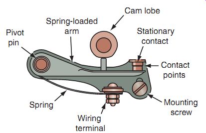
FIG. 12 A set of breaker points.
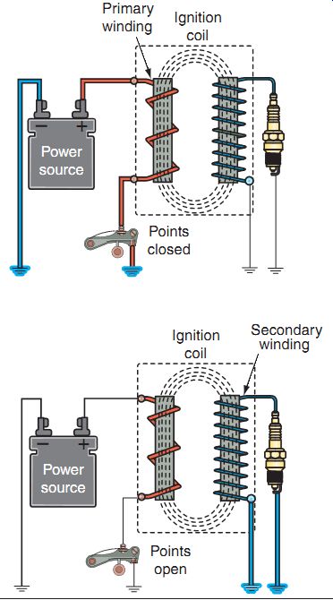
FIG. 13 Shown is the action of breaker points in a simple ignition circuit.
When the breaker points are closed, current flows through the ignition coil's
primary winding.
When the points open, the circuit is broken, and the magnetic field in the coil collapses, which induces a voltage into the coil secondary to fire the spark plug.
Triggering Switch Devices
Different types of ignition systems use different types of switching devices. There are two basic types of trigger switching devices used in power equipment engine ignition systems. Older ignition systems use a set of electrical contacts called breaker points and a condenser to do the switching. Although rarely used by any major manufacturer today, breaker points and condensers continue to be in use in millions of older power equipment engines. All modern power equipment engine systems, however, use electronic components to do the switching. In either system, the construction of the ignition coil and the spark plug remain the same.
Breaker Points and Condenser
Breaker points are mechanical contacts that are used to stop and start the flow of current through the primary windings of the ignition coil. The points are usually made of tungsten, a very hard metal that has a high resistance to heat. One breaker point is stationary (fixed), and the other point is movable and insulated from the stationary point. The movable con tact is mounted on a spring-loaded arm, which holds the points together. FIG. 12 shows a simplified drawing of a set of breaker points.
When the two breaker points touch, the ignition circuit is complete and the primary winding of the ignition coil is energized. When the end of the spring-loaded movable breaker point is pressed, its contact end moves apart from the stationary breaker point. This opens the circuit and the flow of current stops. Each time the breaker points move apart, the spark plug fires.
This action is shown in FIG. 13.
The spring mounted under the movable point holds the movable breaker point against the cam. The movable breaker point is moved to the open position by a turning cam with a lobe.
In most cases, the cam is located on the crank shaft. The lobe on the cam forces the movable breaker point away from the stationary point, and the spark plug fires.
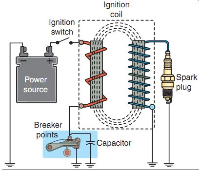
FIG. 14 A typical battery-powered breaker point system.
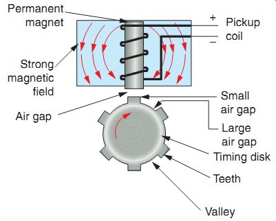
FIG. 15 A magnetic-pulse generator is located near the engine's crankshaft
or camshaft in most cases. It consists of two parts: a timing disc (also known
as a reluctor) and a pickup coil.
Another important component of a breaker points system is the condenser (also called a capacitor). Remember that each time the breaker points touch, current flows through them. Unless this current flow is controlled in some way, a spark or arc will occur across the breaker points as they move apart. If this sparking is allowed to occur, the breaker points will arc, burn, and fail to operate properly. The points would also absorb the electrical energy and reduce the out put voltage of the ignition coil.
For these reasons, a condenser is used to control the current as it flows through the breaker points. A condenser absorbs current and stores it, like a miniature battery. In an ignition circuit, the condenser is connected across-or parallel to-the breaker points. As the breaker points begin to separate, the condenser absorbs the current created by the collapsing magnetic field. When the crankshaft or camshaft is turned, the timing disc moves through the magnetic field. As the timing disc teeth approach the pickup coil, a voltage is induced, and this is used to control the voltage to the primary side of the ignition coil, just as the opening and closing of the contact points in the breaker-points and-condenser switching system. A specific, manufacturer-determined air gap is required to ensure that a signal of appropriate strength is being produced.
Hall-Effect Sensor
The Hall-effect sensor or switch is the most commonly used engine position sensor used in a power equipment engine that uses an electronic ignition system. There are several reasons for this. Unlike the magnetic pulse generator, the Hall-effect sensor produces an accurate voltage signal across the entire rpm range of the engine. Furthermore, a Hall-effect switch produces a square-wave pattern that is more compatible with the digital signals required by onboard computers.
Functionally, a Hall-effect switch performs the same tasks as a magnetic-pulse generator.
But the Hall-effect switch's method of generating voltage is quite unique. It's based, as you may guess, on the Hall-effect principle. This field around the primary winding of the coil so that it can't jump between the points and make a spark.
The breaker-points-and-condenser switching system can be used in both AC and battery powered ignition systems. FIG. 14 shows a breaker-points system. Note the location of the breaker points and condenser in the circuit.
Electronic Trigger Devices
When an electronic ignition system is used in a power equipment engine, a sensor is used to monitor the position of the crankshaft and control the flow of current to the primary side of the ignition coil. These sensors primarily include magnetic-pulse generators and Hall-effect sensors. An electronic switch completely eliminates the need for breaker points and a condenser.
Magnetic-Pulse Generator
A magnetic pulse generator is located generally on the engine's crankshaft or camshaft and consists of two parts: a timing disc (also known as a reluctor) and a pickup coil ( FIG. 15). The pickup coil consists of a length of wire wrapped around a permanent magnet. The magnetic-pulse generator operates on the basic electromagnetic principle that voltage can be induced only when a conductor moves through a magnetic states that if a current is allowed to flow through a thin conducting material and that material is exposed to a magnetic field, voltage is produced in the conductor. In essence, a Hall-effect switch is either on or off. It also uses a timing disc that is used to switch the power on and off as it passes by the sensor.
Stop Switch
Once an engine is started, it will keep running until it runs out of fuel or is put under a heavy-enough load to cause it to stall. The stop switch provides a convenient means to stop the engine.
Different types of stop switches are found in different types of ignition systems. In some power equipment engines, the stop switch interrupts the flow of electricity to the spark plug by giving the electrical current an easier path to ground. This type of switch consists of a button that grounds the ignition system (FIG. 4).
In other engines, the stop switch is designed to prevent the flow of electricity through the primary winding of the ignition coil. This type of stop switch is connected in series with the primary side of the ignition coil. When you turn the switch to the Off position, the ignition circuit is made to open and the engine stops.
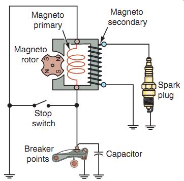
FIG. 16 A high-tension magneto system.
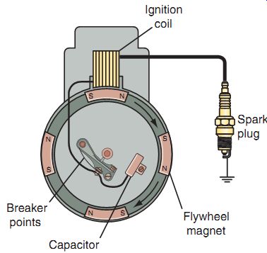
FIG. 17 A high-tension magneto ignition system. A permanent magnet is
mounted near the edge of the flywheel. As the flywheel turns, the magnet passes
near the ignition coil and induces a voltage in the primary winding.
TYPES OF IGNITION SYSTEMS
Now that you understand how a basic ignition system in a power equipment engine operates, let's take a closer look at the construction of some types of ignition systems. The two general types are the:
- Breaker point ignition system
- Electronic ignition system
There are two types of breaker point systems.
(1) The magneto breaker point ignition system is usually found in older machines, where a volt age is needed only to power the spark plug-not a starter system or lights. (2) The battery-and points ignition system is found in most of the older power equipment engines that have electric starter systems and lights.
Electronic ignition systems of one type or another are found in virtually all modern day power equipment engines.
All types of ignition systems contain the same basic components. The magneto system and the battery system are similar, except that they use different power sources. Electronic
ignition systems use electronic components to perform the switching function, but their power source can be either a battery or an AC generator. Finally, all ignition systems have a switch device to turn the ignition system on and off.
Magneto Ignition Systems
In magneto ignition systems in older power equipment engines without any lights or a battery, the AC source may have the sole function of operating the ignition system. In other models that include lighting systems, one AC generator coil may be used for ignition, and another for lighting. All magneto ignition systems operate without a battery, or are independent of the battery if one is used for the operation of other electrical functions.
The magneto ignition system uses permanent magnets installed on the engine's flywheel/rotor.
Magnetos are classified as being one of three types:
- High tension
- Low tension
- Energy transfer
High-Tension Magneto Ignition System
High-tension magneto ignition systems ( FIG. 16) haven't been in use in power equipment engines for quite a few years, but they were once the most popular ignition sys tem, found in small engines. With this ignition system, the ignition coil (magneto primary and secondary windings) is mounted in a stationary position near the flywheel/rotor. When the fly wheel/rotor turns, the magnets induce a voltage in the primary winding of the ignition coil.
The position of the magnets on the flywheel/rotor is important. To generate the volt age at the exact time needed, the magnets in the flywheel/rotor must be properly aligned. This means that the flywheel/rotor must be located exactly in the position required on the crank shaft. The flywheel/rotor is held in position on the crankshaft by a flywheel/rotor key, which is inserted into matching slots that are cut into the crankshaft and flywheel/rotor.
The gap between the edge of the flywheel/ rotor and the iron core of the ignition coil is an important specification in a high-tension magneto ignition system. The engine manufacturer's specification for this gap is of the order of thousandths of an inch or hundredths of a milli meter. This is one of the specifications that must be checked when you're servicing a high-tension magneto ignition system.
Now, let's take a closer look at the operation of a high-tension magneto system. FIG. 17 illustrates a simplified drawing of a high-tension magneto system in operation. You can see the breaker points at the center of the flywheel/ rotor. In actual practice, the breaker points are located underneath the flywheel/rotor.
Remember that the ignition coil is basically a transformer and contains a primary winding and a secondary winding. In a typical high-tension magneto ignition coil, the primary winding comprises about 150 turns of fairly heavy copper wire, and the secondary winding comprises about 20,000 turns of very fine copper wire. This difference in the windings is what causes the voltage to be multiplied as it's induced by the primary to the secondary.
As the flywheel/rotor turns, the permanent magnets mounted near the edge of the flywheel/ rotor move past the ignition coil. This movement magnetizes the soft iron core (coil armature) and induces a current in the primary winding of the ignition coil. The magnetic field produced by the primary winding induces a voltage in the secondary winding. However, the buildup and collapse of the magnetic field by this action isn't fast enough to induce the voltage strong enough to fire the spark plug.
FIG. 16 A high-tension magneto system
FIG. 17 A high-tension magneto ignition system. A permanent magnet is
mounted near the edge of the flywheel. As the flywheel turns, the magnet passes
near the ignition coil and induces a voltage in the primary winding.
This is when the condenser comes in handy. The primary winding, as can be seen in FIG. 17, is connected to the breaker points. When the breaker points are closed, a complete circuit is formed, and a current flows through the primary winding to produce a magnetic field. The eccentric egg-shaped cam that is located on the crankshaft is timed to open the breaker points just as the magnetic field in the primary begins to collapse. This interrupts the current flow in the primary circuit, causing the magnetic field around the primary winding to rapidly collapse. At the same time, the condenser (which also protects the breaker points from burning) releases its charge back through the primary winding to hasten the collapse of the magnetic field. This action helps to increase the voltage induced in the secondary winding to the required high strength.
The high voltage induced in the secondary winding causes a current to flow through the spark plug wire and arc across the spark plug gap. After the high voltage in the secondary winding is released as a spark, the flywheel/rotor continues to turn until the magnet positions itself by the ignition coil again, and the process repeats itself.
Low-Tension Magneto Ignition System Not found often in power equipment engines, the low-tension magneto system is similar in operation to the high-tension magneto system.
The main difference is that the low-tension sys tem uses a separate ignition coil. The breaker points in both the high- and low-tension magneto ignition systems are connected in series with the primary circuit. When the breaker points are closed in the low-tension magneto system, the primary circuit is completed (FIG. 18). As the magneto rotor turns, AC is generated in the magneto windings and flows through the ignition coil primary winding. The primary winding in the ignition coil produces a magnetic field in the ignition coil.

FIG. 18 A low-tension magneto ignition system.
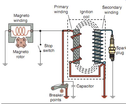
FIG. 19 An energy-transfer ignition system.
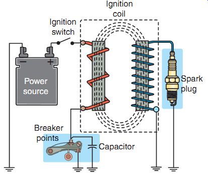
FIG. 20 The battery-and-points system uses the same type of breaker points,
condenser, and spark plug as the magneto-type ignition system, the primary
difference being the source of electrical power.
Energy-Transfer Ignition System
The energy-transfer ignition system ( FIG. 19) is another type of magneto ignition system found in power equipment engines. The primary difference between the energy-transfer system and the magneto systems is that the breaker points are connected in parallel with the primary circuit instead of in series.
By having the points wired in parallel, the primary winding in the ignition coil induces volt age into the secondary windings by using a rapid buildup of a magnetic field instead of a rapid collapse of the field.
Battery-and-Points Ignition Systems
Now, let's look at a battery-and-points ignition system. Remember that battery ignition systems were used in older street-type power equipment engines. In a battery-and-points ignition system, a battery is used to provide power to the ignition coil instead of a magneto; however, the remainder of the system is similar to the magneto systems we've discussed. The battery-and-points system (FIG. 20) uses the same type of breaker points, condenser, and spark plug as magneto-type ignition systems.
The battery used in this type of system is the lead acid storage battery (see Section 14). Besides providing electricity to power the ignition coil, the battery may also be used to power lights, electric starter systems, and other accessories.
The battery-and-points ignition system uses breaker points to trigger the ignition. The battery provides the voltage to energize the primary winding of the ignition coil. The voltage to the ignition coil is controlled by a key-operated ignition switch. When the ignition switch is turned on, power from the battery passes through the ignition switch to the primary winding of the ignition coil. The opposite end of the primary winding is connected to the breaker points and condenser.
The breaker points, the secondary winding, and the spark plug operate in exactly the same manner as in the high- and low-tension magneto systems. The contact points are opened by the breaker-point cam at the specified time. As the points open, the primary magnetic field rapidly collapses, causing a high voltage to be induced into the secondary windings. The only difference between this ignition system and the magneto ignition system is that DC (from the battery)
is used to energize the primary winding of the ignition coil in the former, instead of the AC.
When the ignition switch is turned off, the switch contacts open, and the flow of power from the battery to the primary winding of the ignition coil is stopped. As a result, the engine stops running.
Electronic Pointless Ignition Systems
Breaker-points-and-condenser ignition systems have been in use for many years, but you may see these types of ignition systems only in older power equipment engines. Newer power equipment engines come with electronic ignition systems. The reason for this is that mechanical breaker points eventually wear out and fail.
The result is poor engine performance at first and ultimately, total ignition failure. Electronic ignition systems are durable because they use permanent magnets, electronic sensors, diodes, transistors, and SCRs in place of mechanical switching components.
Except for the breaker points and condenser, electronic ignition systems use the same basic components that we've discussed. In place of the breaker points and condenser, the electronic ignition system uses an electronic ignition control module (ICM or ECM). This module is a sealed, non-repairable unit that's generally mounted on a bracket on the chassis or can also be part of the ignition coil. The unit is frequently black in color, which has led to the term black box often being used for this module.
Other than the rotor and its magnets, electronic ignition systems have no moving parts; so the performance of the system doesn't decline through operation. ICMs are resistant to moisture, oil, and dirt. Although resistant to out side conditions, water can get into modules and cause interruptions or failure to the ignition sys tem. However, in general, they're reliable, don't require adjustments, and have long life spans. An electronic ignition system provides easy starting and smooth, consistent power during the operation of the power equipment engine.
Although there are many variations, there are three basic types of electronic ignition con figurations that we'll discuss:
- Capacitor discharge ignition
- Transistorized ignition
- Digitally controlled transistorized ignition
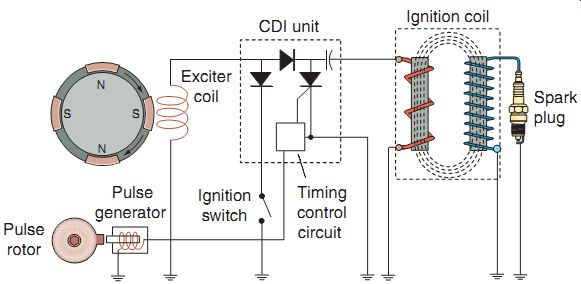
FIG. 21 A typical capacitor discharge ignition (CDI) system.
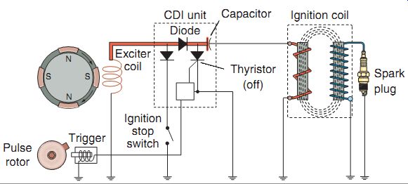
FIG. 22 The capacitor in the CDI unit stores the diode-rectified DC until
it's needed to fire the spark plug.
Capacitor Discharge Ignition Systems
The electronic ignition system most often used in small power equipment engines is the CDI system. The basic components of a capacitor discharge ignition (CDI) system may be con figured in several ways. Although various CDI systems may have different arrangements of wiring and parts, they all operate in much the same way.
FIG. 21 shows how the components of a CDI system are arranged in a typical power equipment engine. Note that the CDI system contains two coils (windings) that are triggered by magnets in the flywheel/rotor or AC generator. The larger coil is called the charging or exciter coil, and the smaller coil is called the trigger coil. The trigger coil controls the timing of the ignition spark and essentially replaces the breaker points.

FIG. 23 A low-voltage signal induced in the trigger coil activates the
electronic switch (SCR) in the CDI unit. This completes the primary circuit,
which enables the capacitor to discharge through the primary winding of the
ignition coil.
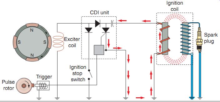
FIG. 24 The transformer action of the ignition coil causes a high voltage
to be induced in the secondary of the ignition coil, which fires the spark
plug.
As the flywheel/rotor rotates past the exciter coil, the AC produced by the exciter winding is rectified (changed to DC) by the diode in the CDI unit. The capacitor in the CDI unit stores this energy until it's needed to fire the spark plug (FIG. 22). As the flywheel/rotor magnet rotates past the trigger coil, a low-voltage signal is in the trigger coil, which activates the electronic switch (SCR) in the CDI unit ( FIG. 23). The SCR acts as the power source to the primary side of the circuit. This completes the primary circuit, to allow the energy stored by the capacitor to pass through the primary winding of the ignition coil. The transformer action of the ignition coil causes a high voltage to be induced in the secondary of the ignition coil, which fires the spark plug (FIG. 24).
Another type of CDI ignition system found in some power equipment engines is one that uses DC from a battery as its source of volt age, with a voltage booster placed in the CDI unit, instead of the AC generator and an exciter coil (FIG. 25). The voltage booster amplifies the battery voltage to over 200 volts. This type of CDI system uses the same components we've just discussed and operates in the same fashion.
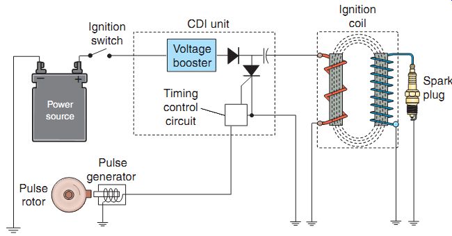
FIG. 25 A simplified DC CDI system.
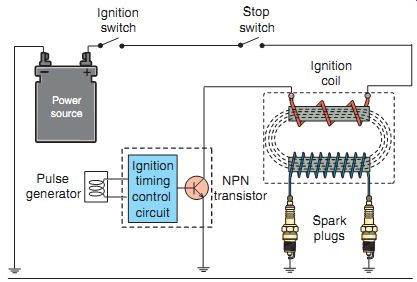
FIG. 26 A transistorized ignition system.
Transistorized Ignition Systems
Not popular but still used in some power equipment engines, the transistorized ignition system (FIG. 26) operates by controlling the flow of electricity to the primary coil of the ignition. With this type of ignition system, transistors are contained within the ICM and are used to supply electricity to the primary coil.
When the voltage level in the primary reaches a certain level, a second transistor turns off the first transistor. This causes the magnetic field around the primary coil to collapse, which creates the high voltage across the secondary coil.
The high voltage is then discharged across the spark plug.
Digitally Controlled Transistorized Ignition Systems
The digitally controlled transistorized ignition system is a type of transistorized point less ignition (TPI) that's found in most power equipment engine applications today. The electronic components of a digitally controlled ignition system are contained in one unit that can be mounted directly to the power equipment engine. In this type of system, a transistor and a microcomputer are used to perform the trigger switching function.
The digitally controlled transistorized ignition system digitally controls ignition timing using a microcomputer inside the ICM ( FIG. 27). The microcomputer calculates the ideal ignition timing at all engine speeds.
The microcomputer also has a fail-safe mechanism, which cuts off power to the ignition coil in case the ignition timing becomes abnormal.
These ignition systems can also have built-in rev-limiters.
The generator rotor has projections, known as reluctors, that rotate past the ignition pulse generator, producing electronic pulses. The pulses are sent to the ICM. The engine rpm and crankshaft position of the cylinder are detected by the relative positions of the projections that are located on the rotor.
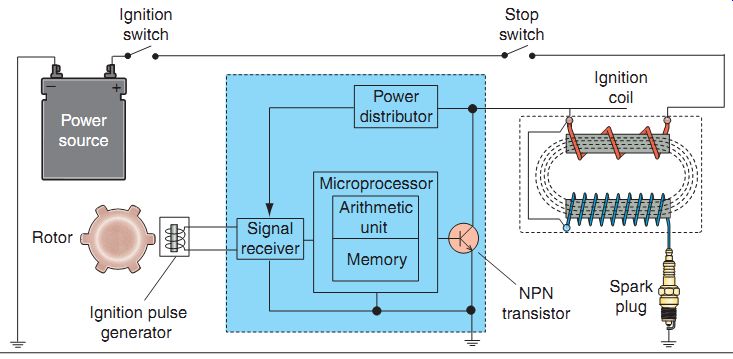
FIG. 27 A digitally controlled transistorized ignition system.
The ICM consists of a power distributor, a signal receiver, and a microcomputer. The power distributor distributes battery voltage to the ICM when the ignition switch is turned to the On position and the engine stop switch is in the Run position. The signal receiver uses the electronic pulse from the ignition pulse generator and converts the pulse signal to a digital signal. The digital signal is sent to the microcomputer, which has a memory unit and an arithmetic unit. The memory unit stores predetermined characteristics of the timing for different engine speeds and crankshaft positions. It then deter mines when to turn the transistor on and off to achieve the correct spark plug firing time.
When the transistor is turned on, the primary winding of the ignition coil is fully energized. The microcomputer turns the transistor off when it's time to fire the spark plug. This collapses the magnetic field and induces a high voltage in the ignition coil secondary winding to fire the spark plug.
Visually, both the standard TPI system and the digital TPI system look similar. The primary visual difference between these two popular ignition systems is the ignition pulse generator rotor. When used on a standard TPI, the pulse generator rotor has only one reluctor to signal the pulse generator. On the digital TPI sys tem, there are several reluctors to "inform" the microcomputer of the engine's rpm and crank shaft position.
ELECTRIC STARTER SYSTEMS
Electric starting systems found in power equipment engines use a DC motor that converts the battery's electrical energy into mechanical energy, which turns the engine's crankshaft quick enough to start the engine. Because the cur rent required for a starting system is very high, a starter solenoid (also known as an electro magnetic switch) and heavy-gauge electrical leads are used to make the connection between the battery and starter motor. When the starter motor electrical circuit is completed, it engages a starter drive clutch that in turn engages, directly or indirectly, the engine's crankshaft. Reduction gears between the starter motor and starter clutch are used to multiply the starter motor's torque output. There are numerous safety features found in electric starting circuits to ensure that the engine can't be started under certain circumstances, such as not being on the seat of the implement or having to place pressure on the brake and/or clutch pedal (FIG. 28).
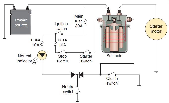
FIG. 28 A basic electric starting circuit.
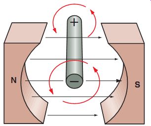
FIG. 29 A current-carrying conductor placed in a magnetic field causes
motion.
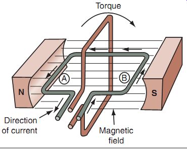
FIG. 30 A loop of current-carrying conductor placed in a magnetic field
causes a rotary motion.
DC Motor Operating Principle
The electric starter motor uses the operating principle of the DC motor. As we've discussed in Sections 13 and 14, when an electric current flows through a conductor wire, magnetic lines of force encircle the wire. If the current - carrying wire is placed between the north and south poles of a magnet, a reaction occurs between the magnetic field encircling the wire and the magnetic field between the magnets.
From FIG. 29, we can see that the magnetic lines of force (of the current-carrying wire and of the magnet) reinforce each other below the wire, where they run in the same direction, and tend to cancel each other out above the wire, where they run in opposite directions. This causes the wire to be forced upward. The cur rent-carrying wire is always pushed away from the side having the stronger magnetic field. If the electrical current through the wire was reversed, just the opposite reaction would occur, and the wire would be forced downward.
If a loop of current-carrying wire is placed between the north and south poles of a mag net, as seen in FIG. 30, the direction of the current flow (and therefore the direction of the magnetic field encircling the wire) in the loop at A is opposite to the direction of current flow (and magnetic field) in the other side of the loop at B. Therefore, Side A of the loop is forced upward while Side B is forced downward.
This causes the black-colored loop in the figure to rotate in a clockwise direction until it stands perpendicular to the lines of magnetic force between the magnetic poles.
If both the brown and grey wires in FIG. 30 are fixed so that they rotate together, the grey-colored wire would be in the horizontal position when the brown-colored wire is vertical. Now, if we pass a current through the grey wire, as we did for the brown wire when it was in the horizontal position, the grey wire will be forced to turn in the same (clockwise) direction.
This continues the rotary motion of the wires.
As the grey wire is turned to the vertical position, the brown wire is returned to the horizontal position. However, to make the motor continue to rotate in the same direction, the cur rent in the brown wire must now be reversed.
The reversal of current flow is accomplished by a commutator-and-brush arrangement, as shown in FIG. 31. The battery is connected to carbon brushes, which slide against commutator segments. Each commutator segment is connected to one end of a wire loop. The commutator segments rotate with the wire loops. As the segments turn, each brush slides from one commutator segment to the next. The direction of current flowing through each wire loop is reversed when the brushes contact opposite commutator segments, allowing the loop to continue rotating as long as there's battery current being sent to the brushes.
The DC motor we've described has been greatly simplified to illustrate the basic principles of the DC motor. In an actual DC motor, many loops of wire, called armature windings, are used to make the DC motor run more smoothly and develop more power. Also, some starter motors use electromagnets rather than the permanent magnets shown in our simple illustration.
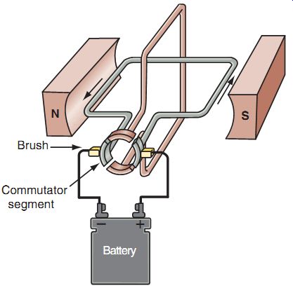
FIG. 31 The operation of a commutator and brushes in a DC motor.
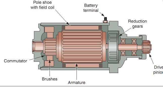
FIG. 32 An electric starter motor.
Starter Motor Construction
FIG. 32 shows a cutaway of a typical starter motor. The motor contains coils of wire wound around a laminated-iron armature core.
At one end of the armature, there are copper commutator segments, which directly correspond to the number of armature coils of wire.
Each of the commutator segments is insulated from the others. The armature coils are spaced in such a manner that, for any position of the armature, there will be coils near the poles of the field magnets. This makes the torque both continuous and strong. Electromagnets are used in many starter motors instead of permanent magnets because they can be made to provide a stronger magnetic field.
Brushes are made out of carbon, because of which they have a long service life and cause minimum commutator wear. Springs are used to hold the brushes firmly against the commutator (FIG. 33). The brushes and commutator connect the field coil windings with the armature windings in series. Therefore, any increase in cur rent strengthens the magnetism of both the field and the armature. DC motors produce high starting torque, which is necessary in a starter motor.
The brushes have a specification for length, as they can wear with time (FIG. 34).
The armature shaft is connected to a gear reduction system, which multiplies the motor's torque. This enables the starter to turn the engine over easily under compression. The gear reduction system may be contained in the engine crankcase or built into the starter motor housing, depending on the engine design.
Starter Solenoids
A starter motor can draw in excess of 120 amperes of current when cranking the engine.
A heavy electrical cable and a heavy-duty switch are required to properly handle this high current flow. It would seem obvious that it wouldn't be practical to run heavy cables up to the handle bar and install a large, heavy-duty switch there.
Therefore, instead, a small key or push-button switch on the implement activates an electro magnetic starter solenoid switch, as shown in FIG. 35. The starter solenoid connects the battery to the starter motor. You'll generally find the solenoid mounted near the battery.
When the main switch is turned on and the starter button is pressed, the starter solenoid primary circuit is completed. DC flows from the battery through an electromagnet in the solenoid. The electromagnet pushes the plunger into contact with the starter switch terminals, completing the circuit between the battery and the starter motor.
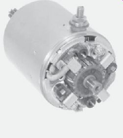
FIG. 33 The end cap of this starter motor has been removed to show its
brushes, brush springs, and commutator.
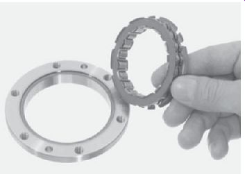
FIG. 36 A one-way starter clutch.
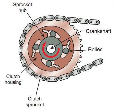
FIG. 37 A typical chain-drive starter clutch.
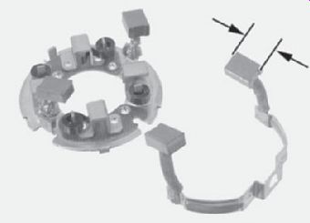
FIG. 34 Because contact brushes on starter motors are made out of carbon
and wear with time, manufacturers have a length specification to measure wear.
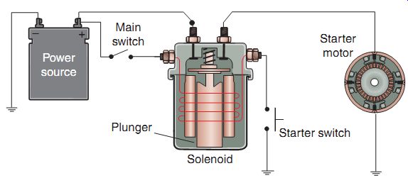
FIG. 35 An electromagnetic starter switch and solenoid.
Starter Clutches
The starter clutch is a mechanism that allows the starter motor to engage only while the starter motor is operating to start the engine.
Starter clutches are also known as sprag clutches ( FIG. 36).
When the engine starts, the engine's increased speed automatically disengages the starter motor. FIG. 37 shows a starter clutch. This particular starter clutch would be installed on the crankshaft and is chain driven.
The starter-clutch housing is attached to the engine's crankshaft. Starter engagement is achieved by locking the gears of the starter motor to those of the starter-clutch housing, and disengagement is achieved by unlocking these parts. Spring-loaded rollers in the clutch housing perform the locking and unlocking functions.
The rollers ride on ramps within the starter clutch housing. When extended, the rollers wedge the hub tightly against the clutch housing. When the rollers are retracted, the sprocket hub and clutch housing are no longer locked together.
Summary
The ignition system has three main functions. First, it must generate an electrical spark that has enough heat to ignite the air-fuel mixture in the combustion chamber. Second, it must maintain that spark long enough to allow for the combustion of all the air and fuel in the cylinder. Lastly, it must deliver a spark to the cylinder so combustion can begin at the right time during each compression stroke of the piston.
The main components of an ignition system are the power source, ignition switch, ignition coil, spark plug, triggering switch, and stop switch.
All ignition systems use a primary coil and a secondary coil. The current in the primary coil induces a relatively large voltage in the secondary, to create a high output voltage to the spark plug.
There are two general types of ignition systems: breaker point and electronic ignition. There are four types of breaker point systems: high-tension magneto, low-tension magneto, energy transfer, and battery point.
There are three basic types of electronic ignition systems: capacitive discharge, transistorized, and digitally controlled transistorized systems.
Electric starting systems found in power equipment engines use a DC motor to transform the battery's electrical energy into mechanical energy, which turns the engine's crankshaft quick enough to start the engine.
The current required for a starting system is very high. Therefore, a starter solenoid and heavy-gauge electrical leads are used to make the connection between the battery and starter motor.
QUIZ
1. The side electrode of a spark plug is also called the __.
2. A spark plug that can easily transfer combustion heat from the firing end to the shell and then to the cylinder head is called a plug.
3. Correct spark plug is essential for achieving optimum engine performance and long plug life.
4. The winding of an ignition coil uses relatively few turns of heavy copper wire in relation to the winding.
5. A capacitor discharge ignition system has fewer moving parts than an energy-transfer ignition system. (True/False)
6. The power source in a power equipment engine ignition system is connected directly to the secondary winding of the ignition coil. (True/False)
7. The electromagnetic switch that's used to activate the starter motor is known as a __.
8. Electric starters are used to transform the battery's electrical energy into energy to turn over the engine's crankshaft.
9. In a CDI ignition system, which one of the following components stores the energy to fire the spark plug?
a. Capacitor c. Charging coil
b. Diode d. SCR
10. The function of the condenser in a breaker points ignition system is to
a. advance the engine timing at high rpm.
b. induce a voltage in the primary coil.
c. delay the opening of the points.
d. prevent electricity from arcing across the points.
11. The length of the metal threads at the end of a spark plug is called the
a. ground. c. insulator.
b. reach. d. shell.
12. Which of the following is an ignition component requiring no adjustment?
a. Contact breaker points
b. Mechanical advancer
c. Electronic advancer
d. Voltage regulator
13. The flywheel/rotor and the crankshaft are held together in alignment by the
a. armature coil.
b. woodruff key.
c. cylinder head.
d. magneto.
14. Which of the following statements about the ignition coil in a power equipment engine ignition system is correct?
a. The coil will be found only in an ignition system that's powered by a magneto.
b. The coil's iron core is called the primary winding.
c. The secondary winding is connected to the spark plug wire.
d. The secondary winding contains fewer coils of wire than the primary winding.
15. An electric starter system uses a to carry the high current from the battery to the starter.
a. condenser.
b. magneto.
c. capacitor.
d. solenoid.