AMAZON multi-meters discounts AMAZON oscilloscope discounts
Goals:
- Understand the importance of proper safety procedures when working with electrical systems
- Explain the two basic theories of electricity
- List the types of electrical circuits
- Explain the terms voltage, current, and resistance
- Calculate voltage, current, and resistance using Ohm's law
- Describe how to use a multi-meter to measure voltage, resistance, and current
- Understand the term schematic and understand how to read a simple wiring diagram
-------------
INTRODUCTION
This section, the first of three that will concentrate on the subject of electricity, will show you the basics of electricity, where electricity comes from, and how we measure electricity. In Sections 13 and 14, we'll discuss charging systems, ignition systems, and other electrical circuits found in power equipment engines.
Since electricity can't normally be seen, many technicians know little about it and are somewhat afraid of it. Electricity isn't a difficult subject to master as long as you under stand the basics of how electricity works. It's true that you don't have to be an engineer with a background in the theory of electrical systems to competently service the electrical systems in modern power equipment engines. But of course, for you to understand why some thing isn't functioning properly, you must first know how it works.
The technician who understands how electrical systems produce, conduct, store, and use electrical energy will find it easier to locate and correct problems in these systems. Therefore, in this section, we'll discuss the fundamentals of electricity, including the terms used in this field, and cover the primary tool used to measure various electrical components.
You may be wondering what exactly is electricity? Although there are many answers to this question, we'll state that, for our purpose of working on power equipment engine electrical systems, electricity is a natural force produced by the movement of electrons.
Although you should understand the basic theory and facts presented in this section, you won't be expected to memorize complex electricity formulas and theories and become an expert at electrical systems. In fact, I've tried very hard to make learning of electricity and electrical systems as easy as possible. Only the simplest terms have been used to help you to understand this interesting subject area of power equipment engine repair.
The electrical system is perhaps the most important support system used with power equipment engines. Without electricity, an engine would not run. Electricity provides the needed spark for combustion as well as the power required for electric starting, lights, instrumentation, and many other accessories found on various types of power equipment.
Advances in the field of electronics have brought new technologies to the power equipment engine industry that make them more efficient. Today's technicians need to understand basic electrical circuits before they can diagnose and service these new technologies. Although test equipment used on modern engines simplify a technician's job, understanding electrical principles, circuit design, and testing procedures continue to be necessary for a successful modern power equipment engine technician.
SAFETY PRECAUTIONS WITH ELECTRICITY
Electrical devices and circuits can be dangerous. Safe practices are necessary to prevent shock, fires, explosions, mechanical damage, and injuries resulting from careless or improper use of tools.
Perhaps the greatest hazard of working with electricity is the electrical shock. Electricity affects the body by overriding brain impulses and contracting muscles. Therefore, a current in excess of 10 milliamperes running through the human body can make it difficult or impossible for you to let go of "live" conductor. Current over 100 milliamperes can be fatal. And how much is a milliampere? One thousandth of an ampere! When dry, your skin can have approximately one thousand times more resistance to the flow of electricity than when it's wet; this resistance would be in the vicinity of several hundred thou sand ohms. When moist or cut, however, the skin's resistance may become as low as several hundred ohms. In this condition, even so-called safe voltages of 30 or 40 volts might produce a fatal shock. Naturally, the danger of harmful or fatal shock increases directly as the voltage increases. You should be cautious, even with low voltages. Never assume a circuit is dead, even though the switch is in the off position.
Safe electrical practices will protect you and those around you. Study, memorize, and adhere to the following rules.
Don't work when you're tired or taking medicine that makes you drowsy.
Don't work in poorly lighted areas. Don't work in damp areas. Use approved tools, equipment, and protective devices.
Don't work if you or your clothes are wet. Remove all rings, bracelets, and similar metal items.
Never assume that a circuit is off. Check it with a device or equipment that you're sure is operating properly.
Don't tamper with safety devices. Never disconnect an interlock switch to bypass it.
Keep your tools and equipment in good condition. Use the correct tool for the job.
Verify that capacitors have discharged. Some capacitors may store a lethal electrical charge for a long time.
Don't remove equipment grounds. Verify that all grounds are intact.
Don't use adapters that bypass ground connections.
Use only an approved fire extinguisher. Water can conduct electric current and increase the hazards and risk of damage. Carbon dioxide (CO2) and certain halogenated extinguishers are preferred for most electrical fires. Foam types may also be used in some cases.
Follow directions when using solvents and other chemicals. They may explode, ignite, or damage electrical circuits.
Certain electronic components affect the safe operation of equipment. Always use correct replacement parts.
Use protective clothing and safety glasses. Don't attempt to work on complex equipment or circuits without proper training.
There may be many hidden dangers.
Some of the best safety information for electrical and electronic equipment is the literature prepared by the manufacturer. Find it, read it, and use it! When possible, keep one hand in your pocket while working with electricity. This reduces the possibility of your body providing an electrical path through the heart.
Any of these rules could be expanded. As your study progresses, you'll learn many of the details concerning proper procedures. Learn them well because they're the most important information available. Remember, always practice safety; your life depends on it.
BASICS OF ELECTRICITY
As mentioned previously, perhaps the main reason that most people find it difficult to understand electricity is that they can't actually see it. By actually knowing what electricity is and what it's not, one can easily understand it. One thing is for sure: electricity is not magic! It's something that either takes place or can take place in everything around us. It not only pro vides power for the lights and refrigerator in your house but also is the basis for the communications between your brain and your eyes as you read this sentence! Electricity can't be seen, because it results from the movement of extremely small objects that move at close to the speed of light (which is 186,000 miles per second!) However, although electricity can't be seen, its effects can be seen, felt, heard, and even smelled. One of the most common displays of electricity is a lightning bolt. Lightning is electricity, albeit a large amount of electricity. In fact, the power of lightning is incredible. Using electrical power in much smaller amounts to perform some work is the working basis for a power equipment engine's electrical system.
The typical power equipment engine electrical system has many paths through which electricity can flow. The four major electrical systems found are Starting systems, which are used on many power equipment engines to rotate the crank shaft for the purpose of starting the engine Ignition systems, which provide a high-energy spark to ignite the air-fuel mixture inside the engine's combustion chamber Lighting systems, which are used to power the lights as well as operate other electrical equipment on the machine Charging systems, which are used to produce the electricity to recharge a battery that is used to store electricity There are also many other electrical sub systems.
Let's take a closer look at electricity, starting with some basic theories in electricity, a basic electricity storage container, and a simple circuit.
Electricity Theories
There are two basic theories of electricity. It's important that you understand the two theories as well as the difference between them.
Conventional Theory of Electricity
The conventional theory of electricity states that electric current flows from the positive terminal of the voltage source, through the circuit, to the negative terminal. Simply stated, this theory states that electricity flows from positive to negative.
It's not known with certainty as to who came up with the conventional theory of electricity. In the mid-1700s, Ben Franklin studied electricity and is credited with the first use of the terms battery, positive, and negative, to describe the terminals of a battery. Many of the characteristics of electricity that we take for granted today were not known in Franklin's time. It was thought, per the conventional theory, that electric current flowed from the positive terminal of the voltage source, through the circuit, to the negative terminal.
You should know that the conventional theory of electricity is generally used in the explanation of electrical circuits in the power equipment engine industry.
The Electron Theory
One hundred and fifty years after the conventional theory was proposed, a group of scientists developed the electron theory of electricity.
Like most new ideas, the electron theory of electricity was not accepted at first. In many industries, including ours, it's still not in wide use. However, the electron theory is the basis of modern electronics.
The electron theory of electricity states that electricity is the flow of electrons from the negative terminal of a source through a conductor, completing the circuit back to the positive terminal of the source. Simply stated, this theory states that electricity flows from negative to the positive.
Scientists now generally accept as true the electron theory concerning the nature of electricity.

FIG. 1 Atoms are composed of electrons, protons, and neutrons.
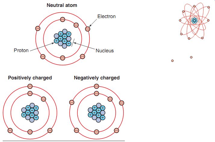
FIG. 2 A neutral atom has an equal number of protons and electrons. A
positively charged atom has more protons than electrons. A negatively charged
atom has more electrons than protons.
Atoms
All matter is composed of molecules, and each molecule contains two or more atoms. Atoms, in turn, are made up of neutrons, protons, and electrons (FIG. 1). It's the arrangement of these particles that makes materials to exist in the form of liquids, solids, and gases.
The core of the atom, called the nucleus, contains protons and neutrons. Protons have a positive electrical charge and neutrons are neutral, meaning that they have no electrical charge. Electrons have a negative charge and rotate around the nucleus of the atom. Atoms normally have an equal number of protons and electrons and therefore an equal number of positive and negative electrical charges. These [...]
of electrons from you to the metal caused the small shock that you felt.
Thus, you can see that it's not impossible to get electrons moving from one place to another. However, it's easier to get electrons moving in some materials than in others. The structure of an individual atom determines how easily an electron can be removed from it. For example, in FIG. 3, you can see from the structure of the copper atom that the outermost electron can easily be dislodged from its orbit. Therefore, it's easy to get a flow of electricity moving in copper.
Any material in which electrons can move freely is called an electrical conductor. Copper, silver, gold, and other metals are good electrical conductors. In fact, silver and gold are better electrical conductors than copper, but because silver and gold are so expensive, they generally are not used to make electrical wires in power equipment engines. Materials, such as plastic, nylon, and ceramic, that have electrons tightly bonded to the nucleus offer resistance to the flow of electricity and are classified as insulators.
The Battery
We'll now discuss the battery, which is a storage device for electricity used on many types of power equipment. We'll also discuss the basics of batteries here. They're discussed in more detail in Section 14.
Note that batteries have two ends. The end of the battery that's labeled with a minus sign (-) is called the negative terminal. The opposite end of the battery that's labeled with a plus sign (+) is called the positive terminal. The negative terminal of the battery has a negative charge, as it contains too many electrons. The positive terminal of the battery has a positive charge, as it contains too few electrons.
The negative and positive charges in a battery are produced by a simple chemical reaction. The battery terminals, or electrodes, are two strips of lead. Each electrode is made from a different type of lead. When these strips of metal are placed into an electrolyte solution, a chemical reaction occurs. An electrolyte is a chemical compound which, when molten or dissolved in certain solvents (usually water), conducts an electric current. As a result of this reaction, a negative charge forms on one electrode and a positive charge forms on the other electrode.
You've probably heard the phrase opposites attract. This phrase really holds true with electricity! Opposing electrical charges (positive and negative) strongly attract each other and try to balance each other out. Because of this attraction, whenever too many electrons are in one place, the electrons will try to move to a place where there are fewer electrons. This is the basic operating principle of a battery. The negative terminal of a battery has a high concentration of electrons, whereas the positive terminal has very few electrons. So, the electrons at the negative battery terminal will be drawn toward the positive battery terminal. But to actually move from the negative terminal to the positive terminal, the electrons need a path to follow. We can create a path for the electrons by connecting a conductor and a load between the battery terminals. By connecting these pieces, we actually build a circuit.
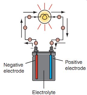
FIG. 4 Shown is a chemical reaction between the electrodes and the electrolyte
solution. This reaction produces an electrical charge on each of the electrodes.
In the simple circuit shown in FIG. 4, electrons flow from the negative battery terminal to the positive terminal through the conductors and the lightbulb. Note that the flow of electricity produced by the battery will continue as long as the chemical reaction in the battery keeps up. After some time, the chemical reaction in the battery will stop, and the battery will stop functioning. At that point, the battery will need to be recharged or replaced. This is why power equipments that use batteries also have charging systems.
Capacitors
Capacitors, also known as condensers, are also used to store electricity. In an electrical circuit using a capacitor, the capacitor charge usually equals the circuit voltage. If the circuit voltage falls or if the circuit is open, the capacitor will release its charge. In a circuit where short bursts of volt age are needed, capacitors are very useful. Section 15 provides an example of capacitor usage in power equipment engine ignition systems.
Circuits
There are three requirements to complete a simple circuit: a power source, a conductor, and a load. A power source is simply a source of electrical power. The power source in an electrical circuit in a power equipment engine is generally a battery. Conductors are the wires that carry the electricity. A load is any device, such as a lightbulb, that we want to run with electricity. In order to use electrons to perform useful work, we've connected a lightbulb to the circuit, which is our load (FIG. 5).
We may choose to allow a circuit to be closed or open. In a closed circuit, when the switch is turned on, electrical power from the power source flows through an unbroken path to the load, flows through the load, and then returns to the power source. In other words, when we turn the switch on, electrons from the negative battery terminal travel to the positive battery terminal. This flow of electrons through a circuit is called electric current. In contrast, in an open circuit, the switch is turned off, which breaks the path of the circuit so that power doesn't reach the load. FIG. 6 shows a simple lighting circuit. The power source in this circuit is a battery, the conductors are copper wires, and the load is a lightbulb. FIG. 6a shows an open switch (i.e., the switch is in the off position). The electrical circuit is therefore open, and power can't flow through the wires to reach the bulb.
FIG. 6b shows a closed switch (i.e., the switch is in the on position). This circuit is complete, and electricity flows through the wires to reach the bulb, causing the filament to heat up and glow. The simple circuit that we've just described is known as a series circuit.
You should note that all electrical systems, no matter how large, can be broken down to simple circuits similar to the circuit that we've just discussed.
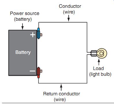
FIG. 5 There are three requirements to complete a circuit: a power source,
a conductor, and a load.
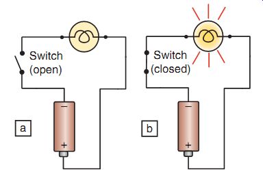
FIG. 6 A simple circuit: In (a) the circuit is open; in (b) the circuit
is closed.
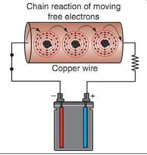
FIG. 7 The enlarged portion shows you how electrons flow through a wire.
A free electron from the battery enters the wire. The free electron then creates
a chain reaction within the wire, where free electrons bump other electrons
from the outer shell of the atoms. The remaining free electrons are drawn to
the positive side of the battery, completing the circuit.
Electron Flow in a Circuit
Let's take a closer look at how electrons flow in an electrical circuit. FIG. 7 shows a simple series circuit, in which a copper wire is connected to a battery. One section of the copper wire is enlarged so that you can see how electrons flow through it.
In the figure, the circuit is closed, and the electrons from the negative terminal are drawn to the positive terminal. Remember that the outermost electron in each copper atom is easily dislodged from its orbit. An electron is drawn from the negative battery terminal into the cop per conductor wire. This electron then collides with a free electron in a copper atom, bumping a free electron and taking its place. The displaced free electron moves to a neighboring copper atom, bumps a free electron out of the copper atom's orbit, and takes its place. As this chain reaction continues, free electrons bump their neighboring electrons out of their orbits, taking their place. This chain reaction of moving electrons constitutes electric current.
In reality, of course, atoms are much too small to see; so we can't follow the movement of just one electron through a wire. Many millions of copper atoms make up a single strand of wire. When a circuit is closed, millions of electrons move through the wire at the same time, at a high speed. The greater the number of electrons moving through a circuit, the stronger the current in the circuit.
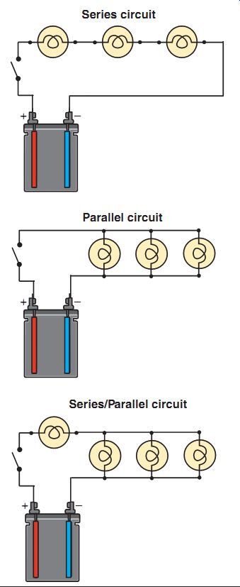
FIG. 8 A series, parallel, and series/parallel circuit.
Types of Circuits
There are many types of circuits used in electrical systems (FIG. 8). We've already talked about one simple electrical circuit, the series circuit. A series circuit is a circuit that has only one path for electrons back to the source of power. In a series circuit, if one lightbulb burns out, the whole circuit shuts down since there's no path for electricity to continue to flow. A
parallel circuit is a circuit that has more than one path for electrons back to the source of power. In a parallel circuit, if a lightbulb burns out, it won't have any effect on the other bulbs in the circuit because each of them functions as separate return path for electrons to the source of power. A popular type of circuit that you'll find in power equipment engines is a combination of the series and the parallel circuit, called the series/parallel circuit. The series/parallel circuit contains a load in series and a parallel load in the same circuit.
FIG. 9 Electric current flowing through a wire can be compared to water flowing through a pipe. When Tanks A and B are connected, water will flow from Tank A to Tank B. This flow is the result of a pressure difference, which is similar to the pressure difference found between voltages at different points in a circuit.
If the connecting pipe is small, less water flows compared to water flow in the larger pipe. This is analogous to electrical resistance.
Unwanted Circuit Conditions
There are several possible conditions in an electrical circuit that have an adverse effect on electrical systems. These circuit conditions are opens, shorts, and grounds.
As you already know, an open circuit is a circuit in which the path for current to flow is incomplete. An example of an open circuit, which is generally an unwanted circuit condition, is a broken wire or a blown lightbulb. A short circuit is a circuit that has developed a path for electricity to flow to the source of power before it reaches the load. A short circuit will blow fuses in the circuit as well as damage wires and components in the electrical system. A grounded
circuit is a circuit that allows power to flow back to the source after the load, but before the means of control, that is, a component used to control current or voltage in a circuit (such as a transistor switch). An example of a grounded circuit would be a horn that blows without pushing the horn button.
Properties of Electricity
Confused yet? If so, don't worry, you'll under stand! Let's take a look at the properties of electricity in a way that may make all of this easier to comprehend. Electric current flowing through a wire can be compared to water flowing through a pipe (FIG. 9). The laws governing electric circuits are easily explained by this analogy.
Voltage
Water pressure is measured in pounds per square inch, while electrical pressure is measured in volts. When the two water tanks in our illustration, A and B, are connected, water flows from Tank A to Tank B.
This flow is the result of a height difference between the two tanks. Water will flow through the pipe from the full tank to the empty tank until the water level is even in both tanks. The pressure from the weight of water in the full tank will naturally cause the water to flow. A valve could be installed to open or close the water passage and another could be used to decrease the flow or increase it as desired.
Similarly, electrical current will flow through a wire because of electrical "pressure" created by a battery or an alternator. The electrical pres sure is measured as voltage (V).
Resistance
Water will have a lower rate of flow through a smaller or longer pipe because of the increased resistance. Similarly, electrical current will have a lower rate of flow through a smaller or longer conductor such as wire. Partially closing off the flow from the pipe decreases water flow. Similarly, a load or resistance in an electrical circuit, such as a lightbulb, decreases voltage.
UNITS OF ELECTRICITY
We just discussed a couple of the key electrical units of measurement, voltage and resistance.
Throughout this section, you'll learn terms that are used in connection with electrical systems, and learn some basic formulas. There are three basic units of measurement used to measure electricity: current, voltage, and resistance.
Each unit of measurement is named after a famous experimenter in electricity: The ampere after the Frenchman Andre M. Ampere, the volt after the Italian Alessandro Volta, and the ohm after the German Georg Simon Ohm.
Amperes (Current)
As you've already learned, when a complete conducting path is present between two opposing electrical charges, electrons flow between the two points. Current is the rate of flow of electrons through a conductor. Current is measured in units called amperes, also called amps, which is often abbreviated with the letter "A." For instance, "3 amperes" would be abbreviated to "3 A." In electrical work, electrical drawings, diagrams, and mathematical formulas, the letter I is used to represent current. Small amounts of current can be measured in milliamperes, which is abbreviated to "mA." One milliampere of cur rent is equal to one-thousandth of an ampere, or 0.001 A of current.
Volts (Voltage)
Now, let's look at the electrical term voltage. Remember that in a battery, one terminal has a negative charge and the other terminal has a positive charge. Whenever a positive charge and a negative charge are positioned close to each other, a force is produced between the two charges. This force is called electrical potential, which is simply the difference in electrical charge between the two opposing terminals. Electrical potential can also be thought of as the amount of electrical pressure in an electrical system. The bigger the difference between the two opposing charges, the greater the electrical potential will be. Voltage is a measurement of the amount of electrical potential in a circuit. Voltage is measured in units called volts, which is often abbreviated to "V." For instance, 12 volts would be abbreviated "12 V." In electrical diagrams and mathematical formulas, voltage is usually represented by the letter E.
Ohms (Resistance)
The last electrical term we'll look at is called resistance. Resistance is a force of opposition that works against the flow of electrical current in a circuit. You've already seen that current flows easily through copper wires in a circuit. However, frayed wires, corroded connections, and other obstructions will reduce the flow of electrons through a circuit, that is, the circuit will resist the flow of current through it. When a lot of resistance is present in a circuit, more voltage is needed to increase the flow of electrons moving through the circuit. Resistance is measured in units called ohms, which is often abbreviated with the Greek letter omega, represented by the symbol "?." In electrical diagrams and mathematical formulas, the letter R is usually used to represent resistance. Power equipment engine service manuals often provide electrical specifications in ohms. A service manual may tell you, for example, that the resistance you should be able to measure between the leads on a charging system stator should be 0.2 ohm. Note that we'll discuss charging systems, their components, specifications, and how to measure circuit quantities in more detail in Section 14.
Ohm's Law
Although it seems simple to guess why the letter R is used for resistance, you must be wondering why the abbreviation for voltage is the letter E and that for current is I, right? Well, the letter I for current represents the intensity of electron flow, and the letter E represents electro motive force.
There is an important law relating the values of resistance, current, and voltage in a circuit. The amount of current flowing through a completed circuit is directly proportional to the voltage applied across the conductor. This relation between resistance, current, and voltage is known as Ohm's law.
Ohm's law states that a resistance of 1 ohm (1 ?) permits a current flow of 1 ampere (1 A) in a circuit that has a source voltage of 1 volt (1 V). This rule can be applied to any voltage, resistance value, or amperage. If you have any two of the values, the third can be determined by using Ohm's law.
This relation, known as Ohm's law, is expressed with the mathematical formula:
Voltage (E) = Current (I) × resistance (R)
Two other useful variations of the Ohm's law equations are:
Current (I) = Voltage (E) divided by resistance (R)
Resistance (R) = Voltage (E) divided by current (I)
To understand how to use these equations, consider FIG. 10 and then the following example. As you can see in the illustration, if you cover the unknown quantity with your finger, you can determine the unknown by using the remaining pieces of the formula.
If you have a circuit that draws 3 amperes of current from a 12-volt battery, how much resistance is in the circuit? To solve this equation, simply install the known measurements in the formula as follows:
Resistance (R) = 12 (E) divided by 3 (I)
The answer is 4 ohms.
Ohm's law yields a useful formula that you should know. The Ohm's law formula is used frequently to analyze circuits and troubleshoot problem areas. By using these three given variations of the Ohm's law formula, it's easy to find the proper voltage, resistance, and current values for any circuit.
You should note that as the resistance in a circuit increases, the current decreases. Conversely, if the resistance in a circuit decreases, the cur rent increases. All circuits are designed to carry a particular amount of current. In fact, most circuits are protected by fuses that are rated at an amperage value that's just slightly higher than the current value of the circuit. Thus, if a problem develops in a circuit, the circuit will draw too much current from the battery and the fuse's elements will melt (the fuse will blow), creating an open in the circuit. This design prevents any further damage to the electrical circuit.

FIG. 10 An illustration of how Ohm's law works. By covering the unknown
quantity with your finger, you can determine the unknown by using the remaining
pieces of the formula.
Watts (Electrical Power)
When consumers buy electricity, they buy power. The unit of power for electricity is the watt. A simple formula for relating watts to volt age and current is
E R E I
If E is unknown, cover it with a finger and the formula becomes I x R
If I is covered with a finger, the formula reads
If R is covered with a finger, the formula is
Power = voltage × current, or watts = volts × amperes
Thus, if there are 5 amperes going through a resistor, due to a voltage of 200 volts, the power consumed by the resistor is 1000 watts (power = voltage × current = 200 volts × 5 amperes = 1,000 watts).
These measurements, plus an understanding of the nature of electricity, are essential to anyone working with electricity. The user of any electrical test equipment or tools should have some knowledge of the operation and mechanics of the particular circuits and/or the device being tested.
Common Electricity Quantities
Table 1 lists common electrical quantities, their abbreviations, and their multiples in terms of the base unit. You should become familiar with these abbreviations, as you'll see them in different areas of a service manual when working with electrical systems on power equipment engines.

Table 1: Common Electrical Quantities
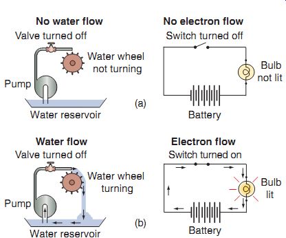
FIG. 11 The basic principles of electricity can be easily visualized
when you compare an electrical circuit to a water flow.
Relation Between Current, Voltage, and Resistance
Let's use the water analogy illustration once again to help you understand better the relation between current, voltage, and resistance in an electrical circuit. We can then compare it to an electrical circuit example (FIG. 11). The following text is a list describing the water analogy.
The water pipes form a path for the water to follow. The water pipes are similar to the conductors in the adjacent electrical system.
The water valve turns the flow of water on and off. The water valve is similar to the switch in the electrical system.
The waterwheel is being operated by the flow of water. The waterwheel is similar to the lightbulb (the load) in the electrical circuit.
The water reservoir (the water source) is similar to the battery (the power source) in the electrical circuit.
The flow of water is similar to the flow of electrons. The amount of flow would be the current.
The water pump is the pushing force that causes the water to flow into the pipes, just what voltage does in the electrical circuit.
The water returns to the pump just as the electrons flow through the ground path back to the battery.
FIG. 11a shows both the water sys tem and the electrical circuit turned off. Both the water valve and the electric switch are in the off position; so no water or current flows.
The waterwheel doesn't turn and the lightbulb doesn't illuminate. FIG. 11b shows the water system and the electrical circuit turned on. Water is pumped out of the reservoir and into the pipes; the water flows through the pipes, turns the waterwheel, and then returns to the reservoir. With the electrical circuit, the switch is turned on. Electric current flows out of the battery through the wires, lights the bulb, and returns to the battery.
In this example, you can think of resistance as being like a blockage or a clog in the water pipe.
If some debris were stuck in the pipe, the flow of water through the pipe would be reduced. Similarly, excessive resistance in an electrical circuit reduces the flow of current through the circuit.
Alternating Current, Direct Current, and Voltage
There are two types of electrical current: direct current and alternating current. It's important that you understand the differences between these two types of current.
Direct Current
Direct current (DC) is the flow of electrons in one direction only. A DC voltage reading is non-varying and on a power equipment engine is usually produced by a battery. For example, if we were to graph a DC voltage of 12 volts over a period of time, the graph would appear as shown in FIG. 12. Whatever the voltage value, a DC voltage remains constant and unchanging over time.
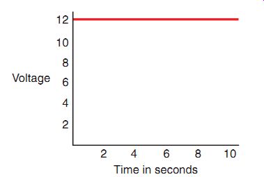
FIG. 12 A DC voltage level remains constant over time.
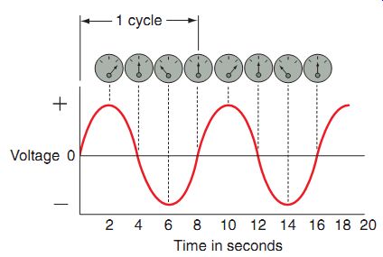
FIG. 13 An AC voltage level changes over time.
Alternating Current
In contrast to DC, alternating current (AC) is the flow of electrons first in one direction and then in the opposite direction. AC reverses direction continually and is produced by an AC voltage source. AC is the type of current found in household electrical systems and wall outlets.
Power equipment engines also produce AC in various ways. (We'll discuss AC in more detail in Section 14.) As you see in FIG. 13, AC starts at zero and then rises to a maximum positive value. At the maximum positive point, the current reverses direction and falls back to zero and continues to drop until it reaches the maxi mum negative value. The current then reverses direction again and rises back to zero. One complete transition of current from zero to the positive peak, down to the negative peak, and back up to zero is called a cycle. These AC cycles repeat continuously as long as the current flows.
As related to power equipment engines, there are three key items needed to produce AC volt age: a magnetic field, a conductor, and motion.
Power equipment engines that don't have a battery or a DC storage device use AC voltage and current for their lighting and ignition systems.
Implements that use a battery use the DC voltage produced by the battery to power the starter, lights, and other accessories. These implements also use AC voltage to keep the charging system working properly, which keeps the battery's voltage level correct. To do this, the AC has to be converted into DC by a process called rectification.
ELECTRICAL METERS AND MEASUREMENTS
Although we can observe the effects of electricity, such as a glowing lightbulb, we can't see the flow of electrons that we call electricity. We can, however, use various meters to observe the action of electric current in a circuit. When you begin working with electrical meters, you'll notice that they use two basic types of readouts, or displays, to present the information: analog and digital. The function of these two types of meters is the same-to display electrical measurements-but the way in which the data is displayed is different.
Analog electrical meter. The display of an analog electrical meter has a movable pointer and a scale (FIG. 14). The meter is usually enclosed in a case and has terminals (test leads), which connect to jacks on the front of the case. In most cases, a red jack indicates a positive terminal and a black jack a negative.
Most analog meters have scales from zero up to some maximum number. Some meters may have zero centered in the middle of the scale, with numbers on the right and the left. Most analog meters have what's called a mechanical zero adjustment. This means that by turning a screwdriver inserted into a small screw on the front of the meter, the pointer can be adjusted so that it's exactly over the zero on the scale. (During this adjustment, the meter shouldn't be connected to any circuit; instead, both leads should touch each other while in the rx1 scale.) The amount of movement of the pointer is called pointer deflection.
Digital electrical meter. The display of a digital electrical meter has a numeric readout (FIG. 15). Like the analog meter, the digital meter is also enclosed in a case and has positive and negative terminals (test leads), which connect to jacks on the front of the case.
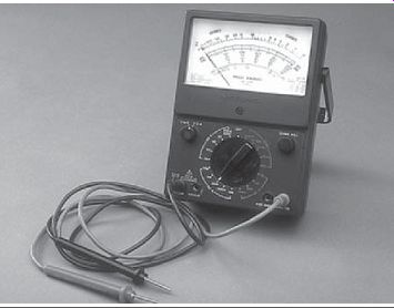
FIG. 14 An analog electrical meter.
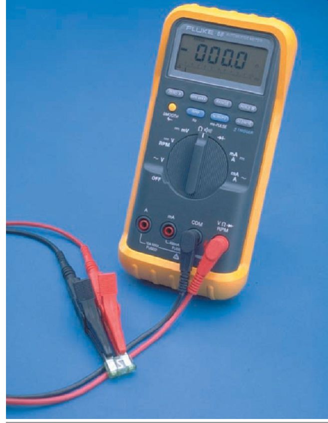
FIG. 15 A digital electrical meter.
Electrical Meters
As you use electrical meters, you'll find that there are three primary types: voltmeter, ammeter, and ohmmeter. A multi-meter is a meter that incorporates the functions of all these three meters. These meters may have either analog- or digital-type displays. Most meters also contain a battery within them. Be sure to turn the meter to the off position when not in use.
Voltmeters
Voltmeters are used to measure the voltage, or potential difference, between two points in a circuit (FIG. 16). A voltmeter can be used to check voltage at any point in a circuit. Remember that voltage is like pressure and exists between two points; it doesn't flow like current. Therefore, a voltmeter isn't connected in series, but must be connected across a circuit, or in parallel (FIG. 17). You can change the meter settings to measure volts in both AC and DC circuits.
Ammeters
Ammeters are used to measure current flow through a circuit. As we know, current is measured in amperes. The scale of an ammeter shows the number of amperes in a particular circuit. Unlike a voltmeter, ammeters are always connected in series in a circuit (FIG. 18). An ammeter must be connected in series because the entire current must flow through both the circuit and the ammeter. As with voltmeters, there are both AC and DC ammeters. Settings can also be changed to measure ampere in AC and DC circuits.
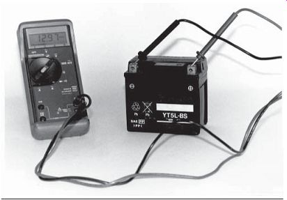
FIG. 16 Voltmeters are used to measure the electric potential difference
between two points.
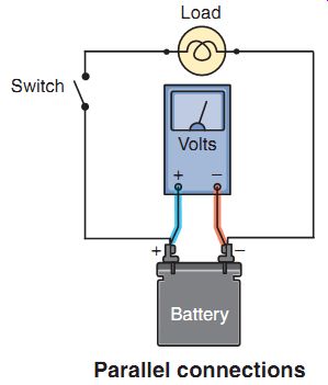
FIG. 17 A voltmeter is connected always in parallel to check the voltage
of the battery.
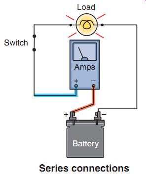
FIG. 18 An ammeter is connected always in series to check the current
draw of the load (i.e., the lightbulb).
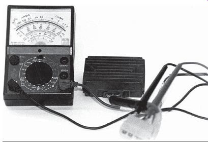
FIG. 19 Ohmmeters are used to measure the resistance of a circuit or
component by applying a known voltage to the circuit and measuring the resulting
current.
Ohmmeters
Ohmmeters are used to measure the resistance of a circuit or component by applying a known voltage to the circuit and measuring the resulting current (FIG. 19). Ohmmeters usually have a built-in power supply, such as a 9-volt battery, which supplies the voltage to test the component. Thus, when connecting an ohmmeter to a circuit, you must be certain the power source is removed from the circuit. It's good practice to disconnect the battery of the power equipment engine when testing using an ohmmeter.
Multi-Meters
A multi-meter is a meter that combines the testing capabilities of a voltmeter, ammeter, and ohmmeter. Multi-meters are the most widely used item among electrical testing equipment in the power equipment engine industry. The multi meter may be referred to as a volt/ohmmeter (VOM), or if it's a digital meter with ampere-testing capabilities, it may be referred to as a digital volt/ohm/amp meter (DVOAM). The DOVAM is also called a digital multi-meter (DMM).
FIG. 20 shows a DMM. A dial on the front of the multi-meter is used to select what you want to measure-voltage, current, or resistance. Many multi-meters will also have range selectors that can be set for the quantity being measured. For example, in our illustration, you can see multiple Direct Current Volt (DCV) ranges: 200 millivolts, 2,000 millivolts, 20 volts, 200 volts, and 1,000 volts. When the selector switch is set to the "20" position, the meter only measures values between 0 and 20 volts, which is the most common range found on power equipment engines.
You'll also note that jacks, which are used to hook up the leads, are used for different testing applications. Having the test leads in the correct jack is crucial in electrical testing.
Multi-Meter Operation
Since multi-meters are the most widely used measurement instruments in the power equipment engine industry, we'll cover their primary functions. But first, let's go through some basic information.

FIG. 20 A multi-meter is a meter that combines the testing capabilities
of a voltmeter, an ammeter, and an ohmmeter and is the most popular electrical
testing tool found in a technician's toolbox.

FIG. 21 Measuring AC voltage from a home electrical outlet.
Measuring AC
The connection of the positive and negative terminals of an AC voltmeter or ammeter doesn't matter because, as you'll recall, AC is constantly reversing itself (FIG. 21). There fore, the positive and negative terminals are constantly alternating from positive to negative and negative to positive.
When measuring AC voltage, certain requirements must be met:
Whenever you're checking for any kind of voltage (AC or DC), the meter must be connected in parallel to the circuit.
We had briefly mentioned earlier that to produce AC voltage, there are three requirements: a magnet, a conductor, and motion. To get an AC voltage reading on a power equipment engine, there must be engine motion, that is, the crankshaft of the power equipment engine you're testing must be turning.
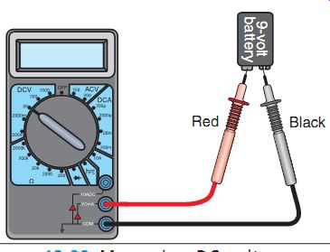
FIG. 22 Measuring DC voltage across a 9-volt battery. Note that the leads
must be connected correctly to yield an accurate reading.
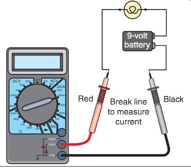
FIG. 23 A multi-meter, when used to measure current, must be connected
in series to the circuit to allow the current to flow through the meter.
Measuring DC
The connection of the positive and negative terminals of a DC voltmeter or ammeter is important.
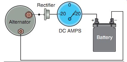
FIG. 24 This ammeter is measuring a rectified current flow into the battery,
at a rate of about 17 amperes.
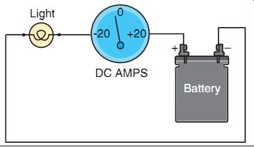
FIG. 25 This ammeter is measuring a current discharge of about 3 amperes
from the battery to the lights.
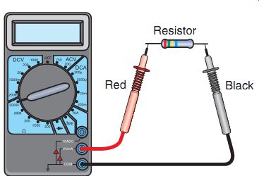
FIG. 26 Resistance is measured with the component disconnected from the
circuit.
When measuring a DC circuit, you must connect the negative terminal of the meter in the circuit toward the negative terminal of the battery (FIG. 22). Likewise, the positive terminal of the meter must be connected in the circuit toward the positive terminal of the battery. If the meter is connected improperly, it will read exactly opposite of the actual measurement! When working on power equipment engines, the only current measurements that you'll take will be for DC. Be sure to hook the meter up in series when checking for DC (FIG. 23). Also be sure to hook the meter leads up correctly. One way to verify that the leads are correctly hooked up is to turn the power on after the meter is connected and look at the reading while the engine isn't running. The meter must read a negative number if the key is on and the engine is off. If the meter is reading a positive number, simply switch the meter leads and check again.
Never electric start a power equipment engine while the ammeter is hooked up in series to the battery. The meter isn't designed to handle the large amount of amperage that the starter motor requires to turn the engine over, and it will almost certainly damage the meter.
A type of ammeter commonly used in connection with power equipment engine electrical troubleshooting is a 20-0-20 DC ammeter.
This meter has a scale with a zero in the center and the number "20" on the far right and far left of the scale. Thus, 20 amperes is the full scale value, or maximum amperage, that can be measured with this instrument. The pointer rests over the zero when no amperes are being measured. When current is being measured, the position of the pointer to the right or left of the zero not only tells you the rate of current flow but also whether current is flowing into or out of the battery. If the needle points to the right side of the scale, it indicates a flow of DC into the battery. In other words, the battery is being charged. If the needle points to the left side of the scale, it indicates that current is flowing from the battery. In other words, the battery is being discharged. Let's look at a couple of examples.
On a power equipment engine, AC power flow is converted to DC and is delivered to the battery where it's then stored (FIG. 24). Before it reaches the battery, it flows through a component called a rectifier, which changes the AC to DC. Therefore, to check the current, you would connect a DC ammeter between the rectifier and the battery. In this example, our ammeter is reading a current of about 17 amperes.
This tells us that the battery is being charged.
If an ammeter were connected between the light and the battery on our implement with the key on and engine off, the ammeter would read a current of negative amperage (FIG. 25). In this scenario, the battery is being discharged.
Measuring Resistance
As we discussed earlier, whenever you're using an ohmmeter, it's important to first disconnect the component being tested from the rest of the electrical system (FIG. 26). In other words, isolate and de-energize the component. If you don't isolate the component from the rest of the electrical system, you risk damaging the meter.
You may also receive a false resistance reading, as there may be other resistances in the circuit that you're about to test.
Precautions when Using a Multi-Meter
You can destroy a multi-meter if you use it improperly. Here are some basic steps you should know about how to operate a multi meter:
1. Determine what you want to measure (volt age, current, or resistance).
2. Set the meter up to the proper unit of measurement (volts, amperes, or ohms).
3. Connect the test leads to the meter.
4. Select the quantity you want to measure by turning the dial.
5. Holding the two test leads, touch the probes with two points in a circuit.
6. Read the resulting information on the meter's display.
Note that this is a basic description of the operation of a multi-meter. The actual operation may be somewhat different than described here; so be sure to read the instruction manual provided with the meter.
As a general note, when you're using meters, you need to ensure that they're connected properly to the circuit being tested. An improper connection can result in an incorrect measurement and, in some cases, damage the meter. When using an analog meter, it's also important that you learn to read the scales on each meter scale properly.
Voltage Drop
As previously discussed, voltage is the electrical force or push of electricity. Voltage drop is the consumption of the available voltage from the battery as it crosses some form of resistance, such as a lightbulb or a switch. A voltage drop measurement allows you to identify if all of the available voltage is being used up by the component it's intended to power.
When electrical current reaches a load, such as a lightbulb, current is forced through the filament of the bulb. Each connection in a circuit offer's a very slight resistance to electron flow.
Normal voltage drop for a connection in a circuit is 0.1 (one-tenth) volt or less.
Generally speaking, in the power equipment engine industry, voltage drop should not exceed the limits set (for the following components):
Wires or electrical cables: 0.2 VDC
Switches: 0.3 VDC
Electrical connections: 0.1 VDC
Electrical grounds: 0.1 VDC
As you would recall, current remains the same throughout any circuit; what is lost or used up is the voltage. Therefore, if you measure 12 volts before the load and 0 volts after the load, all is working well. However, if the full 12 volts isn't powering the load, there is unwanted resistance somewhere in the circuit. Now, it must be determined if the unwanted resistance is before or after the load. You can quickly isolate the area of the unwanted resistance by dividing the circuit in two: positive and negative.
The purpose of any circuit is to allow an electrical load to operate as designed. No matter what the load is--a lightbulb, a clock, a starter motor, or an electronic control module--it must have power to it and it must have a ground to make the circuit complete.
The voltage supplied is consumed by the load as it operates. This provides a clue that makes troubleshooting electrical problems much simpler. We know that voltage is going into the load and being consumed within the load. Therefore, in a basic circuit, we should have full source voltage from the battery to the load, and since the load consumes the voltage as it operates, we should have 0 volts coming out of the load.
So remember: you should expect about 12 volts (depending on the total source voltage on hand) on the positive side, and 0 volts on the negative side of the load (FIG. 27).
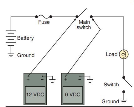
FIG. 27 Testing the positive side of an electrical component in a circuit
should show the source voltage, whereas testing on the negative side of the
circuit should read zero or near zero volts. This is known as voltage drop.
MAGNETISM
Magnetism, like electricity, is a force we can't see. However, like electricity, we can observe its effects. The subject of magnetism isn't completely understood, and most of it's well beyond the scope of this guide; however, it's important for you to understand some basics about magnets so that you can understand better how alternators and generators produce electricity in a power equipment engine.
Many years ago, scientists discovered that fragments of iron ore attracted each other.
Researchers also found that when a magnetized iron bar was suspended in the air, one end would always point north. This was called the north "pole" of the magnet. The opposite end of the bar came to be known as the south "pole" of the magnet.
It was also found that when a piece of non magnetized metal, such as steel, was rubbed over a magnetized metal, the magnetic properties of the metal were transferred to the steel.
The area affected by a magnet is called the field of force or magnetic field (FIG. 28a). Note that the "lines" of force, or flux lines, as they're sometimes called, are for illustrative purposes only-we can't actually see the lines. Well, actually, we can see the lines if we do a small experiment using a magnet, a sheet of paper, and iron filings. If we place a sheet of paper over a magnet and then sprinkle iron filings over the paper, we'll see the iron filings aligning them selves along the magnetic lines of force created.
This is one way we can "see" magnetic lines of force. As with electricity, one important property of magnets you should know is that opposites attract. When opposite poles of a magnet or magnets are placed near each other, they'll attract each other (FIG. 28b). Conversely, when two like poles are placed together, they'll repel each other (FIG. 28c). This is because the lines of force are going in opposite directions. Another property of magnets is that when a nonmagnetic substance (such as a piece of wood) is placed in a magnetic field, the lines of force aren't deflected. Magnetic forces pass through nonmagnetic materials!
Types of Magnets
There are three types of magnets. Let's briefly describe them now:
Magnetite . A natural magnet, it occurs in rock form. It's a weak magnet and isn't used in power equipment engine components.
Permanent magnet . A man-made material, a permanent magnet is very strong and long lasting. Permanent magnets are found commonly in different parts of power equipment engines.
Electromagnet . An electromagnet, which is also man made, is another magnet that may be found in power equipment engines. An electro magnet consists of a coil wound around a soft iron or steel core. The core becomes strongly magnetized when current flows through it and becomes almost completely demagnetized when the current flow is interrupted; hence the term electromagnet, as it combines electric current with magnetic properties.
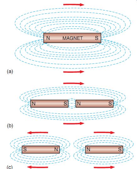
FIG. 28 (a) The area affected by a magnet is called the field of force
or magnetic field. (b) When opposite poles of a magnet or magnets are placed
near each other, they attract each other. (c) When two like poles are placed
together, they repel each other.
Magnetic Forces
Magnetic force is the amount of force exerted between two opposite magnetic poles, which produces magnetism. There are different ways to control and create magnetic forces of desired strength.
Let's look at the most common types of magnetic forces used in a power equipment engine.
Electromagnetism
The concept of electromagnetism is important to the operation of electrical systems used in power equipment engines. Electromagnetism is the magnetic effect produced when an electric current flows through a conductor (wire).
When the current flows through the wire, the wire becomes surrounded by a magnetic field (FIG. 29). The magnetic field is strongest in the space immediately surrounding the conductor.
Magnetic Coils
Electromagnetism has many interesting and highly useful applications. If an insulated piece of conductor wire is looped around an iron bar to form a coil, the resulting device is called a magnetic coil (FIG. 30). When current flows through a magnetic coil, each separate loop of wire develops its own small magnetic field. The small magnetic fields around each separate loop of wire then combine to form a larger and stronger magnetic field around the entire coil. The coil develops a north pole and a south pole. The magnetic field at the center of a magnetic coil is stronger than the fields above or below the coil.
Magnetic Induction
When a conductor (wire) is moved through a magnetic field so that it moves across the lines of force, an electromotive force (EMF), or potential voltage, is induced in the wire.
If the wire is part of a complete electrical circuit, a current will flow through the wire. This important fact is the working basis for the various kinds of AC-producing generators used in power equipment engines. This kind of generator may also be called an alternator. We'll explain electricity-generating systems in greater detail in Section 14, but it's important for you to understand that they all function on the basis of the same principle.
That principle is that when an electrical conductor is passed through a magnetic field (or a magnetic field is moved past an electrical conductor), an electric current, or voltage, is induced in the conductor wire. This effect is called the generator action of magnetic induction. Note that current won't flow through the wire until the wire is connected in a complete circuit.
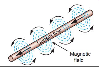
FIG. 29 When current flows through wire, a magnetic field is produced.
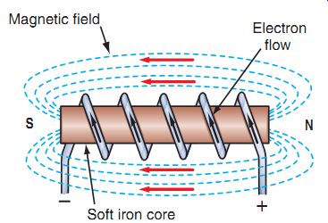
FIG. 30 A magnetic field can become highly concentrated when an iron
core is installed in a coil of wire.
Mutual Induction
The final electromagnetic property we'll look at is called mutual induction. If two conductors are placed close together and current is applied to one of the conductors, a voltage will be induced in the other conductor. This occurs because when two conductors are physically close to each other, the energy in the live conductor will stimulate the other conductor to become energized too. This effect is called mutual induction, and it can be used to operate ignition coils. Note that if the conductors are moved apart from each other, the effect of mutual induction isn't as great. If the conductors are moved sufficiently far apart, the energy of the live conductor won't be strong enough to influence the other conductor, and the mutual induction effect will cease.
In Section 15, we'll see how the principle of mutual induction is used to help operate a power equipment engine's ignition system.
AC Generator Operation
The generator action of magnetic induction is fundamental to operating a charging system in an engine. We'll discuss this property using FIG. 31, which shows a very basic AC charging system. A permanent magnet is suspended within a soft iron frame, which completes the circuit for the permanent magnet's lines of force. The soft iron core becomes a temporary magnet, concentrating lines of magnetic force around the coil of wire in the magnetic field to produce an electric current. The coil, known as a stator in a charging system, is made up of many loops of conductor wire. As the magnet rotates, the magnetic polarity of the soft iron frame is reversed. With each 180° of rotation, the magnetic lines of force around the soft iron frame collapse and then reestablish themselves in the opposite direction. Each time the lines of force collapse and rebuild, the coil of wire within the magnetic field cuts them and an electric cur rent is produced.
The voltage and current produced by the simple generator shown would be quite low. But if we wound many loops of wire into a coil and rotated the coil in the magnetic field, a much larger voltage and current would be produced.
This is the arrangement in a real AC generator.
The amount of voltage and current produced by a generator is based on:
- The number of turns in the coil and the diameter of the wire
- The strength of the magnetic field
- The speed at which the wire coil passes by the magnets
All power equipment engines that use a battery use the AC generator action of magnetic induction, which is changed to DC to charge the battery through rectification. In such implements, generators charge the batteries, and the energy from the batteries is then used to power the various electrical systems. It should be noted that AC generators are sometimes called alternators, depending on the manufacturer.
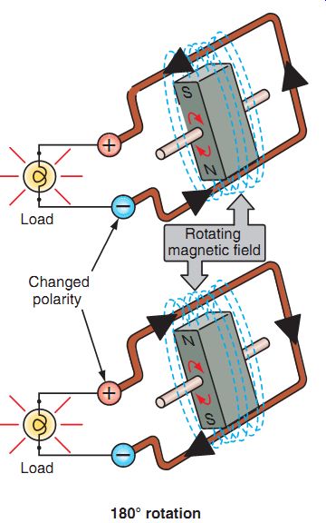
FIG. 31 In this AC generator, as the magnet rotates, the induced current
reverses.
Solenoids
Some electromagnets have special movable cores. This type of electromagnet is called a sole noid or relay. Inside the solenoid coil, there is a movable piece of metal called a plunger. When a solenoid coil is energized by a flow of current, the resulting magnetic field moves the plunger in the coil. When the flow of current stops, a spring forces the plunger back into its original position.
Solenoids are used in electric starter systems as well as in some safety devices in power equipment engines. Solenoids are designed in one of two designs:
A normally open solenoid is a solenoid that doesn't allow current flow unless the solenoid is activated. This type of solenoid is found in electric starting systems and allows a high current flow after a very small current flow activates the solenoid.
A normally closed solenoid is a solenoid that allows current to flow unless the solenoid is activated. This type of solenoid is found in safety devices, such as lockout safety devices, and creates an open circuit after a very small current flow activates the solenoid.
Electromagnetism in Motors
You've just learned that when a conductor moves through a magnetic field, a voltage is produced in the conductor. Now, suppose that a current-carrying conductor is placed in a magnetic field. What happens? Well, the interaction between the magnetic field and the moving electrons in the conductor causes a physical force that's applied to the conductor. If the conductor is free to move, this physical force will cause the conductor to move for as long as the conductor current and the magnetic field are maintained.
This property is called the motor action of electromagnetic induction.
The motor action of electromagnetic induction is shown in FIG. 32. In this figure, a conductor (wire) is connected to a battery to form a complete circuit. Current is already flowing in the conductor when it's placed in a magnetic field between two magnets. The reaction between the magnetic field and the moving electrons in the conductor causes the conductor to rotate, as shown by the arrow in the figure.
The motor action of electromagnetic induction is the basic property that's used to operate electric starter motors.
FIG. 33 shows the basic parts of an electric starter motor. The armature in a starter motor is a rotating component that's mounted on a shaft and positioned between the motor's field magnets. Loops of conductor wire, called armature windings, are connected to the armature's commutator. Note that for simplicity, only one winding is shown in the figure. Brushes are electrical contacts that slide over the surface of the commutator when the armature rotates. The brushes are connected to a battery. Electrical wires, called field windings, are wound around the field magnets. When current flows into these wires, the field magnets become electromagnets and produce a powerful magnetic field inside the motor. When current is applied to the brushes, the current moves through the brushes and into the commutator and armature windings. The current flowing through the armature windings produces magnetic fields around the windings.
The interaction of all these powerful magnetic forces causes the armature to spin.
FIG. 32 When the field windings are energized, the field magnets produce a magnetic field in the motor. When current flows through the armature windings, magnetic fields are produced around the windings. The interaction of these fields causes the armature to rotate.
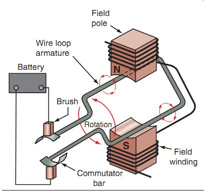
FIG. 33 The basic parts of an electric starter motor.
Many power equipment engines use electric starter motors. The output shaft of the electric motor in such a system is generally connected to gears that engage the crankshaft of the power equipment engine. The spinning motion of the electric motor's armature is transferred through these gears to the crankshaft. Some people may use the word motor when talking about either the electric starter motor or the power equipment engine. Don't confuse the starter motor with an engine!
ELECTRONIC DEVICES
Now you should have a basic understanding of the principles of electricity and magnetism. Now let's take a brief look at some electronic devices.
We'll start by reviewing a few terms. You'll remember that a conductor, such as a copper wire, is a material that allows electrical current to flow through it easily. An insulator, such as plastic or nylon, is a material that resists the flow of electricity through it. There are other materials called semiconductors, which as the name implies, allow some flow of electricity through them.
A semiconductor is a substance whose electrical conductivity is between that of a conductor and an insulator. A semiconductor's electrical conductivity also increases as its temperature increases. Silicon, germanium, and selenium are common semiconductor materials that are used to make electronic components.
Semiconductor devices are manufactured in laboratories under very special conditions.
Semiconductor materials are specially processed and combined to form electronic devices such as diodes and transistors, which are capable of controlling the flow of electrons in a way normal conductors can't. So, as a result of these special manufacturing processes, the conducting and insulating properties of semiconductor materials can be used to perform useful work in a circuit.
Electronic Components
Electronic devices contain components that are used to control the flow of electrons in a circuit. Many electronic components are used in circuits in power equipment engine electrical systems, but we'll look just at the most common ones. These devices are the diode, the zener diode, the transistor, and the silicon-controlled rectifier (SCR).
Diodes
A diode is a simple electronic device that has two terminals and acts like a one-way valve.
The two terminals are called the anode and the cathode. The anode is the positive (+) terminal, whereas the cathode is the negative (-) terminal.
When a positive voltage is applied to the anode of a diode, electric current moves through the diode and exits at the cathode. In this situation, the diode acts like a conductor. When a positive voltage is applied to the cathode of a diode, the diode resists the flow. Current won't flow through the diode. In this situation, the diode acts like an insulator. Diodes allow cur rent to flow through them in one direction only.
The electrical symbol for a diode (FIG. 34) illustrates this principle.

FIG. 34 The electrical symbol for a diode.
A diode will allow electrical flow in only one direction.
Zener Diodes
Like a regular diode, a zener diode allows current to flow in one direction. However, the zener diode allows current to flow in the opposite direction also if the voltage exceeds a pre determined value (FIG. 35). Thus, at a predetermined voltage, called the reverse or breakdown voltage, the zener diode becomes conductive in the opposite direction also. This characteristic makes the zener diode useful for voltage regulation in power equipment engine charging systems.
Silicon-Controlled Rectifiers (Thyristors)
An SCR is another type of semiconductor component. SCRs are used as switching devices in electronic circuits. An SCR, often called a thyristor, has three terminals: the anode, the cathode, and the gate. Except for the gate, the construction of an SCR is similar to that of a diode (FIG. 36).
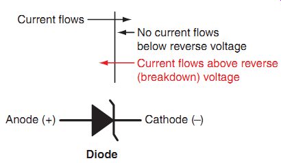
FIG. 35 A zener diode allows current to flow in the reverse direction
only when a predetermined voltage is sent in the opposite direction.
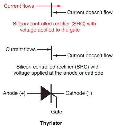
FIG. 36 An SCR, or thyristor, is a diode with a gate that allows current
to flow only when a predetermined voltage is applied to the gate.
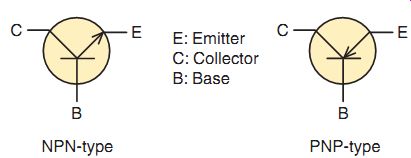
FIG. 37 The electrical symbols of the PNP and NPN transistor types.
Unlike a diode, an SCR will block current in both directions. If you apply a voltage across an SCR, current won't flow. If a small amount of voltage is applied to the gate of an SCR, how ever, current will flow through the SCR in the forward direction. Current will continue to flow until the voltage is removed from the gate. Thus, an SCR can be switched on and off by applying a voltage to the gate. In Section 15, we'll look at how these electronic components function in electronic ignition system and charging system circuits.
Transistors
A transistor is another type of semiconductor device that's widely used in power equipment engine electrical systems. Transistors are used to control the flow of current in a circuit and function like relays. They switch a current on and off when they receive a small current. The key difference between a relay and a transistor is that a transistor has no moving parts.
A transistor has three wire terminals: the base, the collector, and the emitter. There are two types of transistors: PNP and NPN (FIG. 37).
With PNP-type transistors, when positive voltage is applied to the emitter and the base is at a lower voltage level, a small current flows from the emitter to the base, during which time, a large current flows from the emitter to the collector (FIG. 38).
With NPN-type transistors, no current flows when a positive voltage is applied to the collector and a negative voltage to the emitter. When a small current flows from the base to the emitter, a large current flows from the collector to the emitter.
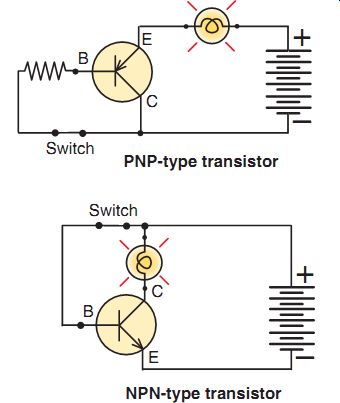
FIG. 38 The circuitry of the PNP and NPN transistors and their power
flow.
ELECTRICAL SCHEMATICS AND SYMBOLS
Before you can begin working on a power equipment engine electrical system, you must know how to read electrical schematics (also known as wiring diagrams). A schematic is like a road map but instead of connecting cities and towns through the numerous roads and highways, it connects the wires in the electrical system to the various components that require electricity to function properly. Schematics use symbols to describe the various components in the system. FIG. 39 shows some of the most common types of electrical symbols used on power equipment engine wiring diagrams.
All manufacturers use schematics to assist you with tracing a wire to a component. In general, manufacturers use certain colors to help you to know right away whether the wire you're looking at leads to the component you're trying to test or trace. However, such color coding is not standardized. For instance, some manufacturers use the colors green for ground and black for switched-on power, whereas some other manufacturers may use these colors for an entirely different electrical action. It's because of this possibility that you must rely on the manufacturer's service manual to ensure that you're on the right path. Although some manufacturers illustrate their schematics in full color, most use simple black-and-white diagrams in their service manuals (FIG. 40).
To assist a technician with diagnosis of an electrical complaint, most manufacturers create a more precise schematic of the various subsystems within the electrical system of the power equipment engine. These are known as block diagrams. With a block diagram, you can separate the desired subsystem, such as the ignition system (FIG. 41) or the charging system (FIG. 42) from the rest of the implement.
This helps the technician focus on the system in question.
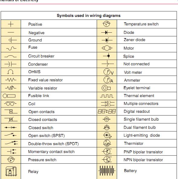
FIG. 39 Some of the most common electrical symbols found on a power equipment
engine schematic or wiring diagram.
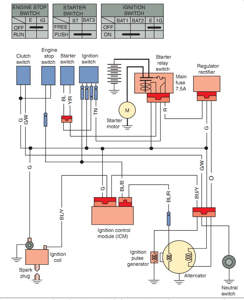
FIG. 40 A complete schematic.
FIG. 41 A typical block diagram of an ignition system. Block diagrams
separate the system you're looking at from the rest of the electrical system.
This aids in diagnosing problems within the system in question.
FIG. 42 A typical block diagram of a charging system.
ELECTRICITY TERMS
The following terms are found often in material related to electrical repairs. Your job as a technician will be much easier if you know and understand these terms. For ease of reference, they're listed in alphabetical order. Many of these terms have been discussed in this section, but those not discussed are important terms to understand just as well.
AC Abbreviation for "alternating current"; is one form of electric current that reverses direction and polarity while flowing through a circuit, e.g., a 110-volt AC in household electrical systems reverses direction and polarity 60 times per second (60 Hz) Alternator An AC generator that uses magnetic induction to produce electricity; a revolving magnet and stationary stator windings are used, and the current produced is AC Amperes Commonly called amps; electrical unit of current flow through a circuit (similar to gallons per minute of water through a hose) Amp hour Discharge rate o
Armature A group of rotating conductors that pass through a magnetic field; the cur rent produced, after the conductors are passed through a commutator device, is usually DC; armatures are also used in electric motors
Battery A chemical device used to store electrical power; within the battery, a chemical reaction takes place that produces a volt age potential between the positive and negative terminals Bench test Isolated component inspection
Capacitor Also called condenser; a component which, in a discharged state, has a deficiency of electrons and will absorb a small cur rent and hold it until it's discharged again
Circuit Composed of three components/ requirements: a power supply, load, and completed path
Circuit breaker Heat-activated switch that interrupts current when overloaded; a circuit breaker can be reset and replaces the function of a fuse
Coil A conductor looped into a coil-type configuration which will produce a magnetic field when current is passed through it
Conductor A wire or material (such as a frame) that will allow current to flow through it with very little resistance
Continuity A continuous path in a circuit for current to flow
Current The flow of electrons in a circuit
DC Abbreviation for "direct current"; one form of electric current in which current flows only in one direction-from positive to negative, per the conventional theory
Dielectric A nonconductor of electricity; dielectric materials don't allow electricity to flow through them. See also insulator Diode A semiconductor often used in a rectifier in power equipment engines; a diode has the characteristic of allowing current to pass through in only one direction, and it's thus used to change AC to DC Dynamic Spinning or rotating in motion; refers to making a test when the component is in use
Electricity The flow of electrons through a conductor Electron The revolving part or moving portion of an atom; electrons moving from atom to atom constitutes electrical current Electrolyte The sulfuric acid and distilled water solution that batteries are filled with at setup Electromagnet A coil of wire that is wound around a soft iron core; acts as a magnet when current is passed through it Electromotive force Abbreviated as "EMF"; the pressure of electrons in a circuit (also known as voltage); created by difference in potential between positive and negative terminals of power supply; also called pushing force of electricity Electrolysis The movement of electrons through an electrolyte solution; a battery charges and discharges through electrolysis; electroplating (chroming) is an example where electrolysis is used to move and deposit metals from one electrode to another; in cooling systems, contaminated coolant (tap water) becomes an electrolyte, allowing electrolysis and the deposition of metal oxide scale on cooling system components Free electron An electron in an atom's outer orbit, which is held only loosely within the atom; free electrons can move between atoms
Field coil An electromagnet; the flux lines may be used for generating electricity, for electric motor operation, or for operating a solenoid/ relay
Fuse A short metal strip that's protected by a glass or plastic case that's designed to melt when current in the circuit exceeds the rated value
Flux lines All the magnetic lines of force from a magnet
Ground A common conductor used to complete electrical circuits (negative side); the ground portion of power equipment engine electrical systems is often the frame
Ignition The spark produced by the high-tension coil by which the spark plug ignites the air-fuel mixture
Insulator A material that does not conduct electricity, thereby preventing the passage of electricity; all electrical wires are protected by a plastic or special rubber insulation
Lines of force Refer to a magnetic field whose lines run from its north pole to its south pole.
See also Flux lines Load Anything that uses electrical power, such as a lightbulb, coil, or spark plug Magnetism The characteristic of some (ferrous) metals to align their molecules in a particular direction; the alignment of the object's molecules will cause the object to act as a magnet; every magnet has both a north pole and a south pole; like polarities repel, opposites attract; around every magnet, there's a magnetic field, which contains lines of force Magnetic induction Introduction of electricity in a circuit when a conductor is moved through a magnetic field; occurs when the flux lines of the magnetic field cut through the conductor No-load test A dynamic test with the component insulated or disconnected from its main system NPN A transistor in which the emitter and collector layers are N-type and the base layer is P-type (negative, positive, negative) Permeability Ability of material to "absorb" magnetic flux; can be temporary or permanent.
See Reluctance Pole The north "pole" or south "pole" of a magnet; also refers to the lugs (iron cores) of a stator around which the AC generator's wires are wound Polarity In magnets, polarity is north and south; in electricity, polarity is positive and negative PNP Transistor in which the emitter and collector layers are P-type and the base layer is N-type (positive, negative, positive) Rectifier Changes AC to DC; usually a group of four or six diodes comprises a bridge rectifier. See Diode Regulator Used to limit the output of a generator or alternator
Resistance The opposition offered to the flow of current in a circuit
Rotor The revolving magnets or electromagnets that form the magnetic field in an alternator or ignition signal generator Reluctance Resistance to magnetism. See also Permeability Reluctor Magnetic field interrupter used as a signal generator in ignition systems Silicon A material used in the construction of semiconductors; because of its characteristics, the material allows current flow only under certain predetermined conditions Sine wave A graphic depiction of the form of AC usually taken from an oscilloscope SCR An abbreviation for silicon-controlled rectifier, which is an electronically controlled switch. See Thyristor Selenium Similar to silicon materials in characteristics; it's used as a rectifier on older models Solder Tin-lead alloy with rosin core used to form lower-resistance connections of electrical components or wires Static Stationary; usually a test made of a stationary component rather than a bench test Stator A stationary conductor (usually several coils of wire); when magnetic flux cuts the stator windings, a voltage potential is induced in the windings Switch A device that opens or closes an electrical circuit Schematic A wiring diagram showing in detail the electrical components and circuitry Thermo-switch A bimetallic switch that, when heated, opens or closes a circuit
Thyristor An electronically controlled switch that opens when signaled at the gate and closes after current flow falls Unloaded See No-Load Test Valence electrons The electrons contained in the outermost electron shell of an atom; also known as free electrons Voltage See Electromotive Force Watt The unit of electric power; W = E × I (wattage = voltage × current) Wire gauge Wire diameter; usually specified by an AWG (American Wire Gauge) number; the smaller the number, the larger the wire diameter Wiring diagram Similar to a schematic, but less in detail; a wiring diagram usually shows components in block form rather than illustrating their internal circuitry Zener diode Similar to a standard diode, but allows current flow in the reverse direction when the breakdown voltage is reached
Summary
Electrical devices and circuits can be dangerous. Safe practices are necessary to prevent shock, fires, explosions, mechanical damage, and injuries resulting from the careless or improper use of tools.
There are two theories of electricity: the conventional theory of electricity and the electron theory of electricity.
There are three types of electrical circuits: series circuit, parallel circuit, and series/parallel circuit.
Voltage, resistance, and current are common terms used with electricity.
The amount of current flowing through a completed circuit is directly proportional to the voltage applied to the conductor, provided resistance is maintained constant.
This relation between resistance, current, and voltage is known as Ohm's law.
The multi-meter is the most widely used electrical testing tool in the power equipment engine industry and integrates three measuring devices into one handy-to-use tool: the voltmeter, the ammeter, and the ohmmeter.
Before you can begin working on a power equipment engine electrical system, you must know how to read electrical schematics (also known as wiring diagrams).
QUIZ
1. A circuit that has more than one path to the power source is a
a. series circuit.
b. open circuit.
c. parallel circuit.
d. short circuit.
2. When a conductor is moved through a magnetic field, a voltage is induced in the conductor. However, current won't flow through the conductor unless it's
a. formed into a coil.
b. connected in a complete circuit.
c. moved very quickly through the magnetic field.
d. made of copper.
3. What is the voltage of a circuit having a current flow of 3 amperes and a resistance of 4 ohms?
a. 0.12 V
b. 12 V
c. 7 V
d. 36 V
4. A circuit that has an incomplete path for current to flow is called
a. a grounded circuit.
b. an open circuit.
c. a short circuit.
d. a closed circuit.
5. EMF is measured in
a. watts.
b. ohms.
c. amperes.
d. volts.
6. An ohmmeter is always connected to an electrical circuit
a. in series.
b. to measure voltage.
c. after the component being tested has been isolated from the rest of the electrical system.
d. after the power has been turned on.
7. The terminals of a diode are the
a. gate, anode, and cathode.
b. primary and secondary.
c. emitter, collector, and base.
d. anode and cathode.
8. What would be the resistance of a 12-volt lightbulb with 5 amperes flowing through it?
a. 2.4 ohms
b. 2.4 volts
c. 0.416 ohms
d. 0.417 volts
9. An ammeter is always connected to an electrical circuit ...
a. after it has been isolated from the rest of the electrical system.
b. in parallel.
c. in series.
d. after the power has been turned on.
10. The conventional current flow theory can best be described as
a. electron flow from the negative terminal to the positive terminal.
b. electron flow from the cathode terminal to the anode terminal.
c. electron flow from AC to DC and then back to AC.
d. electron flow from the positive terminal to the negative terminal.
11. Electrical current flow is measured in
a. ohms
b. amperes
c. watts
d. volts
12. The abbreviation "AC" stands for .
13. The abbreviation "DC" stands for .
14. With a , you can separate the desired subsystem, such as the ignition system, from the rest of the schematic.
15. Which theory of electricity is used in explanation of electrical circuits in the power equipment engine industry?
a. Electron
b. Electro-conventional
c. Conventional
d. Nonconventional