AMAZON multi-meters discounts AMAZON oscilloscope discounts
Goals:
- Explain why power equipment engines have charging systems
- Describe the theory behind a basic charging system
- Visually identify from a schematic the different types of charging systems found in power equipment engines
- Describe how alternators generate AC power
- Describe how a charging system converts AC to DC
- Read block diagrams for various DC electrical system circuits
INTRODUCTION
This section is the second of three sections devoted to electrical systems in power equipment engine. In Section 13, you learned about the basics of electricity, where electricity comes from, and how to measure it. In this section, you'll learn how to apply this electrical theory to understand power equipment engine charging and other related electrical systems. We'll begin by describing the basics of a charging system. Next, we'll take a closer look at each of the components in the charging system and how they operate. After we've discussed each of the components, we'll review the overall operation of the charging system, and explain how to maintain and troubleshoot components. We'll then take a look at some of the other electrical circuits found in power equipment engines.
A charging system is necessary in any power equipment engine that uses a battery to assist with powering electrical components. As in Section 13, we'll start with the basics. To understand how a charging system works, you must first understand what a charging system does. Then, you need to know the components that make up the charging system and how they work. You'll find that many of the figures in this section are line drawings of the components discussed. This is to allow you to understand better how these components are illustrated in the manufacturer's service manual. You'll also be shown actual images of the components on a power equipment engine.
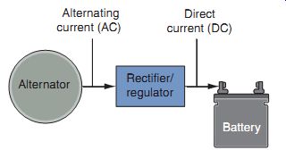
FIG. 1 A block diagram of a simple charging system. All charging systems
have the same basic components.
CHARGING SYSTEMS
The purpose of a charging system is to replenish the voltage in a battery as it's used when the power equipment engine is operating. An alternator generates the electrical power source in the charging system. The alternator provides an alternating current (AC) output, but, as we know, a battery stores direct current (DC).
In order to convert the AC output of the alternator to DC, which is what is needed by the battery, a rectifier is used. The rectifier converts the AC (which, you'll remember, alternately flows in one direction, and then in the other direction) into DC (which flows in only one direction). This process is known as rectification. The voltage from the charging system to the battery is maintained within a predetermined range by a voltage regulator. By controlling the output of the charging system, the voltage regulator prevents undercharging or overcharging the battery.
From the smallest single cylinder engine to large multi-cylinder power equipment engines, all charging systems have the same common basic components (FIG. 1). Although these components may have different designs and sizes in various power equipment engines, they all perform the same functions.
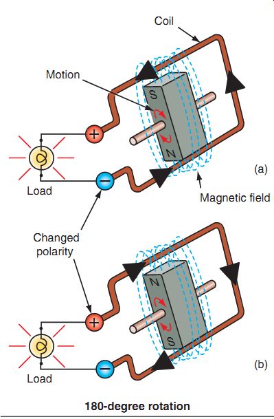
FIG. 2 The three key requirements needed to produce AC voltage are a
magnetic field, a conductor (coils of wire), and motion. (a) Current flow in
one direction; (b) Current flow reverses direction. This creates alternating
current (AC).
The Alternator
Depending on the manufacturer, there are many terms used for an alternator, some of which are generator, dynamo, and magneto. For the purpose of this section, we'll simply refer to it as alternator as it's used to create AC. The alternator is driven by the rotation of the engine's crankshaft and may be directly connected to the crankshaft or it may be driven by a gear and placed elsewhere on the power equipment engine, depending on the size of the machine it's connected to. An alternator produces electrical output only when the crankshaft is rotating. Remember from Section 13 that there are three key requirements needed to produce AC voltage: a magnetic field, a conductor (coils of wire), and motion (FIG. 2). The output from the alternator varies with the speed of the engine. The faster the engine's crankshaft turns, the stronger the AC voltage that is produced.
An alternator has two main components: the rotor and the stator. The rotor has a series of magnets and rotates either inside or outside the stationary windings of the stator. The stator consists of sets of coils, which are used to pro duce power for the power equipment engine's electrical circuits and to charge the battery.
From the viewpoint of design and construction, alternators used in the power equipment engine industry can be divided into two general types: permanent-magnet alternators and excited-field electromagnet alternators.
Permanent-Magnet Alternators
The permanent-magnet alternator (FIG. 3) is the most commonly used type of AC generating system found in power equipment engines.
You'll find this type of alternator as an integrated component under the flywheel cover, with the flywheel mounted directly on the crankshaft (FIG. 4). Permanent magnets are incorporated into the flywheel on the rotor (FIG. 5). With this design, the flywheel is fitted onto the crankshaft and is held in place by a woodruff key (FIG. 6) and a mounting bolt. In most cases in power equipment engines, the stator will be located on the crankcase (FIG. 7).
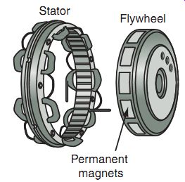
FIG. 3 Permanent-magnet systems are the most popular types of charging
systems found in power equipment engines.
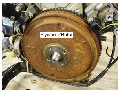
FIG. 4 Permanent-magnet charging systems are generally located on the
crankshaft of the engine under an engine cover.
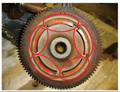
FIG. 5 Permanent magnets are attached to the rotor.
Woodruff key
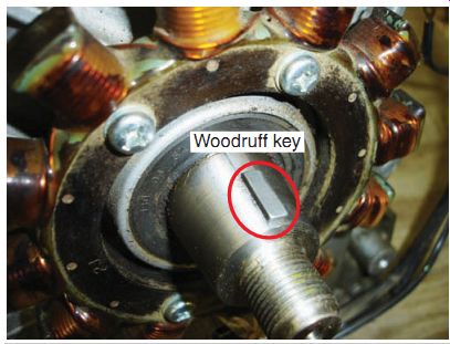
FIG. 6 Alternator rotors are held in place generally by a woodruff key.
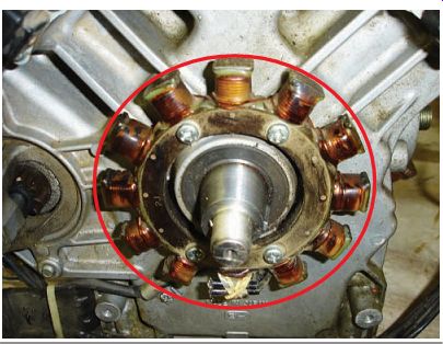
FIG. 7 The stator is mounted onto the crankcase in most power equipment
engines.
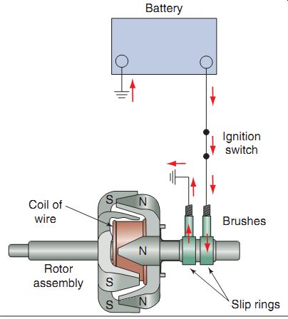
FIG. 8 A diagram of a simple brush-type excited-field alternator.
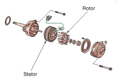
FIG. 9 A brushless-type excited-field alternator.
Excited-Field Electromagnet Alternators
Excited-field electromagnet alternators don't use a permanent magnet. Instead, they have a field coil, which, energized with DC, becomes a powerful magnet. Power is generated as the rotor spins past the stator. Excited-field electromagnets are located in different areas of the engine besides the crankshaft to help cool them, as in the case of the permanent-magnet alternator. When not connected to the crankshaft directly, the rotor's speed can be multiplied by gears or chains. This is done to increase the rotor's speed of rotation if it's deemed necessary by the manufacturer.
The excited-field alternator is potentially the most powerful AC generator available because of the strong magnetic fields that it can create.
In most cases, the excited-field alternator will be found in larger, multi-cylinder engines and is fully self-contained, just as an alternator in an automobile. There are two types of excited field electromagnet alternators, brush-type and brushless-type, which we'll discuss now.
Brush-Type Excited Field
The brush-type excited-field coil has the field coil placed within the rotor (FIG. 8). Current flows through carbon brushes to the field-coil slip rings. When the carbon brushes are energized, current is induced in the rotor electromagnetically, and the rotor becomes a strong magnet. The rotation of the magnetized core acts on the stator coils to produce AC.
Brushless-Type Excited Field
The brushless type excited-field coil (FIG. 9) has the rotor placed around the inner field coil, thereby eliminating the need for maintenance, which is required with the excited-field coil. When the field coil is energized, the magnetic field magnetizes the rotor core. The rotation of the magnetized core acts on the stator coils placed on the out side of the rotor to produce AC.
The Rectifier and the Voltage Regulator
A rectifier is required to convert the AC from the alternator into DC that is used by the battery. The rectifier uses a diode or a group of diodes to convert the AC into DC. It does this by preventing the negative half of the AC from progressing, thereby allowing only current in the positive half to flow. Voltage regulators are used to allow current to flow into the battery to charge it when needed and also to stop cur rent flow to the battery to prevent it from being overcharged. Virtually all voltage regulators use thyristors (SCRs) and zener diodes, which pro vide a current-limiting function to control battery charging.
Although they're two separate components, voltage regulators and rectifiers are generally integrated as a single unit to reduce the cost of production (FIG. 10).
FIG. 11 shows a simplified schematic of a charging system. Note the dashed lines surrounding the regulator/rectifier. Inside the lines you can see diodes and SCRs. Diodes make up the rectifier, whereas SCRs are used for the regulator. To ease your understanding of these critical components of a power equipment engine charging system, we'll discuss the rectifier and regulator separately even though, in practice, they're generally combined as one unit.
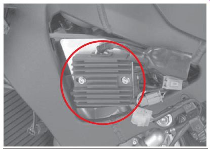
FIG. 10 A voltage regulator/rectifier. The cooling fins help remove the
heat produced from the regulator when it sends excess current back to ground.
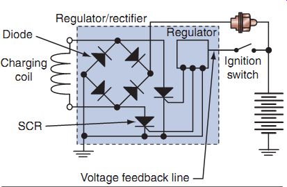
FIG. 11 Although two separate components, the regulator and the rectifier
are generally assembled as one unit, as shown by the dashed lines in this illustration.
Rectifiers
The purpose of a rectifier is to change the AC that's produced by the alternator into DC to charge the battery. A rectifier may consist of one to six diodes, depending on the requirements of the charging systems as determined by the manufacturer. Remember that the diode serves as a one-way electrical device that allows current to flow in one direction and not in the other.
The basic principle behind a rectifier's function is that it allows current to pass through in only one direction-like a one-way electricity gate. Because AC is constantly reversing direction, the rectifier must change it to DC so that it can be used by the battery, which stores electrical energy only as DC voltage. A single-diode rectifier wired in series into a circuit will block half of the AC flowing into it and allow the other half of the current to flow to the battery (FIG. 12). This is known as half-wave rectification and is used in smaller power equipment engines that require a small amount of DC to keep a battery charged.
In order to allow more current produced by the alternator to reach the battery, additional stator coils and diodes are used. We'll discuss these systems in more detail later in this chap ter. When rectifiers no longer work properly, they must be replaced as a unit as they can't be repaired. We'll also cover how to test rectifiers later in this section.
Voltage Regulators
The purpose of a voltage regulator is to control the voltage in order to prevent undercharging or overcharging the battery. There are two types of voltage regulators: mechanical and electronic. The mechanical voltage regulator was widely used in power equipment engines until the 1970s but now is all but extinct. Therefore, we'll concentrate on electronic voltage regulators.
Electronic voltage regulators are used in virtually all power equipment engines today that have a need for voltage regulation. Electronic regulators contain no moving parts and never need to be adjusted. Generally speaking, most electronic regulators, or current limiters, as they're sometimes called, have a solid-state, transistorized arrangement of electronic devices, such as thyristors and zener diodes. Voltage regulators are difficult to test as they require a voltage input to turn the component on and off, and, as mentioned before, an ohmmeter can't be used to test a component when there is power applied to it. Therefore, most manufacturers set a predetermined voltage to check to verify that the voltage regulator is working properly. As with rectifiers, electronic voltage regulators are sealed units and can't be repaired. If a rectifier fails, the unit must be replaced.
An obvious disadvantage of having both the regulator and the rectifier assembled as one integrated unit is that if either the regulator or the rectifier fails, the entire unit must be replaced.
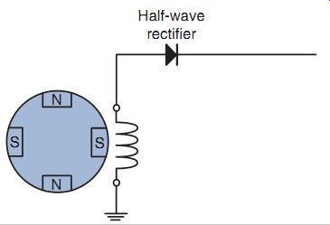
FIG. 12 This simplified schematic shows a half-wave rectifier, which
blocks one-half of the AC waveform.
The Battery
Technically speaking, a battery is an electro chemical device that converts chemical energy to electrical energy. For the purpose of our discussion, a battery is a power source and an electrical storage device that supplies uninterrupted energy for the electrical system in the power equipment engine. For example, implements need lights that operate when the engine isn't running. They get the power for this from the battery. Accessories such as clocks and alarms require a battery, as does the electric starter. As the battery discharges because of use, the charging system charges the battery as required. Most modern power equipment engines use 12-volt electrical systems and therefore use 12-volt batteries.
Lead Acid Batteries
Power equipment engine batteries are also known as lead acid batteries. A conventional wet-cell power equipment engine battery consists of a series of cells (FIG. 13). Each cell has positive and negative metal plates and is capable of storing about 2.1 volts of electricity.
The dissimilar metal plates are placed in an electrolyte solution of sulfuric acid and water.
The plates are then insulated from each other with a permeable, nonconductive material, which allows the transfer of ions. The transfer of ions occurs during the discharge and recharge of the battery. The battery produces electricity from a chemical change that takes place between the positive and negative plates in the electrolyte solution (FIG. 14).
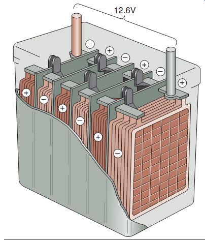
FIG. 13 Batteries consist of a series of cells that contain positive
and negative plates.
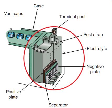
FIG. 14 When the plates of a battery are placed in an electrolyte solution,
electricity is created because of a chemical reaction.
FIG. 15 Electrolyte is measured by its specific gravity or weight as compared to water.
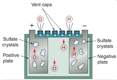
FIG. 16 Sulfation is a normal action of any battery during its discharge
cycle.
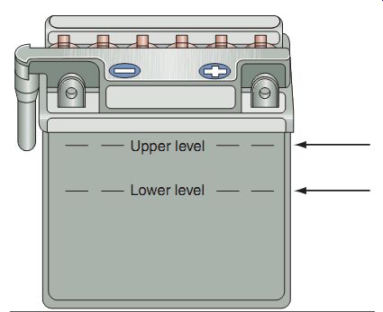
FIG. 17 A battery's upper and lower level markings.
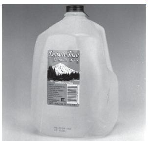
FIG. 18 Distilled water can be purchased at any grocery store and is
the only type of water that should be used to refill a conventional battery.
Also occurring is the change in specific gravity or density (weight) of the electrolyte (FIG. 15). During the discharge cycle, sulfuric acid is drawn from the electrolyte into the pores of the plates. This reduces the specific gravity of the electrolyte and increases the concentration of water. During recharge, this action is reversed and the sulfuric acid is driven from the plates, back into the electrolyte, increasing the specific gravity.
A key point to remember is that during the discharge cycle, lead sulfate crystals are formed on the battery plates (FIG. 16). This is known as sulfating. Although sulfation is a normal reaction with all batteries during the discharge cycle, the battery must be recharged to drive out the sulfuric acid back into the electrolyte, with out which, lead sulfate crystals will continue to develop and become difficult and eventually impossible to break down during a normal recharge cycle. There are two basic types of batteries used in a power equipment engine electrical system: conventional and maintenance free.
Conventional Batteries
The conventional battery has a cap over each battery cell. When you charge a lead acid battery, electrolysis breaks the water down into its components: hydrogen and oxygen gas. Conventional batteries have a vent, usually routed into a tube, to remove the gases produced during the normal battery charge cycle. When current is supplied to the battery, gas is emitted from the plates, and electrolyte temperature increases. This increase in heat causes a loss of water from the battery electrolyte over time. The loss of water and increased heat drastically reduce the life of the battery and, if left uncorrected, will damage the battery beyond repair. With the conventional battery, the water must be replaced as the level drops.
Because a battery is constantly subjected to charging and discharging cycles, the water in the electrolyte is slowly boiled off during normal use. Because of this, you should check the electrolyte level in a conventional battery on a regular basis.
When the electrolyte level drops to a low level, add distilled water until the electrolyte reaches the upper level line on the battery case (FIG. 17).
The volume of acid lost in this process is so small that acid replenishment is never required during the service life of a battery. However, the vent tube must be routed so that it does not discharge near critical parts that are susceptible to acid damage. Use only distilled water when refilling the battery (FIG. 18). Distilled water is water that has virtually all of its impurities removed through distillation. Distillation involves boiling the water and re-condensing the steam into a clean container, leaving the contaminants behind. Tap water contains chlorine, iron, and other elements, which will contaminate the electrolyte and reduce its effectiveness.
When the loss of water due to boiling reaches a point where the plates become exposed, the sulfation process drastically accelerates. This damages the battery and shortens the battery life. Sulfation can occur not only when the electrolyte level is low but also when the battery is discharged for long periods of time.
Remember to always replenish the battery with distilled water only.
Maintenance-Free Batteries
Maintenance free (MF) batteries are similar in design to conventional batteries. The difference is that the positive and negative lead plates in the MF battery use an absorbed glass mat (AGM), which totally seals all of the acid in the special plates and separators. Therefore, you don't need to add water to an MF battery.
Unlike the conventional battery, MF batteries do not have a vent to allow for the escape of excess gases. Instead, they use a safety valve that's designed to open when extreme gas pressures are produced. The safety valve closes and seals the battery when the internal pressure returns to normal.
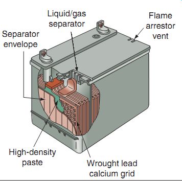
FIG. 19 shows a cutaway illustration of a typical MF battery and its
internal components.
MF batteries require that the included special acid pack (FIG. 20) be installed prior to initial setup (FIG. 21). Some MF batteries come prefilled directly from the manufacturer (FIG. 22).
FIG. 19 The various parts of a maintenance free (MF) battery.
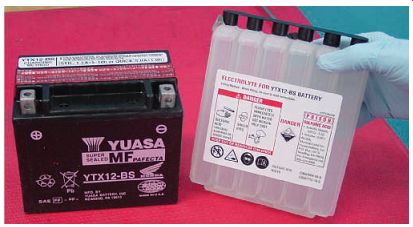
FIG. 20 Most MF batteries come with their own acid pack, which must be
installed prior to initial use.
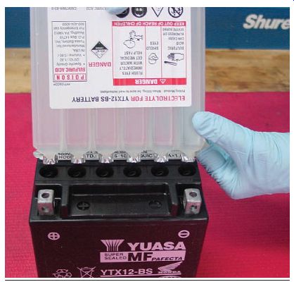
FIG. 21 The acid pack is installed using the manufacturer's instructions.
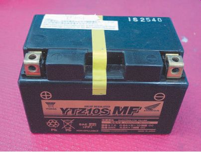
FIG. 22 Some MF batteries come prefilled with acid from the battery manufacturer.
---------
CHARGING SYSTEM OPERATION
Now that you know about the basic components in the charging system of a power equipment engine, let's see how these components work together to charge a battery. Later in this section, you'll learn how to perform various charging circuit tests. Let's now look at an example of a complete schematic (FIG. 23). Note that all the wires are color coded. Oftentimes, the wire colors are abbreviated and a color code box included on the bottom of the schematic.
The schematic may seem quite complex at first, but if you break down the individual electrical system that you're working on, it becomes much easier to read and understand. You can break down a schematic by drawing a block diagram of the system (FIG. 24). Use this figure as we discuss the operation of a basic charging system.
Locate the alternator on the block diagram.
The alternator produces electricity in the form of AC when the engine is running. Notice the three stator leads connected to the alternator.
Current flows through these leads, which are color coded and labeled "Y" (yellow). These wires carry AC from the alternator to the regulator/rectifier unit as the alternator rotor spins past the stator windings. The AC enters the rectifier and is changed to DC, which leaves the rectifier through the R (red) wire. This red wire provides DC to the battery for charging.
The current from the red wire also sends a signal internally to the regulator of the regulator/ rectifier unit. The rectifier and regulator are connected to the common ground by the G (green)
wire. When the voltage reaches a predetermined level, the voltage regulator sends the excess rectified DC to ground to prevent the battery from being overcharged.
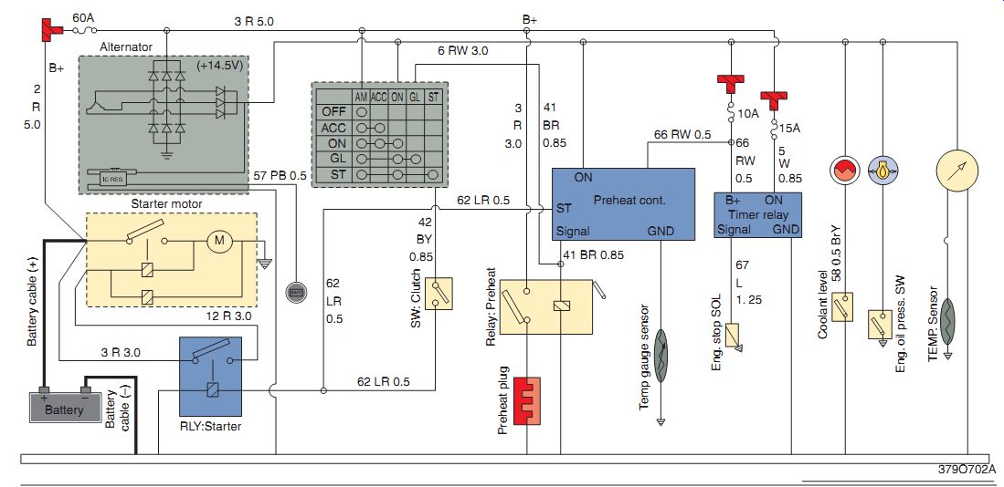
FIG. 23 A complete schematic of a tractor's electrical system.
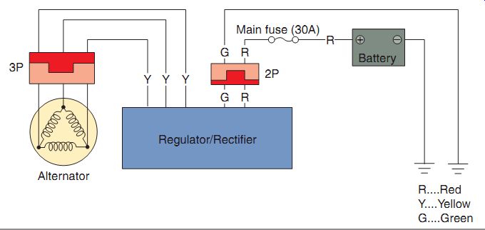
FIG. 24 A block diagram of a charging system.
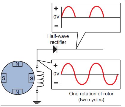
FIG. 25 The half-wave charging system is simple in design as it only
has one diode.
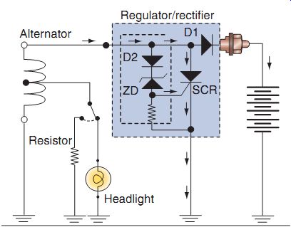
FIG. 26 A half-wave charging system with a voltage regulator either fully
charges or does not charge the battery at all.
As you can see, by connecting individual components to work together as a system, DC is provided for charging the battery and sup plying power to the lighting system. The AC is changed into DC by the rectifier. The amount of charging current is controlled by the volt age regulator. Each component in the charging system must be kept in good working condition to allow the charging system to continue to function properly. This includes keeping all wiring connections clean and tight fitting to pre vent excessive resistance.
TYPES OF CHARGING SYSTEMS
Now that you understand how a basic charging system operates and can identify the individual components in a charging system, we'll move on to a discussion of the various types of charging systems that are found in power equipment engines. We'll begin with the simplest charging system and then learn about the more complex systems. Remember, all charging systems operate in the same basic fashion; they just have different ways of producing AC. One way that charging systems differ is related to the number of charging coils at the input. The charging sys tem is also based on the needs of the electrical system. More electrical components require a larger output charging system.
Half-Wave Charging System
The half-wave charging system is the simplest charging system. This charging system uses only one "grounded" charging coil, and only one-half of the AC output is actually used.
As shown in FIG. 25, the alternator has two pairs of magnets, and it produces two cycles of AC for each complete rotation (360°) of the rotor (flywheel).
A single diode is used to rectify the AC out put into DC to charge the battery. When the AC flows through the diode, the negative voltage wave of the AC is cut off and the positive volt age wave is passed to charge the battery.
This type of charging system has a low out put, and its small size is best suited for very small implements with small electrical loads. Because of its low-output potential, this charging system isn't used very much anymore.
These low-output systems regulate the DC voltage by the use of a relatively simple half wave regulating system (FIG. 26). In this system, the charging current from the alternator is rectified by Diode D1, the output of which charges the battery. When the AC voltage increases (as the engine rpm increases), the AC wave rectified by Diode D2 goes through the zener diode and enables the gate of the SCR to open. The SCR shorts the AC input from the alternator to ground. Therefore, the half-wave charging system with a voltage regulator either fully charges the battery or does not charge the battery at all. This is the major disadvantage of the half-wave charging system and the main reason that it's not used much any more. You may also notice from the figure that this system uses AC to power the headlight system. When the headlight isn't on, the excess power is sent back to ground through a resistor.
One other type of voltage regulation found in some half-wave charging systems is known as the "balanced" charging system. In this system, the alternator is designed to allow the maximum amount of AC that won't overcharge the battery.
The proper AC level is maintained independent of engine speed. Therefore, the balanced charging system needs no voltage regulator. The complete charging system consists of an alternator, a single diode, and a battery.
Full-Wave Charging System
A full-wave charging system also uses one charging coil, similar to the half-wave system, but instead, uses the full output potential of the charging coil instead of sending one half of the coil's output to ground. Full-wave charging systems are used in some medium-sized power equipment engines. Compared to the half-wave charging system, the full-wave charging system is more efficient because it uses almost all of the alternator's output for charging the battery.
The full-wave charging system uses four diodes to rectify the AC from the alternator (FIG. 27). When the AC input voltage is positive, current flows from the alternator through Diode D1, to the battery, through Diode D2, and back to the alternator, as shown by the red arrows. When the AC input volt age reverses direction, current flows from the alternator, through Diode D3, to the battery, through Diode D4, and back to the alternator, as shown by the black arrows. Operating in this fashion, the AC output of the alternator is converted into a full-wave DC waveform.
The voltage regulation system used in a full wave charging system generally has a voltage feedback line (FIG. 28). The feedback line "tells" the voltage regulator when the battery no longer needs to be charged. The regulator then opens the gates on the SCRs. The SCR shorts the AC input from the alternator to ground and cuts off one-half of the current to the battery; it also has the capability to cut off all the current to the battery if needed.
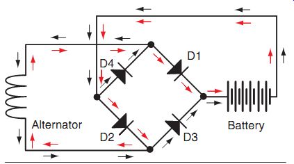
FIG. 27 By using four diodes, both the upper and lower halves of the
AC wave are used and a full-wave rectification system results.
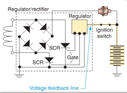
FIG. 28 A full-wave charging system block diagram with a voltage regulator.
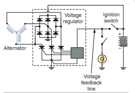
FIG. 29 A three-phase permanent charging system has three coils of wire
at the alternator instead of one, as found in the half wave and full-wave systems.
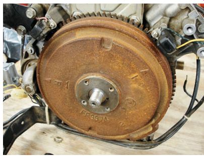
FIG. 30 The alternator for the three-phase permanent-magnet charging
system has the rotor mounted on the crankshaft. The stator is mounted on the
crankcase.
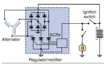
FIG. 31 The regulator/rectifier in a three phase charging system has
six diodes and three SCRs.
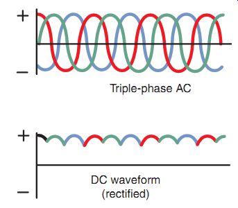
FIG. 32 The waveform created by a three phase charging system closely approximates that of a pure DC output, because three AC waves are produced in a single revolution of the alternator's rotor.
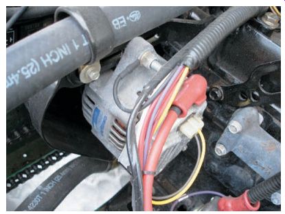
FIG. 33 An excited-field charging system isn't generally located on the
crankshaft, as seen here.
Three-Phase Permanent-Magnet Charging System
The three-phase permanent-magnet charging system is the most widely used system in power equipment engines, because of its large charging potential. This system uses permanent magnets, like the charging systems previously mentioned; however, the three-phase system uses three charging coils instead of one (FIG. 29). The alternator for this type of charging system, just as in the previous two systems discussed, has the rotor mounted on the crankshaft and the stator mounted on the engine (FIG. 30).
The rectifier in the three-phase system consists of six diodes and is connected to the alternator.
The voltage regulation system is the same as in the full-wave system, except that it has the ability to change the charging system from three-phase system to a full-wave or a half-wave system, as the battery approaches its full charge. This is done by independently controlling the gates to the three SCRs, which short the alternator output to ground (FIG. 31). The waveform created by a three-phase charging system (FIG. 32) closely approximates that of a pure DC output, because three AC waves are produced in a single revolution of the alternator's rotor.
Three-Phase Excited-Field Electro magnet Charging System
The three-phase excited-field electromagnet charging system is used in many larger power equipment engines and in engines in which the alternator isn't directly mounted on the crank shaft (FIG. 33). The three-phase electro magnet system differs from the three-phase permanent-magnet system in that it uses an electromagnet in the alternator instead of a permanent magnet to produce the input AC, and also in most cases, it's completely self contained (FIG. 34). This means that all charging system components are housed within one unit. As mentioned previously, there are two types of excited-field systems: brush-type and brushless-type.
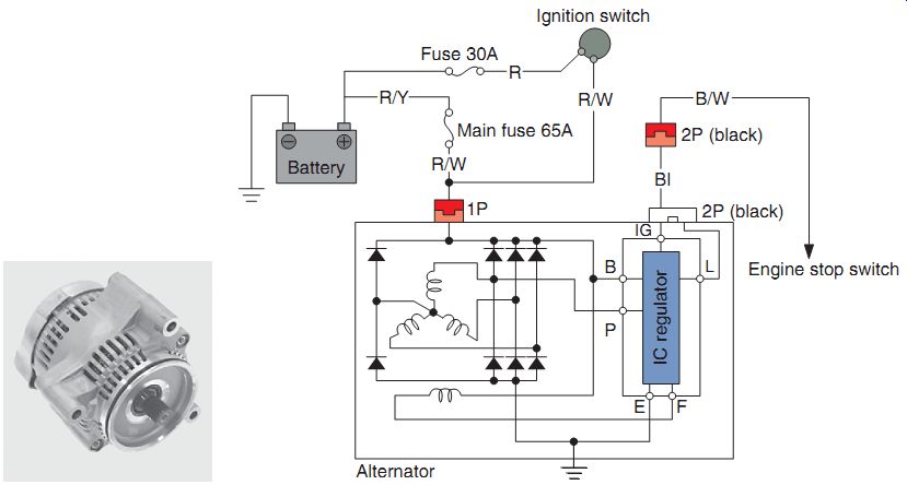
FIG. 34 The three-phase electromagnet system differs from the three-phase
permanent magnet system primarily because the former uses an electromagnet
instead of a permanent magnet to produce AC. Also, in most cases, it's completely
self-contained.
Voltage regulation in the three-phase electro magnet occurs by changing the field coil current to create a stronger or weaker electromagnet. By having more current pass through the field coil, a stronger electromagnetic field is created. Conversely, having less current pass through the field coil produces a weaker electromagnetic field.
The voltage regulator monitors the voltage at the battery and controls the base of the transistor. When the regulator turns the transistor on, the battery feeds current through the ignition switch, field coil, and transistor to ground. The field coils magnetize the rotor and the alternator generates AC as the engine rotates.
The charging system waveform created by the three-phase excited-field electromagnet charging system is the same as for the three-phase permanent-magnet system (see FIG. 32).
CHARGING SYSTEM INSPECTION
Thus far in this section, we've discussed how to recognize the different components of a charging system in a power equipment engine.
We're now going to combine that information and expand on it to help you understand how to inspect for problems found within a charging system.
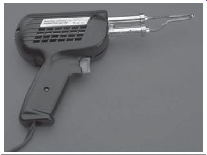
FIG. 35 A typical soldering gun.
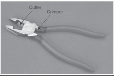
FIG. 36 Cutting pliers with a wire crimper.
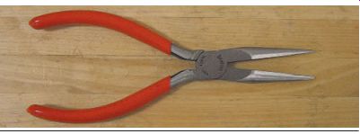
FIG. 37 Needle nose pliers.
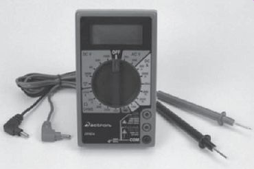
FIG. 40 A typical digital multi-meter.
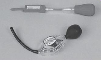
FIG. 41 Two types of hydrometers.
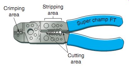
FIG. 38 Wire striper/crimping pliers.
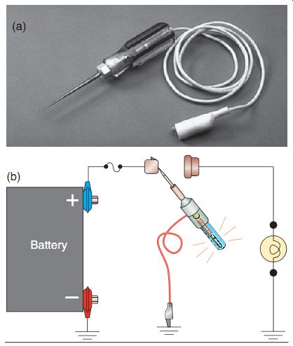
FIG. 39 (a) A typical test light; (b) circuit diagram of a test light in use.
Hand Tools for Electrical Work
The basic hand tools you'll need for most electrical repairs are as follows:
Soldering gun (FIG. 35)
Cutting pliers (FIG. 36)
Needle nose pliers (FIG. 37)
Wire stripper/crimping pliers (FIG. 38)
Test light (FIG. 39)
Multi-meter (FIG. 40)
Hydrometer (FIG. 41)
There are also other electrical system specialty tools that generally are manufacturer specific as well.
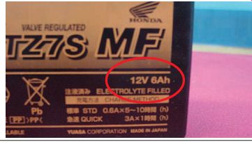
FIG. 42 In some batteries, the amp-hour rating may be easily determined
by looking at the battery cover.
Battery Inspection
First off, be careful when working with a battery. Always wear safety glasses and rubber gloves when working around batteries. Battery acid will destroy clothing, paint, and the like, and could also cause severe burns if it gets on your skin. If you accidentally spill some battery acid, the spill should be washed quickly using water and baking soda, which will help neutralize the acid. After handling battery acid, always wash your hands thoroughly.
Before checking, you should always visually inspect the battery. If there are cracks in the casing, broken terminals, bulging, or other signs of severe damage, such as heavy white lead sulfate on the internal plates, the battery should be replaced.
Next, check the battery cables and ensure they have good contact with the battery terminals. If the cables or terminals are corroded or loose, be sure to clean and tighten the connection. A bad battery connection can cause high resistance, which will interfere with the flow of electrical current. Clean the battery cables and terminals with a wire brush (Be sure to wear safety glasses!). The same goes for any cable connection pertaining to the battery, such as the starter solenoid and ground connectors.
A smear of dielectric grease on the cables and terminals helps prevent corrosion.
The electrolyte in a battery is very caustic.
The condition of a battery is determined by the specific gravity of the electrolyte. When working with a conventional battery, you can use a hydrometer (FIG. 41), which is available from most automotive parts stores. When a battery is new or fully charged, you should get a specific gravity reading of 1.280-1.320 (depending on air temperature). As the battery is discharged, this reading will decrease.
A battery provides DC for operating the power equipment engine. One way of determining the amount of current that can be drawn out of a battery is to know its amp-hour capacity. For example, a 12-amp-hour battery will discharge fully if 1 amp of current is drawn out continuously for a 12-hour period.
Power equipment engine batteries are rated in amp hours. The larger the amp-hour number, the stronger the battery. The voltage does not change in relation to amp hours of the battery.
The battery amp-hour rating isn't always stated within the battery model number. To determine the amp-hour rating in most batteries, you must look on the battery cover. Some batteries will state the amp-hour rating right on the battery (FIG. 42).
Most other MF battery amp-hour ratings will have to be determined using some good old-fashioned math! To determine what the amp-hour rating is on a particular battery, simply look at the standard charge rating (FIG. 43), shown as "STD" imprinted on the battery and multiply that number by 10.
Batteries that are weak or have been out of service for a long time can be recharged using a battery charger. Note that there are two types of battery chargers available.
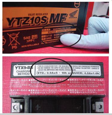
FIG. 43 Some battery amp-hour ratings must be determined by locating
the STD number. Multiply the STD number by 10 to determine the amp-hour rating.
The STD rating may be shown on the front (top) of the battery or on the top
of the battery (bottom).
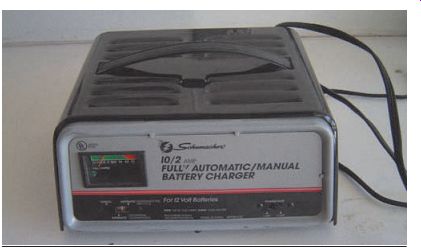
FIG. 44 Automotive-type constant voltage battery chargers are not usually
recommended to charge smaller power equipment batteries.
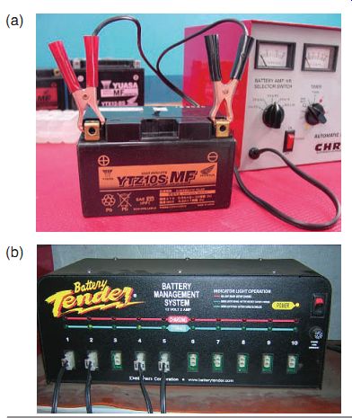
FIG. 45 Most battery manufacturers recommend a constant-current battery
charger over the constant-voltage automotive type. These battery chargers can
be purchased to charge (a) 1 or 2 batteries or (b) up to 10 at once!
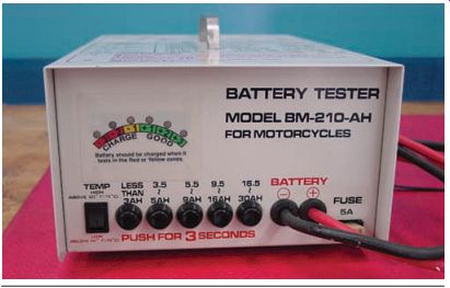
FIG. 46 Load testers are used to test a battery's ability to withstand
high electrical loads. This particular unit shows that it's for motorcycles
but is used on any type of battery that fits within its range.
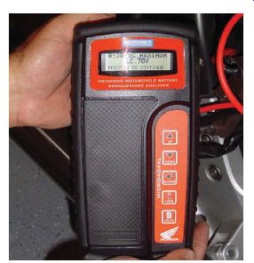
FIG. 47 A battery conductive analyzer describes the battery's ability
to conduct current. This type of test is a more accurate way to determine the
battery's internal condition compared to load testing.
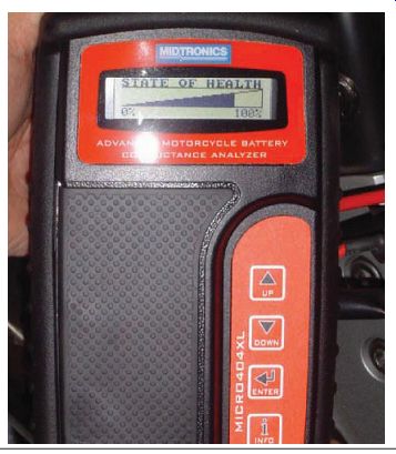
FIG. 48 A battery conductive analyzer has the capability to test the
state of health of a battery.
Power equipment engine manufacturers generally don't recommend the use of automotive-style battery chargers (FIG. 44). Most automotive chargers are of the constant-voltage-variable current type and are slow to charge a battery in a small power equipment engine. However, if you don't shut off the charger on time, a battery can overcharge. It can also be damaged if left connected to the incorrect battery charger for a long time. Remember that batteries produce hydrogen gas, which is explosive. Install the positive battery post first when installing a battery, and always charge a battery in a well-ventilated area.
Instead, most manufacturers recommend the more sophisticated constant-current battery charger-maintainer (FIG. 45), which has advanced features to recover, monitor, and maintain 12-volt batteries. A battery charger- maintainer shuts off the charging process, thereby preventing it from overcharging even if left on the charger for a long time.
In the past and in some cases even today, a battery would be tested for its ability to hold a charge by using a battery load tester (FIG. 46). A load tester tests the battery under a heavy electrical load, such as an electric starter. This test is performed while the battery is disconnected from the implement it's meant to power.
The power equipment engine industry is now beginning to use a tool that has been used in the automotive industry for some time now to measure the health of a battery (FIG. 47). A battery conductive analyzer describes the battery's ability to conduct current. It measures the battery plate surface available in a battery for chemical reaction.
Measuring conductance provides a reliable indication of the battery's condition and is correlated to battery capacity. This type of tester can be used to detect cell defects, shorts, normal aging, and open circuits, which can cause battery failure.
A fully charged battery has a high conductance reading, up to 110% of its internal rating.
As a battery ages, the plate surface sulfates or sheds active material, which lowers its capacity and conductance.
The conductance tester displays the service condition of the battery. It indicates if the battery is good, needs to be recharged and tested again, has failed, or will soon fail. As well as giving a state of charge, this type of tester also shows the overall battery condition, the "state of health" of the battery (FIG. 48).
Once sulfation develops to an advanced state, permanent capacity loss or total failure of the battery occurs. Besides sulfation concerns, many other detrimental actions take place inside the battery while in a discharged condition. The corrosive effect on the lead plates and connections within the battery is greatly increased because of the reduced specific gravity of the electrolyte.
The corrosion of the plates typically result in a gradual reduction in performance, followed by battery failure. The corrosion associated with the inter-cell connectors and the connecting welds in many instances result in sudden battery failure. A corroded connector may have sufficient integrity to support low-drain accessories, such as lights and instruments, but lack the necessary strength to provide the high-discharge current required to start the vehicle. This corrosive effect can also dissolve the lead into solution, which in turn may compromise the plate insulators and result in micro-shorts. Another condition that frequently occurs in a discharged battery is freezing, because the solution in a discharged battery has lower acid content and therefore higher water content.
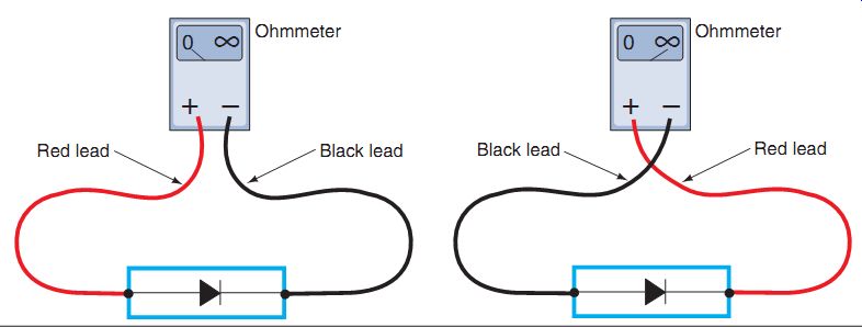
FIG. 49 Testing a diode with an ohmmeter.
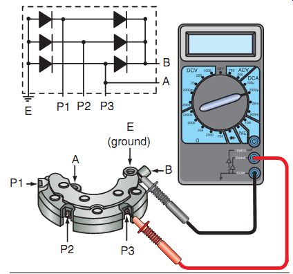
FIG. 50 Testing a six-diode rectifier requires 12 individual tests.
Rectifier/Regulator Inspection
As we've mentioned, electronic voltage regulators and rectifiers have no internal moving parts and must be replaced if found defective.
The main symptoms of a faulty voltage regulator are the following:
The battery discharges.
The battery becomes overcharged.
The lights in the electrical system burn out quickly.
In most cases, to inspect a voltage regulator, you simply run the engine at the manufacturer's recommended engine speed and check for DC voltage at the battery. If the system is overcharging, the regulator is at fault and will require replacement. If the charging system is under charging and all other charging system components have been proven to be in proper working order, the regulator is likely to be at fault.
Rectifiers are relatively easy to test. You can use an ohmmeter to test rectifiers (FIG. 49). Simply connect the ohmmeter to the ends of each of the diodes and check the resistance in both directions. The resistance should be low in one direction and very high in the opposite direction. The specification will be given in the appropriate service manual. A general guideline for testing most diodes is to have 5-40 ohms of resistance in the forward bias direction (where current is allowed to flow) and infinite resistance in the reverse bias direction (where current isn't allowed to flow).
To test the three-phase six-diode rectifier shown in FIG. 50, connect the black probe of the ohmmeter to the ground side of the rectifier (E) and the red probe to P1, P2, and P3.
Record your measurements. Then swap the meter leads and take the three resistance readings again. You have now measured the ground side of the rectifier.
You can now test the battery side of the rectifier by connecting the meter probes to the battery (B) side of the rectifier and test the diodes in the same manner. When you have completed testing, you should have 12 readings consisting of forward and reverse bias measurements for each of the 6 diodes. In most cases, a diode will have between 5-40 ohms of resistance in the forward bias and show infinite resistance in the reverse bias.
Alternator Inspection and Testing
The function of the alternator is to produce electricity that can be used to charge the battery and supply current for other electrical system accessories such as lights. As you learned before, the principal parts of an alternator are the rotor and the stator. Permanent magnets or electromagnets are attached to the rotor and rotate when the crankshaft rotates. Rotors are positioned so that the magnets closely pass the stator coils. As the magnets pass the coils, electricity is induced in the coils.
Problems seldom occur with alternators because they have few moving parts. Servicing is generally not required except on brush type excited-field alternators. If a problem does occur on an alternator, the problem may be due to a faulty stator coil. You should be aware of possible stator coil failures such as:
Open stator wire. If the stator wire is open, there is no AC output; therefore, the battery will not charge. In this case, an ohmmeter will indicate no continuity (infinite resistance) between the terminals being tested.
Shorted circuit. Diagnosis of a shorted circuit is a bit more difficult. The symptom may simply be poor AC output performance or low AC output when the engine is hot. Vibration or shock can be the cause of such problems.
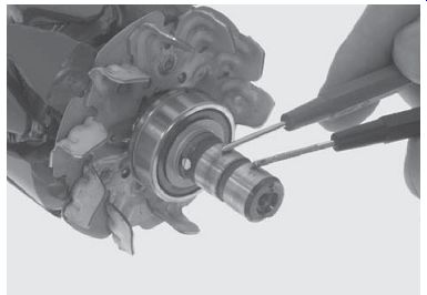
FIG. 51 Testing the field coil resistance by measuring the resistance
through the slip rings.
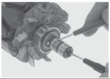
FIG. 52 Checking for a short to ground.
Rotors
Rotors must not contact the stator coils as they turn. Therefore, care should be taken to ensure that the rotor is correctly positioned on the crankshaft. If the rotor is loose or crooked, it will wobble and damage the stator coils.
Rotors don't require service and rarely fail; however, care should be taken to prevent the loss of magnetism on permanent-magnet charging systems, which can be caused in several ways, such as:
- Dropping the rotor
- Hitting the rotor with a hammer (e.g., to remove it)
- Allowing the rotor to come into contact with another magnetic field
Heat and aging are other factors that can cause rotors to lose their magnetism. If the magnets on the rotor are weakened for any reason, you should replace the rotor. Keep in mind, however, that there are no specifications given to tell you how much magnetism a magnet should have. Therefore, you should be aware that low rotor magnetism is the cause of a weak charging system if all other tests indicate that the charging system is working properly and yet the battery does not come to its full charge.
Excited-Field Electromagnet Coil Inspection
Excited-field electromagnet coils can be inspected by measuring the field coil resistance.
To measure the coil resistance, set an ohmmeter to the R1 range. Connect the test leads of the ohmmeter to the slip rings (FIG. 51). If the meter doesn't read as specified in the service manual, replace the component. Coil resistance should normally be about 4 ohms. Also, check to make certain that there is no short to ground at the excited filed by testing the slip ring to the end of the rotor shaft (FIG. 52).
Stator Inspection
The stator can be tested measuring the coil resistance. Set an ohmmeter to the R1 range and connect the test leads between each of the sets of stator coil wires (FIG. 53). The stator coil resistance should be less than 1 ohm for each coil.
Next, verify that there are no shorts to ground by setting the ohmmeter to the highest range.
Measure the resistance between the stator coil core and each coil winding. The reading should be infinity. If there's a short, the stator is defective and must be replaced.
Another test on the stator can be made with the engine running. Set your multi-meter to measure AC voltage and connect the meter to the output of the alternator (FIG. 54). As the engine speed is increased, the AC voltage will increase generally to at least 20 volts AC at each connection point with the stator disconnected from the rest of the electrical system.
When checking the continuity of a stator, remember to isolate the stator from the rest of the electrical system by disconnecting it.
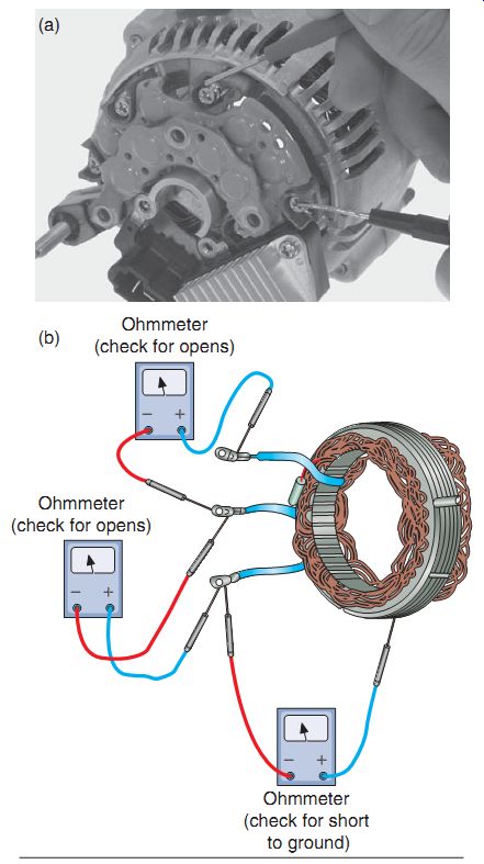
FIG. 53 (a) Checking for stator resistance on an actual alternator and
(b) an illustration of the main tests to verify that a stator is working well.
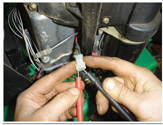
FIG. 54 Testing the stator for AC voltage at the alternator with the
stator disconnected from the rest of the electrical system.
DC ELECTRICAL CIRCUITS
When electric current leaves the battery of an electrical system in a power equipment engine, it travels to various electrical components, both AC and DC. In this section, we're going to discuss the various DC electrical circuits found in power equipment engines. We'll give a brief description of each circuit and show how it can be thought of as a separate electrical subsystem.
The systems that we're about to discuss have four properties in common:
Each is powered by the battery.
Each is operated by a switching device.
Each must complete its circuit to operate.
Each has a load device to create resistance in the system (lights, horn, etc.).
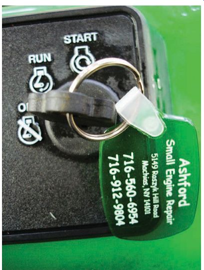
FIG. 55 A properly working key switch will show a complete connection
in one position and an open connection in the other.
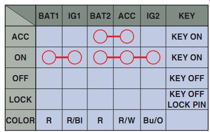
FIG. 56 Many switches have multiple uses for different positions.
Switches
Switches are designed to open and close an electrical circuit. If a switch is defective, it must be replaced. You can check a switch using an ohmmeter. The ohmmeter should indicate continuity (a complete connection or 0 ohms) when the switch is in the On position and should indicate infinite resistance when the switch is in the Off position (FIG. 55).
Some switches have more switch positions and leads than the simple on/off type of switch.
These switches generally have a switch matrix shown in the power equipment engine electrical schematic, similar to that shown in FIG. 56.
A switch matrix shows you the switch positions and the switch leads that should have continuity for each position.
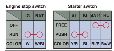
FIG. 57 In this illustration, the engine stop switch is connected when
in the On position, and the (electric) starter switch creates an open to the
headlight (HL) when it's being pushed.
This allows maximum current to be available for the starter motor to start the engine.
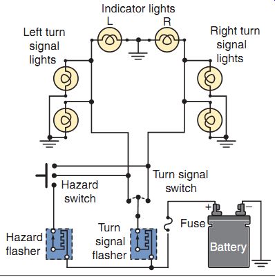
FIG. 58 A typical turn-signal and hazard lighting system block diagram.
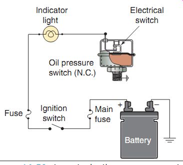
FIG. 59 A typical oil-pressure warning light circuit.
Headlight Circuits
The headlight is turned on whenever the ignition switch is in the On position, but is sometimes momentarily turned off as the electric starter motor is activated. The purpose of this is to allow maximum current flow from the battery to the starting circuit. The headlight is momentarily turned off during starting by the starter switch. When the starter button is pressed or key is turned, the starter switch opens a set of contacts in the lighting circuit (FIG. 57).
Turn-Signal and Hazard Relay Circuits
Turn signals and hazard lights would be found on larger implements such as tractors and machines that may need to be driven on highways at times. FIG. 58 shows a typical turn-signal and hazard relay wiring diagram. The diagram illustrates the system as it would be with the turn signal and hazard switches in the Off position.
When the turn-signal switch is turned on (either left or right), power flows from the battery, through the turn-signal relay, through the L (left) or R (right) switch contacts, and through the left or right indicator and signal lights to ground.
When the hazard switch is activated, power flows from the battery, through the hazard switch contacts, and through both the left and right indicator and signal lights to ground. The hazard relay and turn-signal relay are special circuits that open and close to make the lights flash.
Warning Lights
FIG. 59 shows a typical oil-pressure warning-light system used in a four-stroke engine. If the engine oil pressure falls below a specified level, the oil-pressure switch "senses" it and turns on the warning light. When the oil pressure is too low, the switch provides a ground to turn on the indicator. When the oil pressure is satisfactory, the oil-pressure switch removes the ground connection and the light turns off. Oil-level indicators work in the same fashion by closing the circuit when the oil level is low, causing the warning light to come on.
When there is enough oil in the engine, the circuit is open, which shuts the warning indicator light off.
Summary
The purpose of a charging system is to replenish the voltage in a battery as it's used when the power equipment engine is running.
The alternator generates AC voltage. The rectifier changes the AC into DC. The battery stores the DC voltage, and the voltage regulator controls the voltage being sent to the battery to prevent overcharging or under charging of the battery.
There are three basic types of charging systems used in power equipment engines: half wave, full wave, and three phase.
There are three key requirements needed to produce AC voltage: a magnetic field, a conductor (coils of wire), and motion.
An alternator is used to generate electricity in a power equipment engine and has two main components: the rotor and the stator. The rotor has a series of magnets and rotates either inside or outside the stationary windings of the stator. The stator consists of sets of coils, which are used to produce power for the power equipment engines electrical circuits and to charge the battery.
A rectifier is required to convert the AC from the alternator into DC that is needed to charge the battery. Depending on the type of charging system being used, the rectifier uses a diode or a group of diodes to convert the AC into DC by allowing AC to flow in only one direction.
It's important to understand that block diagrams are often used to separate an electrical subsystem from the rest of the power equipment engine. This is done by drawing out the specific components in the system in question using the complete schematic as a starting point.
QUIZ
1. What is used to generate AC in a power equipment engine?
a. Alternator
b. Rectifier
c. Battery
d. Thyristor
2. Resistance of an isolated component can be quickly checked using a(n)
a. AC voltmeter.
b. ammeter.
c. DC voltmeter.
d. ohmmeter.
3. In a permanent-magnet alternator, the magnets are attached to or are part of the
a. countershaft.
b. crankshaft body.
c. rotor.
d. stator.
4. What device is used to control the rate of charging to prevent undercharging or over charging the battery?
a. Diode
b. Voltage regulator
c. Resistor
d. Rectifier
5. How many cells will a 12-volt power equipment engine conventional wet-cell battery have?
a. 2
b. 3
c. 6
d. 12
6. What device is used to convert AC into DC?
a. Voltage regulator
b. Resistor
c. Rectifier
d. Battery
7. A charging system that uses the complete AC waveform from a single charging coil is called a -- charging system.
a. half-wave
b. three-phase permanent-magnet
c. full-wave
d. three-phase electromagnet
8. Which of the following is potentially the most powerful type of alternator?
a. Excited-field electromagnet
b. Alnico inner-rotor
c. Permanent magnet
d. Current limiter
12. The two main components of an alternator are the
a. rotor and flywheel.
b. regulator and rectifier.
c. rotor and stator.
d. motor and starter.
13. Another term to describe a voltage regulator is
a. current limiter.
b. rectifier.
c. inverter.
d. thyristor.
14. What device is used to detect a short between a stator coil winding and the core?
a. Ammeter
b. Ohmmeter
c. Converter
d. Voltmeter
9. What can be used on a battery acid spill to help neutralize it?
a. Distilled water
b. Motor oil
c. Baking soda
d. Sand
10. White crystal deposition on battery plates is known as
a. chalking.
b. sedimentation.
c. cracking.
d. sulfation.
11. When AC is changed to DC, it's known as
a. rectification.
b. mutual induction.
c. electromagnetism.
d. chemical reaction.