AMAZON multi-meters discounts AMAZON oscilloscope discounts
Goals:
- Understand the importance of engine problem diagnosis.
- Know the differences between the two types of top ends in four-stroke power equipment engines Identify the various components in a four-stroke power equipment engine
- Understand the importance of inspecting the various components of the four-stroke power equipment engine for damage or wear
- Understand the proper procedures to measure the various components of a four-stroke power equipment engine
- Recognize common bottom end engine failures in a four-stroke power equipment engine
- Recognize the importance of bench testing a power equipment engine prior to completing reassembly
- Understand the importance of properly breaking in a power equipment engine
=================
INTRODUCTION
The vast majority of modern power equipment engines are of the four-stroke design. The inspection of the components in a four-stroke power equipment engine top end and bottom end is a process by which the parts of the engine are removed, cleaned, inspected, and measured.
The disassembly and inspection of four-stroke engines are tasks you'll perform often in your job as a power equipment engine technician.
An engine may be disassembled to make needed repairs or to complete the first step in a complete engine rebuild.
It's important to understand how to disassemble the engine right down to the crankshaft.
It's also important to know how to inspect the various engine components, do any necessary repair work, and reassemble the engine correctly.
During a typical rebuild, the engine is restored to a like-new condition. This section introduces you to the procedures used to inspect the four stroke engine components. The procedures that we'll discuss apply to almost all four-stroke engines (regardless of model or manufacturer). We'll explain how to visually inspect and mea sure the components of the typical power equipment engine. We'll also discuss the tools used in the process and the function of certain engine components. You may wish to review Sections 5-7 to refresh your memory on each of the individual components of the engine.
Repairs to the four-stroke power equipment engine often require that the engine be removed from the implement that it's attached to. The ser vice manual for the particular machine you're working on will inform you if the engine can remain in the chassis or if it needs to be removed.
In this section, we'll discuss two types of engine designs: the L-head, which is attached to a typical lawn mower (FIG. 1), and the overhead valve (OHV) engine, which, in our illustrative example, is attached to a gas-
powered pressure washer (FIG. 2). Most of the components of these engines are similar, with the primary difference being in the arrangement and location of the valves.
DIAGNOSIS
If there is an engine-related problem, before any components are disassembled, the technician must diagnose the condition. Diagnosis, as we know, is the process of determining what's wrong when something isn't working properly, by checking the symptoms. Symptoms are the outward, or visible, signs of a malfunction. For example, a knock is a symptom. The actual cause might be a broken, worn, or malfunctioning part. Of course, this is only an example. To assist with diagnosing a problem, you may need to use other testing equipment to help find the problem.
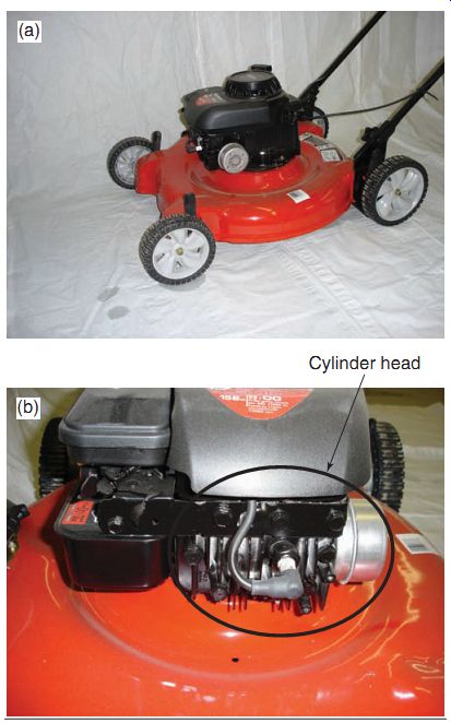
FIG. 1 A typical push-type lawnmower that uses an L-head. Note the shape
of the cylinder head in (b); it can be distinguished by the fact that it has
only i ns across its top.
Often, complete diagnosis can't be confirmed until the engine is actually disassembled. For example, if a four-stroke engine develops a loud noise in the top end (the symptom), an experienced technician may recognize the sound and tentatively conclude that the piston rings are worn out. That would be the diagnosis. The technician wouldn't be able to confirm the diagnosis without disassembling the engine and actually seeing that the rings and related parts are worn or damaged. A compression and leak down test would help to confirm the diagnosis in this particular case.
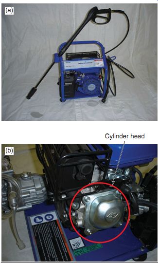
FIG. 2 A gas-powered pressure washer that uses an overhead valve (OHV).
Note the shape of the cylinder head in (b); it has a cover over the valves,
which are built onto the head.
Correct diagnosis of problems is the most difficult and important part of a technician's job. Diagnosis is difficult because the technician often can't see the faulty part before disassembly. Nevertheless, correct diagnosis is important, as the technician must not waste time disassembling and searching for parts that have not failed.
To diagnose problems, experienced technicians mentally divide a power equipment engine into sections. Suppose the engine produces a tapping sound. The technician first listens to hear precisely where the tapping sound is coming from. By working in this manner, the technician inspects each part that's connected to the problem following a logical order of possible malfunctions. We'll get into troubleshooting in more detail in Section 17.
Before beginning any type of engine repair, be sure the power equipment engine is clean.
Dirt or other foreign particles cause damage to internal working mechanisms. Also, always use the manufacturer's service manual during repairs on an engine.
REPAIR PROCEDURES
The procedures in this section, as in Section 11, are general in nature and their purpose is to familiarize you with the types of activities you'll encounter when working on a four-stroke power equipment engine. Always refer to the appropriate service manual for complete disassembly information. The service manual contains all the information to do the job correctly, including detailed instructions for the specific model of power equipment engine, special tools, and service tips. Above all, the service manual contains the appropriate safety information.
As mentioned previously, to allow for a broad understanding of the four-stroke power equipment engine, we'll refer to the two most common types of engines throughout this section: L-head and OHV engines.
Although we'll discuss the process of complete disassembly of engines, be careful not to remove parts that don't need to be removed.
Close inspection of the power equipment engine, or reference to a service manual, can save time spent removing and replacing parts unnecessarily.
When rebuilding any engine, you need to be both patient and precise. Before you begin any repair job, take time to assemble the proper tools and the materials you'll need (e.g., micrometers, valve-related tools, and cleaning solvents). If an engine is to work properly, the measurements involving its piston and valves must fall within the manufacturer's specifications. Be patient and careful as you make the required measurements.
Use proper measuring instruments and record all your measurements accurately on paper to look them over after taking them.
When you disassemble and rebuild an engine, examine the condition of each component.
Check the parts before you clean them. For the most part, this should be a preliminary examination. The as-is condition of the parts can reveal a lot about the operation of an engine.
After you've examined the parts and recorded your observations, clean the parts thoroughly and proceed with the rebuild by measuring and determining which parts need to be replaced and which can be reused.
FOUR-STROKE ENGINE TOP END DISASSEMBLY AND INSPECTION
The components of a typical L-head power equipment engine and OHV power equipment engine are shown in FIGs. 3 and 4, respectively. Removal of the engine from an implement follows a pattern, that is, certain parts must be removed in a particular order. Although we'll not cover the removal of an engine from its implement here, this pattern is similar for most machines. To ensure that the correct pattern is followed, be sure to use always the manufacturer's service manual when removing the engine from the implement. It's advisable to use an assistant when taking the engine out of the implement, whenever possible, as some engines can be quite heavy or cumbersome to move around.
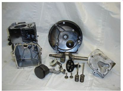
FIG. 3 The components found in a typical L-head power equipment engine.
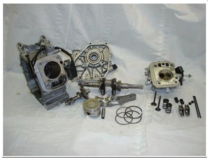
FIG. 4 The components found in a typical OHV power equipment engine.
As there are different power equipment engine manufacturers building four-stroke engines, we'll not discuss how to disassemble the top end of a four-stroke engine. As mentioned in p receding text, the pattern of disassembly procedures is similar for most four-stroke engines. It's strongly recommended that you use the appropriate manufacturer's service manual and follow the procedures therein when disassembling an engine. The purpose of this section is to show you common procedures that you'll see as you work on a four-stroke power equipment engine.
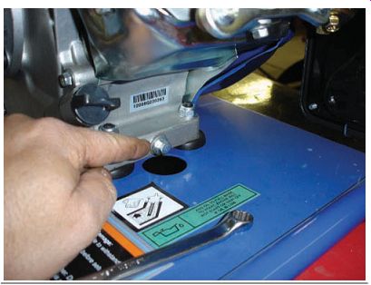
FIG. 5 The oil drain bolt in an OHV power equipment engine.
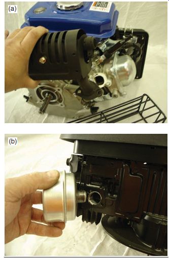
FIG. 6 Removing the mufflers on the engine helps gain access to covers
that will need to be removed. Note that the OHV engine (a) has a bolt on the
muffler, whereas our L-head engine (b) has a muffler that screws on.
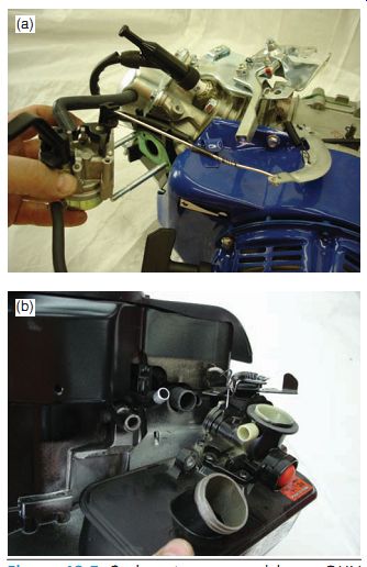
FIG. 7 Carburetor removal in an OHV engine (a) and an L-head engine (b).
Draining Fluids and Removing External Components
Before disassembly of the engine, you should remove the engine oil by draining it out of the engine through the drain bolt provided at the bottom of the engine (FIG. 5). Keep in mind that some engines do not have a drain bolt; in such engines, the oil is drained out of the engine filler by tipping the engine on its side.
Removal of the exhaust system ( FIG. 6) and carburetor (FIG. 7), including all the linkages, should also be done at this time.
Now that the external components have been taken off, you can remove all engine covers to get at the internal engine components that you intend to disassemble and inspect ( FIG. 8).
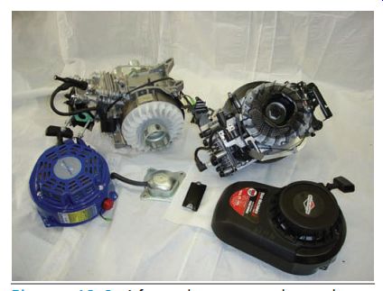
FIG. 8 After the covers have been removed, it's easy to get at the engine's
internal components.
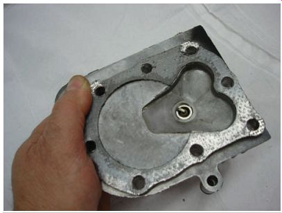
FIG. 9 The L-head engine has no moving parts attached to it. Shown is
the underside of the head.
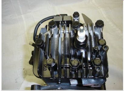
FIG. 10 A close-up of the L-head attached to the engine.
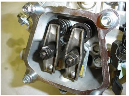
FIG. 11 The top of a typical OHV power equipment engine. Note the valves,
rocker arms, and nuts for adjustment.
Cylinder Head Removal
As we have mentioned, there are two types of engines discussed in this section, the primary difference between them being the design of their heads.
Cylinder Heads in the L-Head Engine Design
The L-head design is quite simple as it acts as a top cover to the engine piston, has no moving parts (FIG. 9), and consists of the combustion chamber. It simply bolts on to the top of the engine cylinder (FIG. 10).
Cylinder Heads in the OHV Head Engine Design
With the OHV design, the cylinder head contains the engine valves as well as the valve-opening device, in most cases rocker arms ( FIG. 11). It also houses ports to allow the fuel mixture into the combustion chamber as well as to allow the exhaust gases to escape. You can see the difference between these two cylinder heads in FIGs. 12a and 12b. OHV engines are more efficient than L-head engines, giving as much as 25% more power.
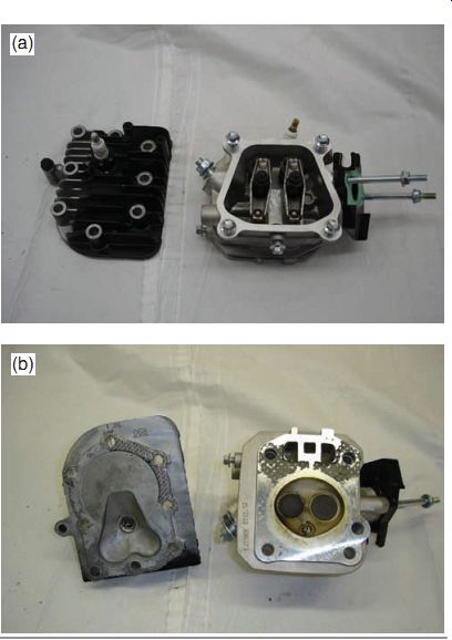
FIG. 12 A comparison of (a) the tops and (b) the underneaths of the L-type
and OHV engine heads.
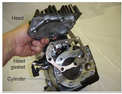
FIG. 13 The head gasket seals between the head and the cylinder.
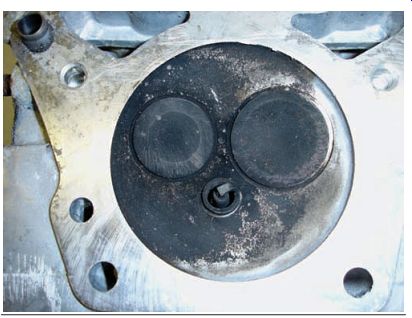
FIG. 14 Carbon buildup is a hard residue that's found often on surfaces
exposed to the burned air-fuel mixture, as seen in this combustion chamber.
Cylinder Head Inspection
The cylinder head, in addition to housing the valves on the OHV engine design, is the component that seals the top end of the cylinder. The head is attached to the top of the cylinder by numerous fasteners. A gasket between the head and the block (FIG. 13) helps create an air tight seal. Because the cylinder head must seal off the cylinder, the head must be in good condition and free of cracks and warpage. Before you can accurately determine the condition of a cylinder head, you should thoroughly clean it with a cleaning solvent.
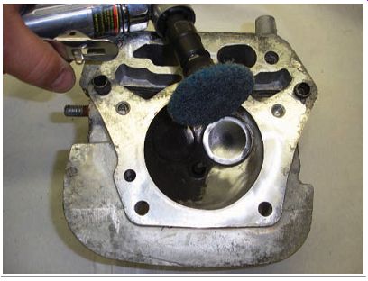
FIG. 15 The combustion chamber after it's been cleaned of the carbon
residue.
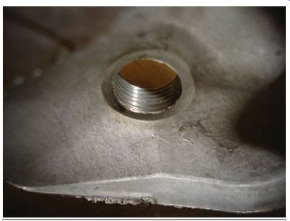
FIG. 16 The most common problem found on cylinder heads is a stripped
spark plug hole. This is something that can be easily repaired when proper
tools are used.
Removing Carbon and Gasket Material Buildup
The combustion area of the head may require some special attention when you're cleaning the head. Carbon buildup, from the combustion process will almost certainly be present on the surface (FIG. 14). Carbon buildup is a hard residue that's often found on surfaces exposed to the burned air-fuel mixture. Because the residue tends to be quite stubborn, you'll probably need a wire or fiber wheel brush to remove the buildup from the cylinder head (FIG. 15). In addition, although most manufacturers use steel gaskets in today's engines, there may be some gasket material left behind when the cylinder head is removed from the cylinder. This left over material can be removed in the same way you would remove carbon buildup. Remember that power equipment engine cylinder heads are made generally of aluminum, which is a relatively soft metal. Be careful that you don't dig into the cylinder head with a scraper or brush when cleaning it. After the carbon residue and gasket surfaces have been scraped off, the head can be cleaned with cleaning solvent.
Checking the Cylinder Head for Damage
After the cylinder head has been cleaned, it can be thoroughly checked for any visible signs of damage. Check for small cracks or other dam age in the area of the combustion chamber. Also, if cooling fins are broken on air-cooled engines, the head may need to be replaced. When working on liquid-cooled engines, check all the water jackets to ensure there are no obstructions. Cylinder heads generally prove to be reliable.
The most common cylinder head problem you'll see is damage to the threads in the spark plug hole (FIG. 16). On all four-stroke power equipment engines, the spark plug is threaded through a hole in the cylinder head.
After the head is removed from the engine, you can easily clean and check the condition of the threads in the spark plug hole. Because most cylinder heads are made of aluminum, the threads in the head can be easily damaged by cross-threading the spark plug. If the threads appear to be damaged, repair them by running a thread tap through the hole or by installing a new threaded insert.
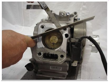
FIG. 17 Checking the cylinder for warpage using a feeler gauge and straightedge.
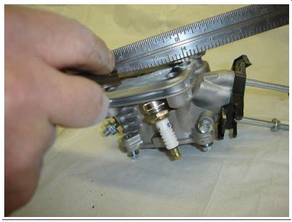
FIG. 18 Checking the cylinder head for warpage using a feeler gauge and
straightedge.
Checking for Cylinder and Cylinder Head Warpage
Having inspected the cylinder head, you can now move on to check for warping of the surface where the new head gasket will be installed. Remember that the cylinder head must seal tightly to the top of the cylinder. The gasket between the head and the cylinder can compensate for some variation in the surface, but not much-the surface of the head must be quite flat. The manufacturer's service manual would tell you the maximum amount up to which the surface of a usable cylinder and head can be warped. The most common method recommended to verify the flatness of the cylinder and head surface uses a straightedge, which is a precision ruler-type tool that is machined flat on its edges. To check a cylinder for warpage, place the straightedge on the cylinder surface on which the gasket will be installed, as shown in FIG. 17. If you notice clearance any where between the straightedge and the cylinder surface, insert the blades of a feeler gauge to measure the amount of warp at that point. The thickness of the blade that fits the clearance is the amount of warp at that particular point.
Because the straightedge is narrow, it should be moved about the surface of the cylinder to check several locations. Measure the flatness in several directions across the cylinder surface.
In most cases, the best indication of the cylinder's flatness is found when the straightedge is placed diagonally across the surface. Generally, the measurement you should use to com pare against the manufacturer's specification is the maximum warp measured at any point on the surface. You should also check the cylinder head to verify that it's not warped, by using the same method as discussed for the cylinder (FIG. 18). Generally, cylinder heads warp more than cylinders.
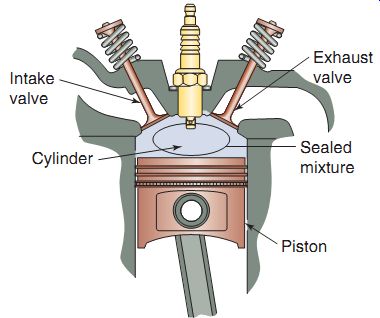
FIG. 19 The intake and exhaust valves must seal tightly to prevent unwanted
flow of gases.
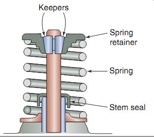
FIG. 20 A typical valve spring and retaining device.
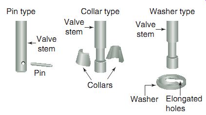
FIG. 21 The three most common retaining devices found on power equipment
engines.
Pin-type retainers are found in older engines, whereas collar-type and washer-type retainers are more commonly found in today's engines.
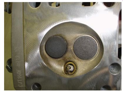
FIG. 22 Power equipment engines are generally of the 2-valve design,
which includes one intake valve and one exhaust valve.
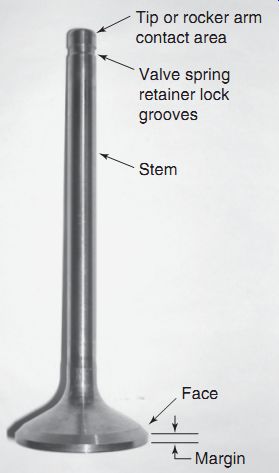
FIG. 23 The five critical areas to look at on a valve.
Four-Stroke Engine Valves
The valves in a four-stroke power equipment engine, as we know, perform two vital functions during engine operation. The intake valve allows the air-fuel mixture to enter the combustion chamber so that the mixture can be burned to produce power. The exhaust valve allows exhaust gases to exit the combustion chamber so that a fresh supply of air-fuel mixture can enter.
The valves must seal tightly when they're closed, so that the mixture in the cylinder doesn't escape during the compression and power strokes (FIG. 19). Therefore, for an engine to operate properly, its valves must be in good condition.
To help the valves to seal, valve springs are used to keep the valves closed (FIG. 20). Valve springs are held in place by retainers ( FIG. 21). There are three types of retainers found on power equipment engines: pin-type retainers are found in older engines, whereas collar-type and washer-type retainers are found more commonly in today's engines. Also, it's common to find a valve seal under the valve spring, which is used to keep oil from entering the combustion chamber. Valve seals can be found on intake or exhaust valves or both.
The basic purpose of a valve spring is to close the valve and ensure that the valve train stays in contact with the cam lobe. Also, it must perform this function under grueling conditions that vary tremendously numerous times every minute. The expected rpm range, camshaft pro file, and cylinder-head design are just some of the criteria that engineers use when choosing the right valve spring for an engine.
Generally speaking, manufacturers of power equipment engines use 2-valve designs (one intake and one exhaust valve, as seen in FIG. 22), but you may also see 3-valve engines (two intake and one exhaust) and 4-valve engines (two intake and two exhaust). Such valve arrangements are used to obtain optimal flow of intake and exhaust gases for the application intended.
There are five critical areas of the typical four-stroke engine valve. The valve areas you'll need to pay close attention to are shown in FIG. 23.
Valves must operate under a variety of extreme conditions. As a result, certain areas of the valve assembly often show signs of wear or physical damage. Because they're located in the combustion chamber, valves can be exposed to temperatures of well over 1,000° Fahrenheit (F) under normal operating conditions.
Heat tends to wear away the exposed surfaces, particularly the valve face. Heat, however, isn't the only problem valves face. Friction between the valve stems and the valve guides produces wear. Keep in mind that each valve must open and close for every power stroke in a four-stroke engine. Because many power equipment engines operate at speeds of 5,000 rpm or more, valves must open and close over 2,500 times per minute. When a valve opens and closes this fast, friction builds up between the valve stem and the valve guide. This eventually leads to wear in the stem, the guide, or both. The rapid movement of the valve also tends to hammer on the valve seat. This hammering action distorts the valve face and the cylinder head valve seat, eventually allowing combustion gases to leak past the valve, even when the valve is closed. For these reasons, all components of the valve assembly must be thoroughly inspected and sometimes replaced or reconditioned as part of any top end engine inspection or rebuild.
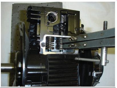
FIG. 24 Many valve springs are removable without special tools, but some
require the use of a valve spring compressor to compress the valve spring to
enable valve removal.
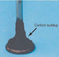
FIG. 25 A valve with excessive carbon buildup.
Valve Inspection
Before a thorough visual inspection can be per formed, the valves must be removed and cleaned.
Although many valve springs can be removed without special tools, some require the use of a valve spring compressor to compress the valve spring to allow you to remove the valve spring holding device (FIG. 24). Be sure to wear safety glasses whenever working on an engine.
Anything that comes in contact with a valve (such as oil, gas, or carbon) tends to get baked onto the valve surface. This can sometimes build up to create large carbon deposits on the valves (FIG. 25). Ordinary cleaning solvents may not have the ability to remove all the carbon on the valves. In most cases, the best way to clean a valve is to use a wire wheel brush. This ensures the removal of all buildup to allow for a good inspection. An ordinary handheld wire brush could be used, but a wire brush on a bench grinder will make the job much easier. After you've cleaned the valves with the wire brush, wash them in cleaning solvent to remove any leftover dirt particles.
Now you can begin the actual visual inspection of the valve. Visually inspect the intake and exhaust valves. This includes inspecting for signs of physical damage and determining if the size of each valve is within specifications. Valves can be damaged because of several conditions. Most often, though, valves are damaged by excessive heat (FIG. 26).
If a valve becomes overheated to an extreme, its edges can melt or its head can crack. If the damage is severe enough, pieces of the valve can actually break off. Common types of valve dam age are shown in FIG. 27. If you notice any of these types of damage, you must replace the valve.
The valve face makes direct contact with the valve seat. The face generally shows uniform wear around the valve and parallel to the mar gin. Carbon can build up on the face and cause the valve not to seat correctly.
Inspect the valve margin for signs of distortion (FIG. 28). The valve margin is the area between the valve's head and the line where the valve face begins. The valve margin is important as it helps the valve withstand the heat in the combustion chamber. If the valve margin is too small, the valve will possibly crack or burn through. It's usually measured using a small ruler or a vernier caliper. When you're checking valve margins, always remember to verify the manufacturer's specifications for the power equipment engine on which you're working.
In addition to measuring the valve margin, you should measure the valve stem, which is the part extending down from the valve's head (FIG. 29). An outside micrometer is used to measure the valve stem's diameter. It's a good idea to measure the valve stem at the top, middle, and bottom. The diameters at all three locations should match the manufacturer's specification.
The valve springs must also be measured for their free length to ensure there's enough seat pressure placed on the valve itself. This measurement is done using a vernier caliper (FIG. 30).
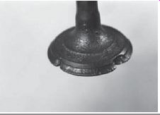
FIG. 26 A common cause of burned valves is excessive heat.
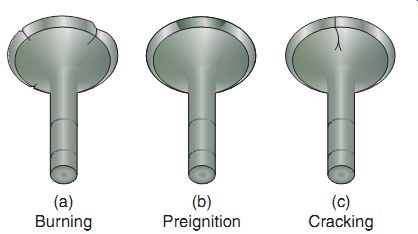
FIG. 27 Common types of valve wear.
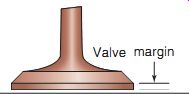
FIG. 28 The valve margin is a critical part of a valve.
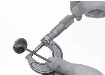
FIG. 29 A micrometer is used to measure the valve stem.
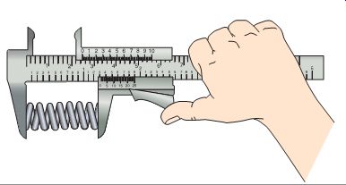
FIG. 30 A vernier caliper is used to measure a valve spring.
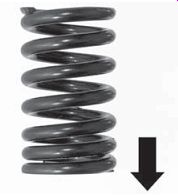
FIG. 31 The valve spring should be installed with the compressed coils
facing the nonmoving part of the engine.
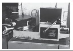
FIG. 32 Valve-refacing machines are not used often now.
Pay close attention to the valve spring coils. In many cases, they're wound in a progressive fashion, meaning that the coils are closer together at one end than at the other (FIG. 31). This allows for a lower rate of pressure being required to initiate the opening of the valve while increasing the pressure as the valve is moved to its fully open position. In most cases, valve spring coils are installed such that the ends with coils closer together are on the surface of the cylinder head or engine block.
Refacing Valves If you inspect valves and find that they're in good condition, they can be reused in the engine. However, all valves will eventually experience wear and distortion from use. However, valve refacing isn't common in power equipment engines. This is because exhaust valves and many intake valves in almost all modern power equipment engines have a coating on the valve face that is used to harden them and increase their longevity. This coating is made of an alloy called stellite. Stellite alloys have astounding hardness and toughness, and are also resistant to corrosion. Stellite alloys are so hard that they're difficult to machine. Therefore, valves that use it are expensive. Typically, a valve using stellite alloy has only a very thin coating of the alloy on its face and often on its tip. Stellite alloys also tend to have extremely high melting points, because of the cobalt and chromium that make the material useful for exhaust valves in today's high-performance engines. Because of the use of stellite, refacing a valve should be carefully considered. A valve that has the hard stellite coating ground off will wear considerably faster than simply replacing the valve.
The process of reconditioning the face of the valve is commonly called valve grinding, or refacing. A machine like the one in FIG. 32 is used for this process.
Most modern engines come with stellite coated valves and, therefore, shouldn't be refaced. If these valves show excess wear, they should be replaced. The appropriate service manual will inform you if the valve may be refaced. It's generally less expensive to simply replace a valve than to reface it.
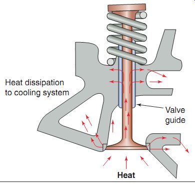
FIG. 33 The valve guide helps to dissipate heat from the valve.
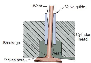
FIG. 34 An illustration of a worn valve guide.
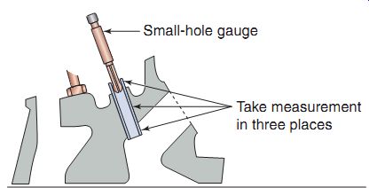
FIG. 35 Measure the guide inside diameter at three locations using a
small-hole gauge.
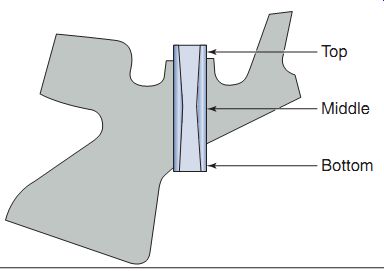
FIG. 36 Most of the wear on a valve guide occurs at the top and the bottom
of the guide.
Inspecting Valve Guides
Now that valves have been inspected and found acceptable, we can move on to valve guides.
These components of the valve assembly are used to position the valves properly in the engine and to guide the valves as they move up and down.
The valve guide's job is difficult. Not only must it keep the valve in position but also it must allow the valve to move freely up and down, and dissipate extreme heat ( FIG. 33). The extreme heat around the valve guide makes it difficult for oil to properly lubricate the guide. If insufficient oil is available for lubrication, excessive friction rapidly wears down the guide. If more oil is present than is needed, the excess oil becomes baked onto the valve stem. The baked-on oil can build up and block the valve openings.
Valve guide wear is a phrase that refers to the amount of clearance between the valve stem and the valve guide. Keep in mind that the valve opens and closes thousands of times each minute. This leads to wear in the valve guide. As the valve guide wears, the valve begins to move slightly side-to-side as it opens and closes. This side-to-side movement, if excessive, can cause the valve to seat improperly and thus fail to completely seal the cylinder. In extreme cases, the side-to-side movement can break a valve (FIG. 34). For this reason, the guides must be checked, and they must be replaced if found to be worn beyond the manufacturer's specifications.
Valve guide wear is determined by comparing the inside diameter of the guide with the outside diameter of the valve stem. Because the inside diameter of the guide is quite small, a small-hole gauge is required to measure that dimension (FIG. 35). As discussed earlier, a typical outside micrometer can be used to measure the valve stem's diameter. The stem diameter is then subtracted from the guide diameter to find the clearance between the stem and guide. Check the guide inside diameter at three locations, top, middle, and bottom of the guide, as the guide will tend to wear more at the top and bottom (FIG. 36). Finally, the calculated clearance is compared with the manufacturer's specifications given in the service manual.
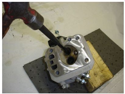
FIG. 37 Driving the guide out from the combustion chamber side of the
cylinder head.
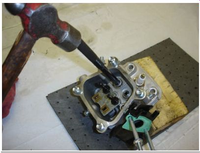
FIG. 38 Installing a new guide from the valve spring side of the cylinder
head.
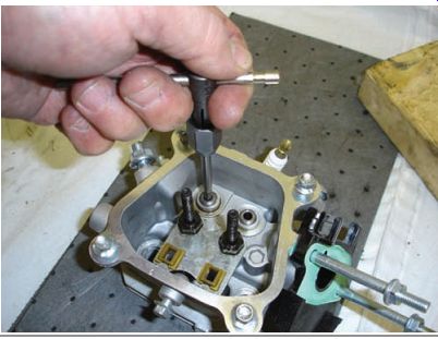
FIG. 39 Using a valve guide reamer is necessary after installing a new
guide.
Replacing Valve Guides
Generally, valve guides are made of soft metals, such as bronze or cast iron, to reduce the amount of friction created by the moving valve stem. Worn valve guides can be removed with a driver and a ball peen hammer and a special driver tool (FIG. 37). These tools are avail able from the power equipment engine manufacturer or a specialty tool maker. When driving out the old valve guide, be sure that the cylinder head is supported so that it won't move. A few small blocks of wood under the cylinder head provide proper support. After you've obtained a driver of proper size, place it on the valve guide from the combustion side of the cylinder head.
Then, use a ball peen hammer or press to knock or push out the guide.
The new valve guide must fit very tightly in the guide bore. Remember that when metals are chilled, they contract (get smaller), and when heated, they expand (get larger). Therefore, to make the task of inserting the valve guide easier, place the guide in a freezer for about an hour, which causes the valve guide to shrink. Also, you may want to heat the cylinder head on a hot plate to allow the head to expand. When the guide has cooled off and the head has heated up, insert the guide into the cylinder head. A special driver is used, again with a ball peen hammer, to install the new guide into the cylinder head (FIG. 38), only this time from the top of the cylinder head instead of from the combustion chamber side, as when the guide is removed.
Because the cold guide has shrunk and the cylinder head has expanded, the guide should fit into the guide bore relatively easily. Be sure to follow the manufacturer's instructions when installing a new valve guide, as procedures vary from one manufacturer to the other.
After you've replaced the guides, you'll need to ream out the newly inserted valve guide, per specifications. A new guide has a slightly smaller inside diameter than is necessary. After the guide has been installed, its inside diameter must be increased to be slightly more than that of the valve stem. The hole in the guide is enlarged using a reamer. A reamer is a long, round cut ting tool with cutting edges along its length. The tool operates much like a drill bit. Unlike a drill bit, however, a reamer doesn't cut on its end; it can't be used to actually drill a hole in a piece of metal. The cutting surfaces of a reamer are along its sides. The tool is used to remove material only along the inside surface of an already existing hole.
To ream out a valve guide, the reamer is inserted into the hole and turned clockwise until it has penetrated the entire length of the guide (FIG. 39). Because of the typical design of the reamer's cutting edges, the tool should always be turned in the clockwise direction (turning it in the opposite direction will dull the edges). Even when you're backing the reamer out of the valve guide, you should continue turning it in the clockwise direction.
The appropriate inside diameter of a valve guide depends on the size of the valve stem.
The service manual for the engine specifies the proper diameter. This allows sufficient clearance for the stem to move through the guide as the valve opens and closes. After a valve guide has been reamed, any metal particles remaining should be removed with compressed air.
Then the area should be washed clean with solvent. Now that you have replaced the valve guide, you must recut or recondition the valve seats.
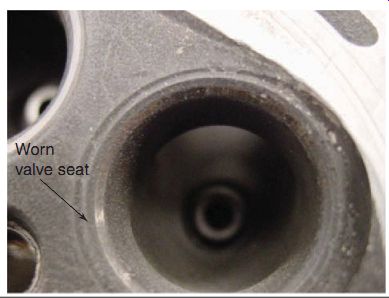
FIG. 40 A worn valve seat will not seal the combustion chamber properly.
Reconditioning Valve Seats
A valve seat is the part of the cylinder head that mates with the valve face. In most cases (especially in OHV engines), a worn valve seat can be reconditioned to get it back into shape (FIG. 40). The seal formed by the valve seat's precise fit with the valve face prevents leakage from the cylinder when a valve is closed.
Due to it's proximity to the combustion chamber, a valve seat, like the valve itself, must be able to withstand high temperatures. A valve seat must also be able to conduct the heat from the closed valve and dissipate it to the engine's cooling system. If a valve seat doesn't help dissipate the valve's heat, the valve would get so hot it could actually begin to melt.
Melting of a valve is often referred to as burning (see FIG. 26). Most often, the exhaust valves are the valves that burn. Exhaust valves get very hot from passing exhaust gases.
An intake valve doesn't get quite as hot because the incoming air-fuel mixture tends to slightly cool it. When a valve closes, the valve face fits closely into the valve seat. As a result, the heat from the valve head is passed onto the valve seat. From there, the heat can be dissipated to the engine's cooling system to the air (in an air-cooled engine) or to the coolant (in a water-cooled engine). The valve seat's ability to dissipate heat is just as important as its ability to provide a proper seal.
In most engines, valve seats are made of a very hard steel alloy. In an aluminum cylinder head, valve seats are usually in the form of inserts pressed into place by the manufacturer.
Because of the extreme heat under which the valve seats operate, the seats, like the valves, become distorted and worn out over time. When the valve face or the valve seat becomes distorted, the sealing surfaces no longer match up; therefore, the valve doesn't seal completely when it's closed. For this reason, valve seats normally need to be refinished during the rebuilding pro cess. The refinishing process, called valve seat refacing, restores the valve seat to a perfectly round shape with a smooth sealing surface.
Also, the valve seat is beveled to match the angle of the valve face. By refinishing the valve seat, you ensure that the valve forms a proper seal when closed.
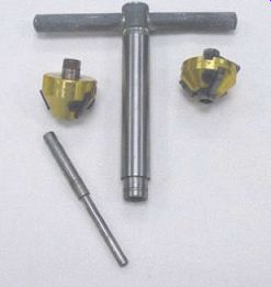
FIG. 41 A typical valve seat cutting tool with its various components.
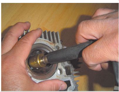
FIG. 42 A valve seat cutting tool in use.
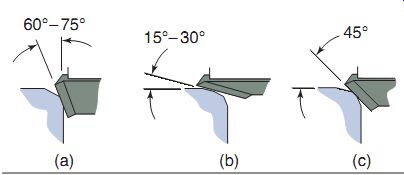
FIG. 43 Typically, three cuts are made to a valve seat: (a) 60°-75° for
below the seat, (b) 15°-30° for above the seat, and (c) 45° for the valve seat
itself. The angle of the valve seat cut is predetermined by the engine manufacturer.
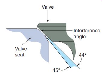
FIG. 44 An interference fit is made when reconditioning valve seats to
allow for better sealing of the valve and valve seat.
Generally, valve seats are refinished using cutting tools of the type shown in FIG. 41.
The appropriate angle for a valve seat is found in the service manual for the engine. The equipment for valve seat cutting is available generally from specialty tool manufacturers.
The valve seat reconditioning tool uses a pilot to position the cutting device and to ensure that the tool remains centered properly. The pilot is simply a round piece of metal that fits tightly into the valve guide. The cutting device has a hole in its center that fits over the end of the pilot. The pilot can thus hold the tool centered in the valve guide. Because a pilot must be inserted into the valve guide to refinish the seat, the valve guide must be in proper condition before the seat is refinished.
After the pilot has been inserted into the valve guide, the cutting device is placed gently over the pilot and in contact with the valve seat (FIG. 42). Note that any sudden impact can damage the edges of the cutter inserts. The cutting tool is then rotated. The rotation of the tool removes metal from the valve seat and refinishes its surface.
There are generally three cuts made when reconditioning a valve seat (FIG. 43). Many consider the angle of the first cut to be a matter of personal preference. The first cut cleans and reconditions actual valve seat area and this cut is generally at an angle of 45°. The second and third cuts are for the area below the valve seat (generally at an angle of 60°-75°) and for the area above (generally at angle of 15°-30°). Some machinists prefer to cut the 45°-angle cut last, instead of first. You should note that the angle of the valve seat is usually about 1° different than that of the valve. This causes an interference, which allows for correct mating of the surfaces once the engine is reassembled and started (FIG. 44).
Thereafter, metal is removed from the valve seat until a smooth, uniform surface appears.
At first, the tool may cut in only a few spots because of the distortion of the valve seat, but as the tool continues rotating, metal continues to be removed until the tool cuts evenly at all points all the way around the valve seat.
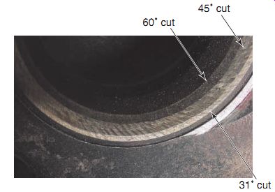
FIG. 45 shows a finished valve seat. Note the different angles at the
three different locations in the figure. The middle bevel (45°) is the actual
seat that makes contact with the valve face.
The width of the valve seat must now be measured and checked against specifications. A seat width scale (FIG. 46), machinist's ruler, or a vernier caliper can be used to measure this dimension. Making the seat too n arrow prevents the valve from sealing properly. Check the manufacturer's service manual for exact specifications.
FIG. 47 shows the ways in which a valve seat can be cut incorrectly.
After cutting the seat and measuring its width, you may find that the valve
seat is too wide, too narrow, too high, or too low. The width can be decreased
by partially recutting the seat with either the top cutter or the bottom cutter.
So, how do we know if we should cut material off the top or bottom of the seat? You can decide on the basis of where the valve face makes contact with its seat, as the seat should be centered on the valve face (FIG. 48). At the same time, you can check on whether the valve face makes contact all the way around its seat. It's important that you finish the job with a proper and complete seal between the face and the seat.
To decide which end of the seat's width you should cut, you can use a technique that involves the application of a blue dye called Prussian blue. This is a special blue dye that can be purchased from most automotive supply stores.
First, remove the cutting tool and pilot from the valve guide. Then, place a coating of the blue dye on the valve face using a small brush or cot ton swab. Insert the valve into the guide and press it in until it firmly contacts the valve seat.
When the face is in contact, apply slight pressure and rotate the valve to a one-quarter turn in the seat. Then, remove the valve and look carefully at the valve face. The dye mark left on the valve seat indicates exactly where the valve face contacts the seat. It should be noted that Prussian blue can be messy! Always keep a rag nearby for cleanup; just a little goes a long way.
If the contact area appears to be closer to the bottom of the valve seat, you should narrow the seat from the top, thus helping to center the contact area. Likewise, if the contact area is closer to the top of the valve seat, you can center the contact area by narrowing the seat from the bottom.
FIG. 45 The three cuts made to the valve seat.
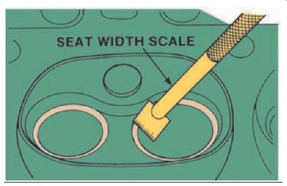
Fig. 46 A seat width scale.
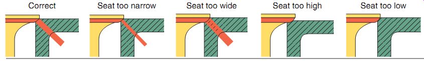
FIG. 47 Incorrect cuts to the valve seat can cause the valve not to seat
correctly, as illustrated here.
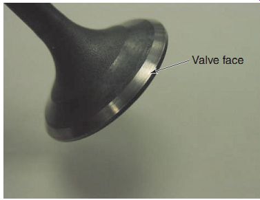
FIG. 48 The valve seat should be centered with the face of the valve.
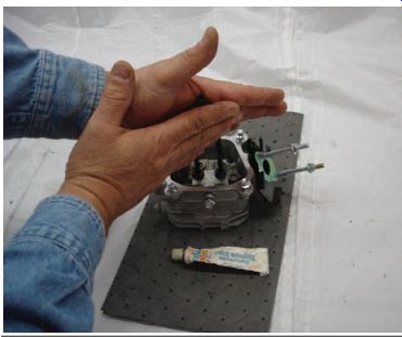
FIG. 49 Using a small hose on the end of the valve makes for a handy valve lapping tool.
Valve Lapping
Valve lapping is the process of mating the valve and the valve seat together to ensure a complete fit between the valve and the valve seat.
Valve lapping produces the closest possible fit between the valve face and the valve seat. As a general rule, valves should be lapped to the seats any time the valves have been removed from the engine, even if they appear to be in good shape and you don't plan on reconditioning the seats.
Most manufacturers recommend that brand new valves should be lapped before installing them into an engine to ensure a perfect seal.
Valves are lapped using a grinding paste or a lapping compound, a substance that feels a lot like ordinary toothpaste, but contains fine, abrasive grains. When the compound is rubbed onto metal, the abrasive grains smooth the metal's surface. The paste is used with all four-stroke engines. Lapping compound is a common product that can usually be purchased from a local automotive parts store. The compound is avail able in versions with grains of varying abrasives.
Usually, a fine-grain compound is used in power equipment engines.
To begin lapping the valves, apply a thin coating of lapping compound to the face of a valve.
When you've covered the contact area, insert the valve into the valve guide and push it down until it makes contact with the valve seat. When installed, each valve rotates within its own seat.
Remember that the abrasive lapping compound is between the valve face and the valve seat. Therefore, when the valve is rotated, the abrasives in the compound wear away the surfaces slightly, thereby mating them to one another.
A valve-lapping stick is a tool sometimes used to rotate the valves. The lapping stick consists simply of a round wooden or plastic shaft with a suction cup on the end. The suction cup is attached to the head of the valve. To help the suction cup stick better, many technicians moisten the cup slightly before attaching it. After you've attached the lapping stick, you can rotate the valve back and forth by spinning the shaft of the tool between the palms of your hands. While rolling the shaft back and forth, apply a moderate downward pressure. This helps the lapping compound to mate the valve and the seat together. Many power equipment engines use valves that are too small in diameter to use a lapping stick. In these cases, install a small piece of rubber hose over the valve stem on the valve spring side of the engine. Then rub the hose between the palms your hands like with the lapping stick while gently lifting the valve into the cylinder head (FIG. 49).
To check the valve seating, remove the valve from the engine and clean away the lapping com pound using solvent and a clean cloth. When the valve is clean, apply a thin coat of Prussian blue dye to the valve face. Then, insert the valve back into the valve guide. Apply a slight downward pressure with your thumb, and rotate the valve slightly. Remove the valve and observe the valve seat. If the blue dye is evenly distributed around the seat, it means that the valve has been properly lapped. If the dye is distributed unevenly around the seat, more lapping compound should be applied and the valve should be relapped or you should consider reconditioning the valve seat.
After all the valves have been appropriately lapped, the valves and their seats should be thoroughly cleaned with solvent and then with soap and water. This removes any leftover lap ping compound. Remember that lapping com pound is abrasive; if it's allowed to get into the working engine, it may do serious harm to the bearings and other vital engine parts. You can test the seal of the valves by inserting them and pouring a liquid (like cleaning solvent) into the port to verify if there is leakage past the valve.
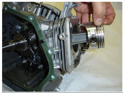
FIG. 50 In a four-stroke power equipment engine, the piston generally
is removed from the top of the cylinder.
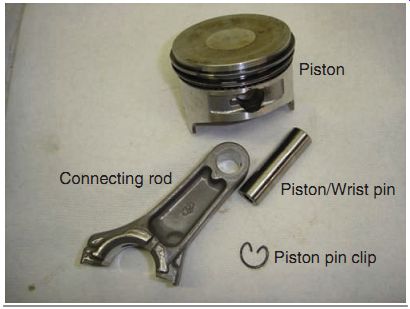
FIG. 51 The piston pin connects the piston to the connecting rod and
is held in place by piston pin clips.
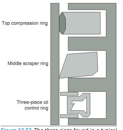
FIG. 52 The three rings found in a typical four-stroke power equipment engine.
Removal and Inspection of Piston and Rings
Before we reassemble the valves of the engine, we'll discuss the removal and inspection of the piston and rings in a four-stroke power equipment engine. To remove the piston, the engine side cover must be removed, as the piston will come out of the top of the engine. To do this, the connecting rod must be separated (FIG. 50). The piston is removed by taking the piston pin retaining clip out using a pair of needle nose pliers, and then by sliding the piston pin out of the piston (FIG. 51).
You'll notice that the typical four-stroke engine generally uses three piston rings ( FIG. 52): an oil ring on the bottom, a scraper ring in the middle, and a compression ring on the top.
Why three rings? The top ring is designed to seal most of the combustion pressure in the top of the piston. The middle ring is used as a compression ring as well but more as a scraper to assist in removing excess oil from the cylinder wall when the piston is moving downward (FIG. 53).
The bottom ring, also known as the oil control ring (FIG. 54), is used to remove most of the oil from the cylinder walls through drain slots in the piston as it's moving downward.
The middle and bottom rings are designed to prevent oil from reaching the combustion chamber. If oil does get to the combustion chamber, the engine will smoke when running.
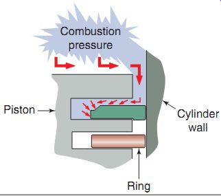
FIG. 53 The top compression piston ring is used to hold compression gases
above the piston, and the scraper ring is used to scrap oil from the cylinder
on its way down the cylinder.
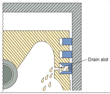
FIG. 54 The oil control ring allows oil to flow back into the inside
of the piston through drain slots.
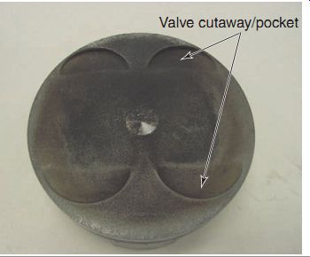
FIG. 55 Cutaways are used to prevent piston-to-valve contact under normal
engine use.
Remember, unlike a two-stroke engine, fuel in the four-stroke engine cylinder is burned without oil; lubrication to the cylinder is sup plied by a separate oil supply system.
Some four-stroke engine pistons have cutaways that are provided for valve head clearance (FIG. 55). These cutaways, or pockets, are designed to allow clearance to prevent the piston from hitting and bending a valve as it opens and closes as the piston goes up and down while the valves are opening and closing.
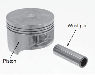
FIG. 56 The piston pin, also known as the wrist pin, connects the piston
to the connecting rod.
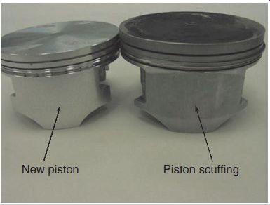
FIG. 57 The piston on the left is new, whereas the piston on the right
has signs of scuffing caused by dirt ingestion through the air-filtering system.
Piston Inspection
As you'll recall, the piston is the cylinder shaped component that moves up and down the cylinder bore. The piston assembly consists of the piston itself, its wrist pin (or piston pin), and the piston rings (FIG. 56). As you're now aware, an engine produces its power by burning the air-fuel mixture in the combustion chamber directly above the piston. Each time the spark plug fires, the air-fuel mixture ignites with tremendous force. The burning process heats the gases, causing them to expand rapidly and forcing the piston down the bore. The piston movement is what allows the engine to perform useful work. During engine operation, the piston has to withstand tremendous force as well as extremely high temperatures. Therefore, as part of the rebuild procedure, you must carefully inspect the entire piston assembly for damage. Be sure to note any markings on the top of the piston that indicate direction of installation.
Checking the Piston for Damage
Start your inspection of the assembly with a visual examination of the piston itself. Check the piston for cracks or any other signs of surface damage.
Look closely in the areas of both the piston skirt and the rings; these areas are the most common sites of damage. Look for scufing or scoring (see Section 10) on the piston skirt (FIG. 57). Scuff markings are wide areas of wear on the piston that usually appear as shiny patches. In most cases, scuffing is caused by inadequate filtering of the air, allowing dirt to be ingested into the cylinder. Score marks are deep, vertical scratches that usually are caused by inadequate lubrication or overheating. Scuffing may or may not be accompanied by score marks.
Scoring and scuffing can be the result of a variety of conditions. In most cases, the marks are created by inadequate filtering (scuffing), excessive friction and heat due to lack of lubrication (scoring), or overloading of the engine.
Under certain extreme conditions, the temperature in a cylinder can approach the melting point, or weld point, of aluminum. These very high temperatures can be caused by a problem in the engine's cooling system or excess friction between the cylinder wall and the piston rings. Excessive friction is often due to improper lubrication.
If you find score marks or scuff marks on a piston, try to determine the cause so you can prevent the damage from reoccurring. This is one of the occasions when you can take advantage of the notes and observations you had made earlier in the disassembly process. During the disassembly, you should have checked to determine if the proper amount of oil was present in the engine or if the air filter was clean and installed correctly. As mentioned in Section 10, notes and observations made at the time of disassembly can help in the troubleshooting process.
Oil Residue
Engine overheating, in addition to causing scuffing and scoring, usually produces a buildup of oil residue on the piston and the rings. You would know that extreme heat breaks down the viscosity of oil and reduces its lubricating ability.
When oil breaks down, it starts to bake onto the engine components, forming a residue that creates oil buildup that after sometime resembles varnish (FIG. 58). This residue can coat the piston rings and eventually cause the rings to stick firmly to the piston. If this occurs, the rings would no longer be able to seal the combustion chamber properly. Therefore, always check to ensure that the rings are free to move on the piston and that both the piston and rings are free of any buildup. The most common way to clean ring grooves is to break the piston ring and use it to clean out the groove.
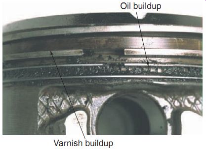
FIG. 58 Oil buildup on a piston can cause the rings to stick.
Examining the Piston Crown
Although the piston skirt is the most frequent site of wear on a piston, you must also carefully examine the piston crown. If you find any dam age, try to determine the exact cause so you can prevent the damage from recurring. Damage to the crown is usually the result of the fuel mix ture burning improperly in the cylinder. If the fuel mixture ignites incorrectly, a violent explosion can result. The concentrated heat created in such an explosion can burn a hole right through the piston crown. Also, the explosion itself can be powerful enough to break right through the top of the piston. The following two terms describe different conditions that cause the fuel mixture to burn improperly.
Preignition . When preignition occurs, the air-fuel mixture in the combustion chamber ignites before the spark plug actually fires.
This may sound strange. How can the mixture ignite before there is spark? The explanation is based on the fact that the burning air-fuel mixture produces a lot of heat. The lingering high temperature in the combustion chamber can cause small carbon deposits to continue to burn, thereby causing the mixture to ignite without a spark (FIG. 59). Preignition can also be caused by excessive compression of the air-fuel mixture. The carbon that sometimes builds up on the cylinder head and piston crown reduces the overall volume of the combustion chamber. The chamber's reduced volume results in an increase in the compression force exerted on the air-fuel mixture. This causes excess heat buildup.
Detonation . In the engine condition known as detonation, the air-fuel mixture fails to burn smoothly. Instead, the mixture begins to burn normally in one area of the combustion chamber and, as the pressure and heat in the combustion chamber increase, it ignites a second time in another area of the combustion chamber (this is also sometimes called "post spark"). Thus, two separate flames burn at the same time in the chamber (FIG. 60), even though they were initiated at different times (these events occur within a split second of each other). This should not be con fused with the use of two spark plugs in an engine, which would create normal combustion because of the fact that the combustion process was initiated when it was supposed to. When the two flames collide, a shock wave is created. The shock wave of detonation effectively hammers the top of the piston and the piston rings. Eventually, this hammering, or detonating, damages the piston and rings.
The key point to understand is that detonation occurs after the initiation of normal combustion.
The most common cause of detonation is the use of gasoline with an octane rating that's too low for the engine. The recommended octane rating for the fuel in a particular engine can be found in the owner's manual and in the manufacturer's service manual for that engine. Detonation may also be caused by incorrect ignition timing. If the ignition timing is too far advanced, the spark occurs earlier than it should. In this case, the fuel mixture ignites and starts to burn when the piston is still rising on the compression stroke. This disruption of the normal burning pattern results in detonation.
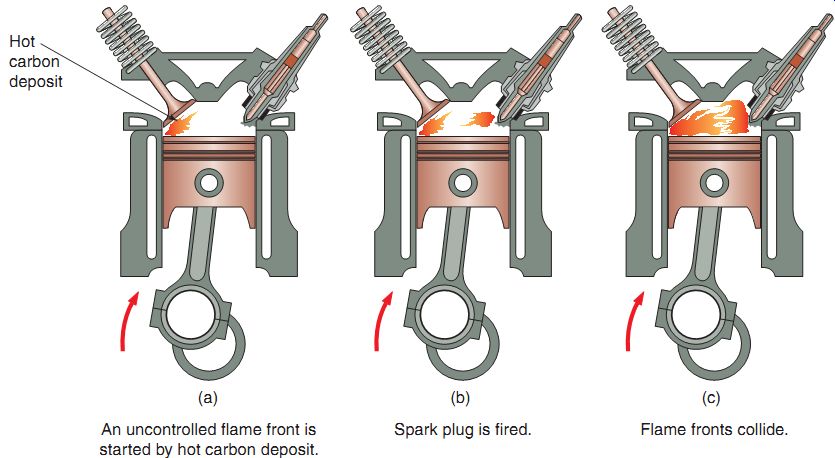
FIG. 59 The phases of preignition.
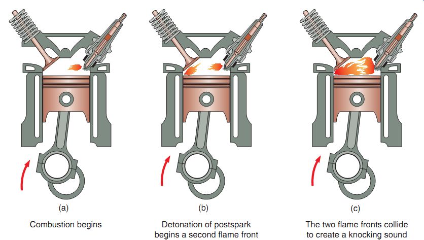
FIG. 60 The phases of detonation.
Piston Ring Inspection
In most cases, piston rings should be replaced when an engine is taken apart. Normally, rings that are reused won't seat in properly, resulting in poor engine performance. You may recall that when new piston rings are installed in an engine, they must wear themselves into position against the cylinder walls to form a tight seal.
Once this process of seating-in has occurred, the rings lose the ability to do so again, that is, if old rings are reinstalled in an engine, they won't be able to conform once again to the cylinder walls and make a tight seal. Without a tight seal, the combustion gases can leak past the rings. This reduces the amount of power the engine can pro duce. In addition, oil from the crankcase seeps past the rings and into the combustion chamber. The engine thus consumes larger amounts of oil. Oil that enters the combustion chamber burns along with the air-fuel mixture. Any oil burning in the combustion chamber is revealed by excessive exhaust smoke as the engine runs.
Worn piston rings are usually bright and shiny at the point where the edge contacts the cylinder wall. Worn rings can also be detected by performing a compression check and an engine leak-down test on the engine before it's disassembled. A compression check is a simple test that measures the amount of pressure produced in the combustion chamber in the compression stroke (FIG. 61a). As discussed in Section 10, the compression is measured with a special gauge inserted in the spark plug hole.
If the piston rings are worn, the gauge displays a pressure reading that's much lower than the manufacturer's specification. The reading is low because, instead of being compressed, some of the air-fuel mixture is leaking past the worn rings and into the crankcase. To ensure a correct compression reading, be sure to hold the throttle open fully while turning the engine over.
This allows the maximum available amount of air into the combustion chamber, which in turn gives the highest possible reading on the compression gauge. Note that some engines have a compression release that will need to be disabled or have a different specification for testing with the compression release attached. Check the manufacturer's service manual for the specifications.
An engine leak-down test (FIG. 61b) is a more comprehensive engine diagnosis test than a compression test as this type of test allows you to measure the percentage of air that leaks past the piston rings and valves. Engine leak-down testers are available from general tool sources.
The leak-down test provides a clear indication of whether or not the combustion chamber is sealing properly. The test involves pressurizing the combustion chamber and measuring the rate at which the air is lost past the rings and valves (or head gasket).
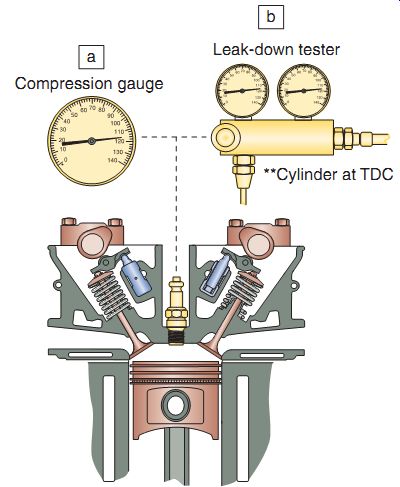
FIG. 61 (a) A compression test can help diagnose a problem before disassembling
a four-stroke engine. (b) An engine leak-down tester gives a better understanding
of where the problem is in a four-stroke engine.
For instance, if the supply of air pressure is 100 pounds per square inch (psi) and the cylinder is able to maintain a pressure of 90 psi, the cylinder is said to have 10% leakage, based on the supply flow rate. But more important than a determination of whether the engine needs repair is to find out more precisely where the problem actually lies. The directions for per forming this type of test will be provided by the tool manufacturer.
Once installed, simply listen to the air-filter, exhaust pipe end, and crankcase filler cap to determine if the intake valve(s), exhaust valve(s), or piston rings are leaking.
Squirting a little soapy water around the cylinder and head mating area will tell you if the head gasket is leaking to the outside atmosphere.
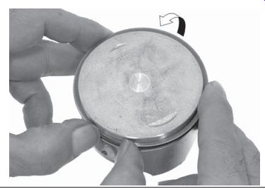
FIG. 62 A technician properly removing a piston ring.
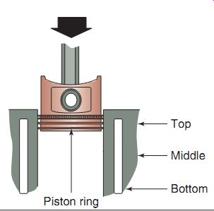
FIG. 63 Use the piston to place the rings correctly into the cylinder
prior to measuring the ring end gap.
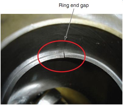
FIG. 64 A close-up of piston ring end gap, which is measured with a feeler
gauge.
Measuring the Piston Rings
Although replacing the piston rings after an engine has been taken apart is good practice, you may wish to measure the piston rings that are already in the engine that you're disassembling.
Before you can measure the rings, you must take them off the piston. To remove a ring, spread the ring open so you can slide it out of its ring groove and off the piston (FIG. 62).
Piston rings are measured by fitting them into the cylinder and then checking the end gap with a feeler gauge. This is done by inserting a piston ring into the cylinder squarely, using the piston as a guide (FIG. 63). After the piston ring is inserted, you can then check for the end gap (FIG. 64) using a feeler gauge. Each piston ring should be measured at the top, middle, and bottom positions of the cylinder. If the readings are different, it's an indication of cylinder taper or out-of-round. The specification for the proper ring end gap is given in the appropriate service manual.
Inspecting Piston Ring Grooves
The ring grooves, cut into the sides of the piston, hold the piston rings in place. The ring lands are the uncut areas between the ring grooves. The ring grooves are actually slightly wider than the piston rings. As a result, the rings can move slightly, or float, within their grooves.
The rings are able to actively conform to the cylinder walls while the engine is operating. As we know, the small space between each piston ring and the bottom side of its groove is called the piston ring side clearance.
The combustion gases forcing themselves onto the piston get down into the ring grooves and leave behind a residue. Therefore, to inspect the ring grooves for excessive wear, you must first clean the grooves thoroughly. When cleaning the grooves, remember that the piston is made of aluminum, a soft metal. Be careful not to dig into the piston and remove any metal, especially along the inner sides of the ring grooves. The most common tool used to clean the piston ring grooves is an old piston ring. Made of a very tough material, old piston rings work well because they fit the ring grooves perfectly and, therefore, won't damage the sides of the grooves. If you use an old ring for this purpose, break it in half to produce a scraper like edge. Then, insert the edge into the groove and scrape the residue out.
FIG. 65 Checking piston ring groove clearance with a feeler gauge.
After the ring grooves are cleaned, the piston can be wiped off and the side clearance for the piston rings can be checked. As mentioned earlier, this dimension is the clearance between the piston ring and the inner side of the ring groove (FIG. 65). This small amount of clearance performs an important function. During the power stroke, the pressure produced by combustion pushes the piston down the bore. Some of the expanding gases are also forced down the side of the piston and behind the floating piston ring. The resulting pressure behind the piston ring forces the ring outward, hard against the cylinder wall, thus helping to better seal the combustion chamber. By allowing the ring to seal better, the proper ring side clearance helps the engine produce more power.
Note that because a small clearance should always be present, a ring tips slightly under normal operating conditions. As the piston goes down the cylinder during the intake stroke, the ring tips and scrapes excess oil off the cylinder wall.
During the compression and exhaust strokes, the piston rises and the tipped ring glides over the oil film remaining on the cylinder wall.
During the power stroke, forces pushing down on the ring cause it to sit squarely, pro viding a better seal and, therefore, better power.
Proper clearance between the piston ring groove and the piston ring can be critical. If the clearance is too large, the ring tips excessively as the piston moves up and down, reducing its ability to seal. The excess movement of the ring on the piston may also cause the ring to break. If the clearance is too small, the ring binds in its groove when the piston heats up and expands.
After you've measured the piston ring side clearance, compare your measurement with the manufacturer's specification. Also, because each ring groove may be worn differently, you should check the side clearance in all of the piston's ring grooves.
Measuring the Piston
After the piston and rings have been visually inspected, you can prepare the piston for measurement.
A typical piston appears to have a simple shape, like a can. However, looks can be deceiving. As mentioned previously, pistons are manufactured with a taper, that is, the diameter at the bottom of the piston's skirt is more than the diameter at the piston's crown. This is due to the varying amounts of material and the different rates of expansion of the material with heat.
Once up to operating temperature, a piston's diameter becomes uniform from top to bottom.
The appropriate manufacturer's service manual shows where to measure the diameter of the piston. FIG. 66 provides an example.
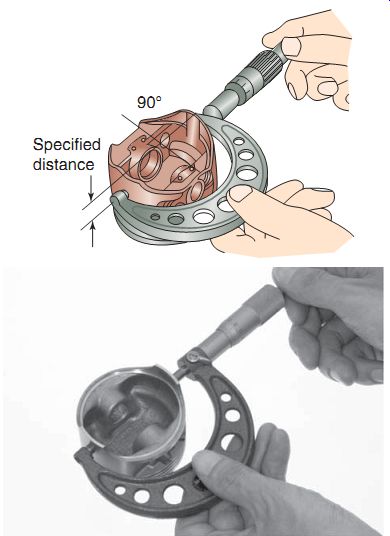
FIG. 66 Engine manufacturers specify where to take piston measurements.
The piston must be measured with a micrometer. It's a good idea to keep track of the piston's actual diameter because you can use that measurement when calculating the clearance between the piston and the cylinder walls. Once you've measured the diameter of the piston, compare your measurement with the appropriate specification or specification range. If the diameter of the piston is outside the specification given by the manufacturer, the piston should be replaced. If the piston is within specifications and shows no signs of damage, you can reinstall it in the engine.
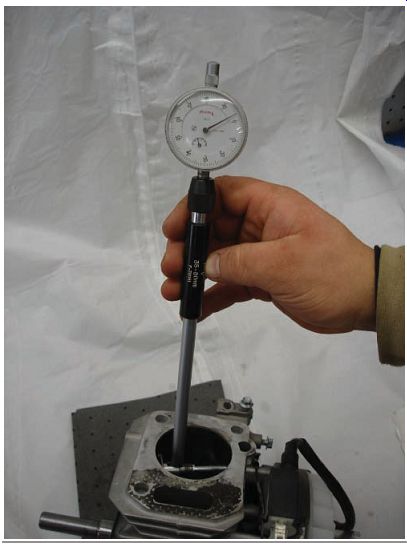
FIG. 67 Using a cylinder bore gauge to measure the inside diameter of
the cylinder.
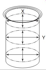
FIG. 68 Points where a cylinder should be measured to determine wear.
Measuring the Cylinder
Now we'll measure the cylinder to deter mine the amount of wear that has occurred on the cylinder walls. Movement of the piston and rings within the cylinder contributes to cylinder wear. The areas of wear are the areas in which the rings travel as well as the areas in which the piston skirt contacts the cylinder walls. Cylinder wear is also caused by the piston rocking on the wrist pin, because of the piston tipping slightly during its travel. Piston rocking can create a noise known as piston slap. Under these conditions, the cylinder wears more on the front and back than on the sides. By front and back, we mean at a 90° angle to the wrist pin.
Cylinder measurements are taken from front to back and side to side. These areas are called the x and y axes of measurement. To measure the cylinder, a cylinder bore gauge (or a telescoping gauge along with an outside micrometer) is used (FIG. 67).
Insert the cylinder bore gauge at a point near the top of the cylinder and rock it back and forth slightly to find the smallest diameter. Move the dial gauge to "0" and use this as your baseline reading. The gauge is then moved to a point near the center of the cylinder and a reading is taken there as well. Finally, the gauge is positioned at the bottom of the cylinder and another reading is taken. This is done for both the x and y axes measurements to determine the cylinder's true ness (FIG. 68). The readings are compared and the difference indicates the amount of wear.
The difference between measurements taken on the same axis (top to bottom) is known as cylinder taper. The difference between the two axes (side to side) is called out-of-round. The taper and out-of-round must not exceed factory specifications for the engine on which you're working. Each model has its own specifications.
If the measurements exceed allowable limits, in many cases, the cylinder may be bored or recut to a new size and fitted with a new and larger piston and ring set. Not all cylinders can be bored; check the appropriate service manual to determine if the cylinder is capable of being bored. Boring a cylinder is a job that requires use of special machine tools and is done generally by a specialist. Boring can be done at most machine shops. Some dealerships do their own boring of cylinders. Cylinder and piston resizing information will be provided in the appropriate manufacturer's service manual.
Measuring Piston-to-Cylinder Clearance
A piston expands as its temperature rises. Because the metal of the piston typically expands more than the metal of the cylinder wall, some clearance must be allowed between these components when both are cold. This clearance is called the piston-to-cylinder clearance, or piston clearance, for short. The proper piston clearance for an engine is given in the appropriate service manual.
If the piston clearance is too small, the piston fits too tightly in the cylinder when the engine heats up, resulting in excessive friction. Friction between the piston and the cylinder can be so great that the piston seizes in the bore. That is, the piston may wedge itself so tightly into the cylinder that it can't move up or down.
You may be able to free a seized piston after the engine cools down again; however, both the piston and the cylinder wall will probably be badly scored and damaged. If the piston clearance is too large, the piston isn't held in place and tends to rock back and forth while the engine is running. This rocking motion can create a knocking noise and may eventually break the piston skirt. In addition, the ability of the piston rings to seal the combustion chamber is greatly reduced.
Determining Piston Clearance
To determine the piston clearance in an engine, you'll need to measure the diameter of both the piston and the cylinder bore. Compare your measurements with the manufacturer's specifications. Then, subtract the outside diameter of the piston from the inside diameter of the cylinder bore.
The result of your calculation is the actual piston clearance. Finally, compare your calculated clearance with the manufacturer's specification.
If the clearance is outside specifications, the piston and cylinder must be resized to make the clearance conform to specification. This method is the most accurate way to measure the piston to-cylinder clearance.
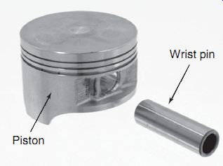
FIG. 69 The piston wrist pin is used to link the piston to the connecting
rod and is also a bearing surface that requires inspection and measurement.
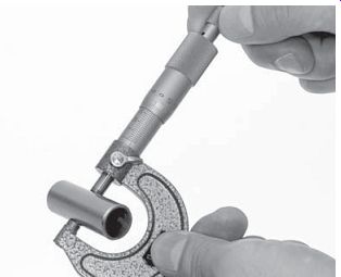
FIG. 70 Measuring a piston pin with an outside micrometer.
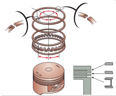
FIG. 71 Piston ring markings should always face toward the piston crown,
and the rings should be placed at angles to one another to prevent compression
gas blow-by.
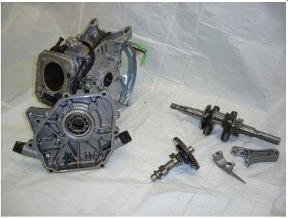
FIG. 72 The primary components of the bottom end of a typical power equipment
four stroke engine.
Inspecting the Wrist Pin
The wrist pin is a cylinder-shaped component of the piston assembly (FIG. 69). It's used to link the connecting rod to the piston. The connecting rod's bearing surface for the wrist pin allows the end of the rod to rotate freely around the pin as the piston travels up and down. The wrist pin must transfer each power stroke's downward physical force from the piston to the connecting rod.
To ensure the wrist pin is strong enough to handle the task, the engine manufacturer makes the pin of very high-quality steel. For this reason, you normally won't see much wear on the pin itself unless there is a lack of lubrication in which case you'll be able to feel and see scoring marks on the pin. To verify that a wrist pin isn't worn, measure the pin's diameter with an out side micrometer and compare your measurement with the specification given in the service manual ( FIG. 70). If there has been a lack of lubrication to the wrist pin, you may need to tap out the pin with a punch and/or apply heat to the piston to expand it. If there is any damage to the piston from lack of lubrication, it should be replaced.
Piston Ring Installation
When installing rings in a four-stroke engine piston, it's important that they be installed with ring markings-if any are placed on the rings- facing upward (toward the piston crown) and their end gaps set at the manufacturer's recommended angle apart from each other (generally 120°) (FIG. 71). If not properly angled, compression gas blow-by may occur.
COMMON BOTTOM END ENGINE FAILURES
When discussing the bottom end of the engine, we refer to all components located below the piston (FIG. 72). In bottom end engine assembly, malfunctions occur most commonly with engine seals, crankshaft, and connecting rod bearings. The following brief descriptions explain these potential problem areas. Being alert to the possibility of problems in one section of an engine while you're performing repairs on another section will help you become a better power equipment engine technician.
Leaking Engine Seals
An engine seal is designed to prevent oil from getting out of a four-stroke engine and leaking between the crankcase and a moving part like the crankshaft (FIG. 73).
A leaking engine oil seal will cause oil to leak out of the engine. Sometimes, this will be a small spot of oil under the engine while the engine is sitting, and at other times, the seal may not leak unless the engine is running. In most cases, a leaking seal will not require that the engine's lower end be disassembled.
Keep in mind that an oil leak may not always be due to a faulty seal. The cause of the leaking may be due to a cracked case or a bent shaft.
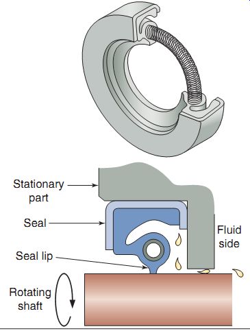
FIG. 73 Seals are used to keep oil in the engine and wherever rotating
parts are found.
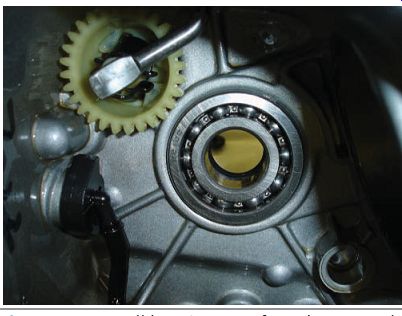
FIG. 74 Ball bearings are found commonly in power equipment engines.
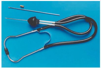
FIG. 75 You may want to use a mechanic's stethoscope to help pinpoint
the location of a bad bearing.
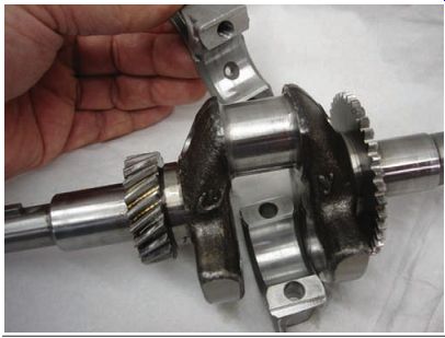
FIG. 76 The bearing surface on connecting rods found in the typical four-stroke
power equipment engine is of the plain bearing design.
Worn Crankshaft Bearings
Crankshaft bearings are used to connect the crankshaft assembly to the crankcase. They require constant lubrication. Many manufacturers use plain bearing surfaces to support the crankshaft. Other than the plain bearing, a ball bearing is the most popular bearing used in the power equipment engine (FIG. 74). A bearing that is failing usually makes a rough growling sound. You may want to use, as in two-stroke engines, a mechanic's stethoscope (FIG. 75) to help pinpoint the location of a bad bearing. Bad bearings may cause excessive up-and-down movement of the crankshaft, or worse, prevent the crankshaft from rotating.
Worn Connecting-Rod Bearings
The bearing surface on connecting rods found in the typical four-stroke power equipment engine is of the plain bearing design (FIG. 76) and allows the connecting rod to pivot freely when the crankshaft turns.
Symptoms of a failed connecting-rod bearing are knocks, vibration, or an engine that can't be turned over (seized up). Any of these symptoms necessitate the disassembly, inspection, and repair of the bottom end of the engine.
FOUR-STROKE ENGINE BOTTOM END INSPECTION
After all the components have been removed from the engine's crankcase, it's time to inspect each one individually to check for damage or wear. Depending on the reason for disassembly, you might think that you should look only for a particular problem while the engine is completely apart. This is far from being correct! While the engine is disassembled, you should carefully inspect all components. Because complete disassembly of the engine isn't common practice, it's important not only to ensure that the job is done right the first time but also to ensure that no existing problems or soon-to occur problems are present. We'll begin this discussion by inspecting the components that are attached to the crankcase.
Inspecting the Engine Block/ Crankcase
The engine block/crankcase should be closely inspected for cracks, loose-fitting bearings, and worn-out fastener-anchoring points. If there are stripped anchoring points, they may be repaired using a special tool and a process that places inserts into the hole (FIG. 77), making the stripped fastener point useful again. These tools should be available at your local hardware store or tool supplier.
Inspecting Engine Seals
Engine seals are located on shafts that rotate and are exposed to the outside atmosphere in a four-stroke engine. Inspect all seals to verify that they're in good condition. Ensure that they fit on the shafts properly. Inspect the seal lips for tears or rough surfaces. The rubber must be live, that is, the lip of the seal must be soft and springy. Most seals have a small coil spring that fits on the outer side of the seal lip. Be sure this spring is in place.
Remove seals by sliding them off the shaft, tapping them out, or prying them out of the crankcase half (Be sure to take caution with the case as damage to the soft aluminum can occur if care isn't taken.). If you remove a seal, you should replace it with a new one. New seals are tapped into place with a mallet or a special seal installation tool (FIG. 78). Be sure to install the seal into the case properly. Incorrect fitting of a seal will cause oil leaks. Generally, the manufacturer's identification number is on the side away from the bearing to be sealed.
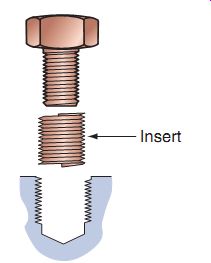
FIG. 77 A typical fastener insert.
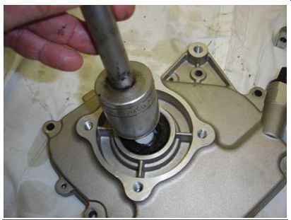
FIG. 78 When installing seals, use a tool that will not damage the seal,
as shown here.
Inspecting Engine Bearings
The two most popular bearings that you'll find inside a four-stroke power equipment engine are the plain bearing and ball bearing. Ball bearings are found generally on the crankcase cover toward the implement side of the engine for extra support of the crankshaft. You can inspect the ball bearing race by hand while it's still mounted on a shaft or if it remains in the crankcase half (FIG. 79). Rotate the inner race by hand and inspect it for any abnormal noise or lack of smooth operation. Visually inspect the races, balls, and rollers. If they show signs of wear, chips, cracks, or damage to the hard bearing surface, you must replace them. The plain bearing surface can be inspected visually for signs of wear and/or scoring from lack of lubrication.
Replace ball bearings if there is any doubt that they're not in good condition. Generally, to replace bearings, first remove the old bearings with the manufacturer's recommended special tools (FIG. 80), if needed. Be sure to remove any clips that may be holding the bearing in place as you could break the crankcase half if any retaining clips are not removed.
Ball bearings are held in the case by a tight fit (or interference fit). Cooling the bearing and heating the crankcase half may be recommended by the manufacturer. Placing cool bearings into a warm case ensures easy installation, as well as a snug fit, when both have returned to normal temperature. This is because the cooled bearings expand as they warm up, and the warmed case shrinks as it cools down. Use the manufacturer's special tools when replacing bearings to ensure that you do not damage the new bearing during installation (FIG. 81).
Plain bearings are used as main bearing surfaces for crankshafts, camshafts, and two-piece connecting rods and use oil pressure from the running engine for lubrication. Plain bearings used in the crankcase are generally machined surfaces and in most cases can't be repaired or replaced if damaged. On the other hand, multi piece connecting rods are measured for the amount of oil clearance they have, using a fine plastic string called Plastigage. If a bearing has too much clearance, the oil pressure will not be high enough for proper lubrication. If too little clearance is present, the component will not spin freely and could actually seize from excess friction and heat.
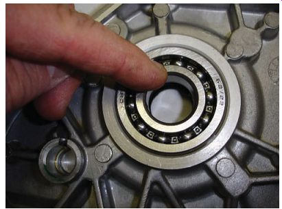
FIG. 79 A technician inspecting the ball bearing race by hand while it's
mounted on the crankcase.
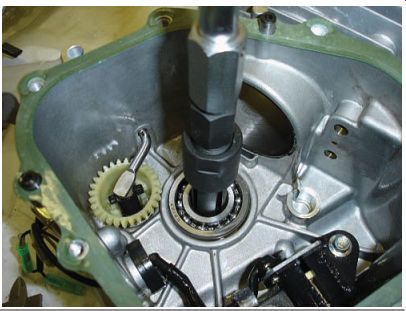
FIG. 80 Removing a ball bearing using a special tool that fits on the
inner race.
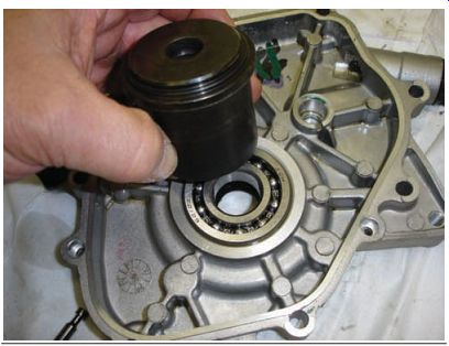
FIG. 81 Using a special bearing-driver tool to install a new ball bearing
will ensure that you do not damage the new bearing during installation.
Plastigage comes in long pieces (FIG. 82) and is available in different colors that have various diameters. Before using Plastigage, you must thoroughly clean and dry the surface to be measured. Place a piece of the Plastigage string on the bearing inside surface (FIG. 83). Then, install the opposite bearing surface and torque to the factory specification. Take the pieces back apart carefully and measure the amount of oil clearance that the bearing has (FIG. 84). You should also inspect the plain bearing visually for signs of wear. Be sure not to turn the crankshaft when checking clearances with Plasti gage as it will not allow for an accurate reading.
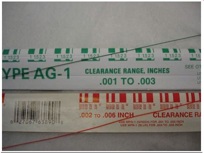
FIG. 82 Plastigage comes in various colors that relate to different sizes.
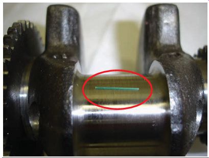
FIG. 83 A small piece of Plastigage placed on the bearing surface to
check the clearance between the connecting rod and crankshaft bearing surface.
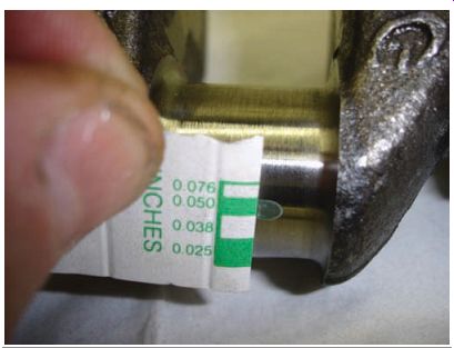
FIG. 84 Measuring the clearance of the bearing surface.
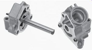
FIG. 85 A typical rotor-type oil pump.
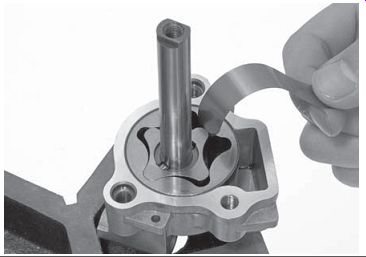
FIG. 86 Measuring the tips of a rotor-type oil pump.
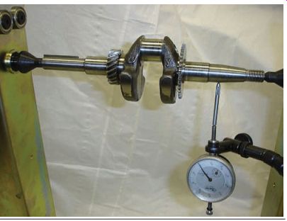
FIG. 87 Measuring a crankshaft to make sure it's not bent, by checking
for run out.
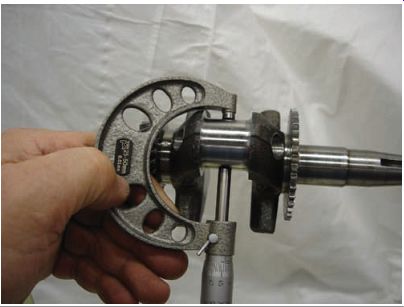
FIG. 88 Measuring crankshaft-bearing surfaces with a micrometer.
Inspecting the Oil Pump
Although many power equipment engines use the splash method to lubricate engine parts, an oil pump is also used in the many four-stroke power equipment engines. Among such engines, the Trochoid-type oil pump, which is better known as a rotor-type pump, is most popular.
The rotor pump consists of a pair of rotors, an inner and an outer rotor (FIG. 85), and is located in the bottom end of the engine. The inner rotor is shaft driven, whereas the outer rotor is moved by the inner rotor and is free to turn in the housing. The lobes on the rotors squeeze oil through passages in the pump body.
As the inner rotor rotates, oil is constantly picked up from the inlet side, transferred, and pumped through the outlet side. Oil pressure is created when the oil is squeezed between the inner and outer rotors. The rotor-type oil pump is capable of creating both high volume and high pressure.
To inspect this type of pump, disassemble and clean the parts of the pump and set the inner and outer rotors into the pump body properly. Measure the body clearance and tip clearance using a feeler gauge (FIG. 86). If all measurements are within the manufacturer's specification, reassemble the oil pump in the reverse order of disassembly.
Inspecting the Crankshaft
A single-piece crankshaft can be inspected and measured after the connecting rod has been removed. One way to ensure that the crankshaft isn't bent is by checking for crankshaft run out (FIG. 87).
Inspect the crankshaft and connecting rod journals closely for signs of scoring or roughness. The surfaces must be smooth. You should also measure the bearing surfaces with a micrometer and check your measurements with the factory specification given in the appropriate service manual (FIG. 88). Crankshafts used in power equipment engines are not generally rebuildable and, therefore, will need to be replaced if the measurements aren't within factory specifications.
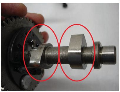
FIG. 89 Camshaft lobes open and close valves, should be inspected visually,
and are measured with a micrometer.
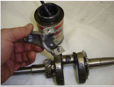
FIG. 90 Using an assembly lubricant on the bearing surfaces is important
to assist with additional lubrication during initial start-up of the engine.
Inspecting the Camshaft
The camshaft is the component that controls the opening and closing of the valves in a four stroke engine. There is one camshaft that drives both the intake and exhaust valves in the typical four-stroke power equipment engine. As the camshaft spins, the cam lobes (FIG. 89) open the valves either directly or indirectly by the use of rocker arms.
When you're rebuilding an engine, the cam shaft should be visually inspected for any signs of damage. Specifically, look for any cam lobes that appear to have surface damage. Also, check the camshaft's ends that are supported on a bearing surface, just as the crankshaft. Look for any signs of scoring or other surface damage.
Power equipment engine manufacturers pro vide a specification for the diameters of each part of the camshaft. Measure those areas using a micrometer and check your measurements against the specifications.
FOUR-STROKE ENGINE REASSEMBLY
Before you begin reassembling any engine, be sure to thoroughly clean every part with a cleaning solvent. When you're prepared to begin the reassembly process, stay organized and keep the engine components separated. This will make you more efficient. Although it's important to use the manufacturer's service manual for any work on a power equipment engine, here are a few common tips to use during the reassembly process of any four-stroke engine.
Installing the Crankshaft and the Oil Pump
Install the crankshaft carefully to ensure that no damage is done to the bearing surfaces. Use engine oil or an assembly lubricant on the bearing surfaces to assist with initial startup of the engine (FIG. 90). When used, the oil pump will generally bolt into the crankcase.
Installing the Camshaft
You should be aware that all four-stroke engines must be adjusted, or timed, so each rotating part is in the proper position, at the proper time, in relation to other moving engine parts. The timing of the camshaft rotation, in relation to the crankshaft rotation, is vital. This is because the camshaft must open the valves and allow them to close at specific degrees of rotation of the crankshaft. The induction and exhaust of gases must take place at specific times in the engine cycle.
The camshaft used in the power equipment engine industry is located inside the engine crankcase. Its rotation is synchronized with that of the crankshaft to open and close the engine valves precisely in relation to the position of the piston and the crankshaft.
Relation Between Camshaft Rotation and Crankshaft Rotation
The timing for the valves to open is determined by the position of the camshaft. This position is indicated by degrees of crankshaft rotation. You already know that there are 360 degrees in a circle. A quarter of a turn is, there fore, equivalent to 90°, half a turn equivalent to 180°, and a three-quarter turn equivalent to 270°. The valves must open and close at specified degrees of crankshaft rotation. The gear reduction ratio between the crankshaft and the camshaft is always 2:1 in a four-stroke engine.
This means that the crankshaft makes two revolutions for each single revolution of a camshaft.
Another way of looking at this relation is that if the crankshaft is rotated 90° (or one-fourth of a complete rotation), the camshaft is rotated 45° (one-eighth of a complete rotation). This relation must remain constant during a complete rotation of the engine or failure will be eminent.
If the timing between the crankshaft and cam shaft isn't correct, valves will hit onto the piston, causing engine failure.
Timing of the camshaft position in relation to the crankshaft position is done by aligning certain marks. However, there are various ways, and various places, where these marks may appear. One of the principal pieces of information you must have for every four-stroke engine is the exact location of the timing marks. Generally, the marks are located on the crankshaft and the camshaft sprocket (FIG. 91). These marks might be lines, dots, letters, or a combi nation of these.
Be sure to check the manufacturer's service manual for the correct cam timing marks and procedures.
Installing the Piston
Install the piston pin through the piston and small end of the connecting rod, making sure the piston's directional arrow is facing in the correct direction. The piston will be installed into the engine from the top of the cylinder with the connecting rod attached (FIG. 92). This is done by compressing the piston rings and sliding the piston into the cylinder. Some manufacturers use piston ring compressors when installing the piston but most pistons can be installed by hand by carefully compressing the piston rings and sliding the piston into place. Always install new piston pin clips on the piston. Attach the connecting rod to the crankshaft by using the proper torque figures given by the manufacturer (FIG. 93)
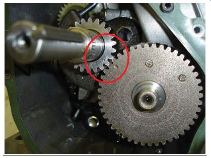
FIG. 91 The camshaft timing marks are located generally on the crankshaft
and the camshaft sprocket.
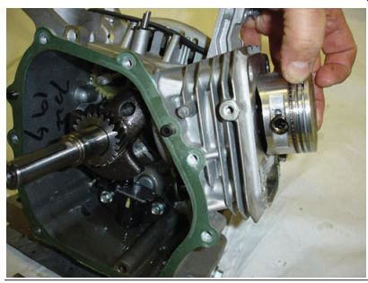
FIG. 92 Installing the piston through the top of the cylinder.
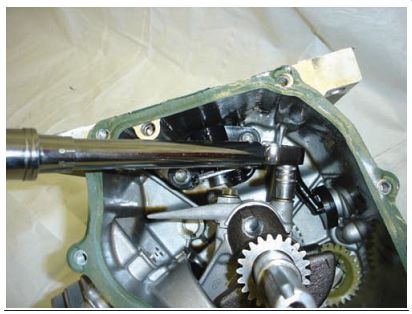
FIG. 93 Using a torque wrench to tighten the connecting rod to the crankshaft
is important.
Installing the Crankcase Cover
When installing the crankcase cover for the engine's bottom end, be sure to use new gaskets and properly torque the cover using the engine manufacturer's recommended procedures.
Installing Valves
Depending on the engine design, the valves may be installed on the cylinder head or on the crankcase/block (FIG. 94). As mentioned earlier in this section, valve springs should be installed so that the narrow pitch of the spring sits on the surface (FIG. 95) of the engine block or the head (nonmoving surface). Always replace valve stem oil seals when the valves are removed, to prevent any chance of oil-seal-related problems. Good valve springs provide adequate seat pressure to allow a tight fit between the valve face and the valve seat to seal the combustion chamber. Proper valve springs also prevent the valve from bouncing on its return to the seat ( especially at high engine speeds) and thus leading to loss of cylinder pressure. Valves are held in place by valve keepers, which should be installed using the manufacturer's instructions.
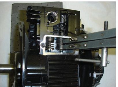
FIG. 94 Using a special valve spring compressor to assist with spring
installation.
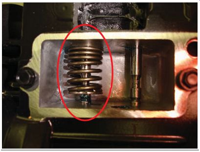
FIG. 95 The narrow pitch of the spring sits on the nonmoving surface
of the engine.
Checking and Adjusting Valve Clearance
It's important to check the clearance between camshaft and valve stem tip during reassembly of the engine. Since the space between the valve and camshaft may have changed by the reconditioning and lapping procedures, the clearances should be measured and compared with the manufacturer's specifications. If valve clearance is incorrect, it will need to be adjusted. There are different adjustment procedures for different power equipment engines. These are discussed in Section 16, which covers maintenance procedures.
There are different adjustment methods used for different valve arrangements. Valve clearance is generally checked when the piston is at top dead center (TDC). At the TDC position in the compression stroke, both the intake and exhaust valves for the cylinder should be completely closed. Generally, valve clearance is greater on the exhaust valve than on the intake valve because the exhaust valve gets hotter, resulting in a higher rate of metal expansion. Valves are adjusted when the engine is at room temperature. Specifications for valve clearance vary with each model of power equipment engine. It should be noted that in some engines, a compression release is used and in these cases, the valve clearance may need to be checked at a different crankshaft position. Be sure to check the appropriate service manual to ensure that you're checking the clearance at the correct spot.
Bench Testing
It's good practice to verify that all components move freely and properly before completing the engine reassembly process. Turn the crankshaft over to make sure it moves freely.
Nothing is more frustrating than finding a problem in the crankcase after you've completely reassembled the engine and installed it into the implement.
Engine Break-In
Most manufacturers recommend that a new (or reconditioned) engine be properly broken-in to ensure that all components are sealing and meshing together properly. With the four-stroke power equipment engine, the time needed to properly break-in an engine varies depending on its use.
During the assembly process, it's recommended that you use the best possible materials and original equipment manufactured parts. Even so, it's necessary to allow the parts to break-in before subjecting the engine to constant maxi mum stress. The future reliability as well as the performance of the engine depends on a proper break-in procedure. The reason for power equipment engine break-in is to optimize the compression seal between the combustion chamber and the underside of the piston, which in turn will minimize pressure loss in the cylinder.
The piston ring seal is really what the break-in process is all about. Piston rings do not seal the combustion pressure by spring tension. Ring tension is necessary only to "scrape" the oil as the piston goes back down the bore of the cylinder.
A typical piston ring exerts less than 10 pounds (lbs) of spring tension against the cylinder wall.
That level of low spring tension can't seal pressures exceeding 1,000 lbs that are created from the combustion chamber gases.
The true sealing of the piston ring to the cylinder wall comes from the actual combustion gas pressure. The gases created by the rapid ignition and burning of the fuel-air mixture in the combustion chamber take the path of least resistance, which means they pass over the top of the ring and get behind the ring to force it outward against the cylinder wall (FIG. 96).
The problem is that new piston rings are far from a perfect match for the cylinder and must be worn in properly as quickly as possible for the ring to completely seal all the way around the bore of the cylinder. If the gas pressure is strong enough and the piston ring is mated correctly with the cylinder, the entire ring will make con tact with the cylinder surface, thus minimizing combustion gas loss and allowing for maximum power in the engine. Many engine builders recommend that a power equipment engine be used as the owner would generally use it, that is, not sustaining high engine rpm for the first 1-2 hours.
These numbers are general and it's recommended that you follow the manufacturer's instructions.
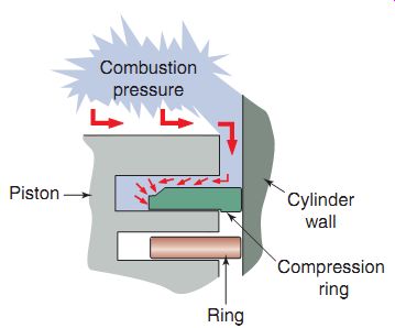
FIG. 96 Shown is how the gases inside the combustion chamber actually
seal the piston ring to the cylinder.
Summary
Many components in the four-stroke engine require careful inspection and measurement.
A visual inspection is critical for successful completion of a four-stroke engine rebuild, as is correct and proper measurement using appropriate tools. As a technician, you must understand the importance of inspecting the various components of the four-stroke engine using the correct and appropriate tools and equipment.
Although a diagnosis may not be confirmed until the machine is actually disassembled, when there is an engine-related problem, the technician must diagnose the condition.
The two primary types of power equipment four-stroke engine top ends are the OHV and L-head.
Common bottom end engine failures in a four-stroke power equipment engine include leaking engine seals, worn crankshaft bearings, and worn connecting-rod bearings.
Plastigage is required to ensure the correct measurement of the bearing surfaces of a connecting rod.
A technician who completes the reassembly process of an engine without bench testing it risks the consequence of the engine not functioning correctly because a component had been installed incorrectly.
Breaking in a newly rebuilt engine correctly is critical for the longevity of the engine.
QUIZ
1. Pistons used in most power equipment four-stroke engines have piston rings.
2. The difference between measurements taken on the same axis (x or y) of a cylinder is called __.
3. The process used to mate the valve and the valve seat together is called .
4. must be installed so the narrow pitch sits on the nonmoving surface of the engine.
5. The valve usually has more clearance between it and the camshaft.
6. Valves are adjusted at room temperature. (True/False)
7. The gear ratio between the crankshaft and the camshaft is ___.
8. Camshafts are timed in relation to the __.
9. The valve seat is part of the
a. valve spring.
b. cylinder head.
c. piston.
d. camshaft.
10. The marks on the piston rings should al ways be installed
a. facing the piston crown.
b. facing each other.
c. facing downward.
d. facing away from the piston crown.
11. To measure piston ring end gap, you use a __.
12. The most common cylinder head problem is damage to the ___.
13. Refacing valves that are coated with stellite
a. is a common practice in the power equipment engine industry.
b. is not recommended.
c. is only occasionally needed.
d. is better than replacing them.