AMAZON multi-meters discounts AMAZON oscilloscope discounts
Goals:
- Understand the importance of engine problem diagnosis
- Understand the necessity of proper engine component inspection
INTRODUCTION
Although becoming less prominent in the power equipment engine industry because of the advancement of four-stroke engine design and more stringent emission control regulations causing higher costs for production, there are still many two-stroke power equipment engines being manufactured today. Two-stroke engines in today's power equipments are found primarily in small handheld units such as gas powered blowers (FIG. 1) and string trimmers. Virtually all are of the single cylinder, air-cooled variety.
Top end engine disassembly is a process in which all the parts of an engine above the engine crankcase are removed. An engine may be disassembled to make repairs, or the disassembly may be the first step in a complete rebuild. During an engine rebuild, an engine's components are replaced to a "like new" condition.
Diagnostics
If the power equipment engine has an engine-related problem, before any components are disassembled, the technician must diagnose the condition. Diagnosis is the process of determining what's wrong when something isn't working properly, by checking the symptoms.
Symptoms are the outward, or visible, signs of a malfunction. For example, a knock is a symptom. The actual cause might be a broken, worn, or malfunctioning part. Of course, this is only one example. To assist with diagnosis, you may need to use other testing equipment to help find the problem.

FIG. 1 Two-stroke engines in today's power equipment are found primarily
on small handheld units such as gas-powered blowers.
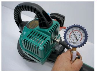
FIG. 2 A compression check is a simple test that measures the amount
of pressure produced in the combustion chamber in the compression stroke.
Often, complete diagnostics can't be con firmed until the engine machine is actually disassembled. For example, if a two-stroke engine develops a rattle in the top end, an experienced technician may recognize the sound and tentatively conclude that the piston is worn out. That would be the diagnosis. The technician wouldn't be able to confirm the diagnosis without disassembling the engine and actually seeing that the piston and cylinder are worn or damaged.
Correctly diagnosing problems is sometimes the most difficult and important part of a technician's job. Diagnosis is difficult because the technician often can't see the defective part before disassembly. Correct diagnosis is important because a technician must not waste time disassembling and inspecting parts that haven't failed.
Problems can also be detected by performing a compression check on the engine before it's disassembled (FIG. 2). A compression check is a simple test that measures the amount of pressure produced in the combustion chamber in the compression stroke. The compression is measured with a compression gauge that's inserted in the spark plug hole.
If the piston rings are worn, the compression gauge displays a pressure reading that is lower than the manufacturer's specification.
The reading is low because, instead of being compressed, some of the air-fuel mixture is leaking down past the worn rings and into the crankcase. The compression gauge may show an extremely high reading if there is excessive build-up in the combustion chamber area.
To perform a compression test, install the tester in the spark plug hole in the cylinder head, open the throttle wide open, and turn the engine over until the compression gauge no longer rises. It's important to note that the throttle has to be wide open to allow maximum flow of air into the engine.
Another important test that can be performed on a two-stroke engine is a crankcase pressure and vacuum test. Pressure testing is important to locate leaks at seals, gaskets, or cracks in the crankcase or cylinder. Vacuum testing identifies leaks at the seals. It should be noted that some manufacturers require that a vacuum and pres sure test be done prior to disassembly of the engine. A crankcase pressure test should be done before and after rebuilding an engine. A crank case pressure tester consists of a pressure pump, gauge, check valves, hoses, spark plug adapters, and rubber plugs. To perform a pressure test you'll need to plug off the intake and exhaust ports and install the spark plug adaptor. Attach the pump with a hose, pump between 6 and 9 pounds per square inch (psi) of pressure into the engine, and verify if it holds pressure. If it does not hold pressure, use a spray bottle with soapy water to search for leaks.
As this section covers the top end of the two stroke engine, we're going to discuss some engine problems and give the possible diagnoses. In diagnosing, you should have a mental picture of the parts connected with the problem. Table 1 lists some common problems you might encounter.
We'll get into troubleshooting in detail in Section 17, but as you'll see, you can handle quite a few common engine repairs by disassembling the top end of the two-stroke engine.
Repair Procedures
The procedures in this section are general in nature and their purpose is to familiarize you with the types of activities you'll encounter when working on the top end of a two-stroke engine. Always refer to the appropriate power equipment engine service manual for disassembly information.
The service manual contains all the information required to perform the job correctly, including detailed instructions regarding the specific model of power equipment engine, special tools, and ser vice tips. Above all, the service manual contains information on safety procedures.
DISASSEMBLY OF THE TWO STROKE ENGINE TOP END
The components of a typical two-stroke engine are illustrated in FIG. 3. This exploded view of a typical two-stroke engine is what you would see at the beginning of most manufacturer service and parts manuals. The top end assembly of a typical two-stroke engine consists of the following parts:
Cylinder and head assembly (26)
Cylinder base gasket (32)
Cylinder mounting bolts (25)
Piston and piston rings (23 and 24)
Piston wrist pin and retaining clips (31)
We had discussed in Section 7 the differences between an air-cooled and a liquid-cooled engine. You may wish to review these differences before working on a two-stroke engine. In this section, you'll find a discussion of an air-cooled, single cylinder two-stroke engine, as it's the most common design found in today's power equipment engines. Although they have differences in features, both air- and liquid-cooled two-stroke engines use similar approaches to disassembly and assembly procedures.

Table 1 Diagnosing engine problems
As there are many power equipment engine manufacturers building two-stroke engines, it would be impossible to show you how to disassemble the top end of every engine. So we'll discuss the basic procedures using a typical two-stroke engine as a guide. It's strongly recommended that you use the manufacturer's service manual and follow the procedures indicated therein when disassembling any engine. For the purpose of illustrating the diagnosis methods described in this section, we'll be using an air-cooled Weed Eater gas blower, which uses a Poulan power equipment engine (FIG. 1). Generally speaking, the procedures for the disassembly of most two-stroke engines are the same as required for this engine.
As you disassemble the top end, look closely at all the parts and record your observations.
Note any possible sources of damage to any of the parts. Note any marks on the piston and the rings. Your notes will be valuable as you complete your inspection of the individual parts.
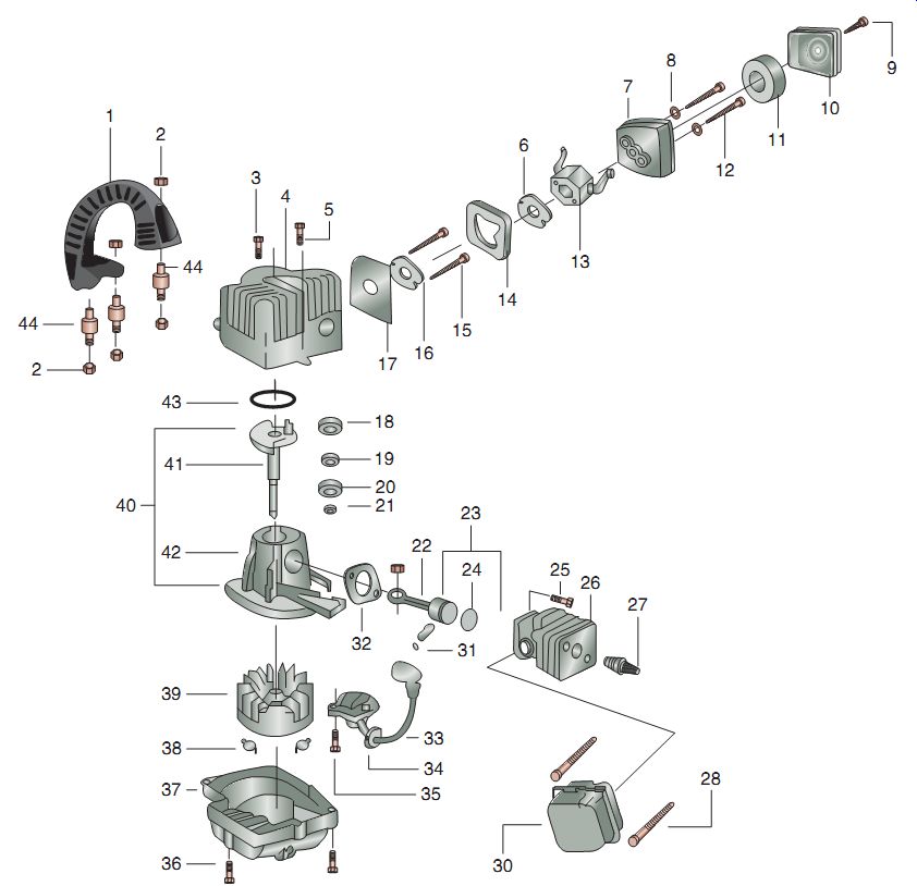
FIG. 3 The components of a typical two-stroke engine in exploded view
format.
CLEANING AND INSPECTION OF THE TWO-STROKE ENGINE TOP END
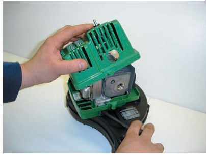
FIG. 4 Removing the engine cover exposes the external components to the
two-stroke engine's top end.
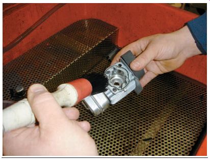
FIG. 5 Careful cleaning of all the components is an important part of
the disassembly process.
Removing the engine cover(s) will expose the external components to the two-stroke engine's top end (FIG. 4).
Repairs on the top end of a two-stroke power equipment engine generally don't require that the engine be removed from the implement. However, once removed, it's important to clean and inspect each component before reassembling. This inspection process, which will be described here, includes Inspecting and measuring the cylinder Checking for cylinder wear Inspecting and measuring the piston Fitting new piston rings to the cylinder Measuring top end components forms part of this inspection. The purpose of these measurements is to determine if a part is excessively worn. You should always measure the following top end components:
- Cylinder Piston
- Piston rings
Knowledge of certain measuring tools such as micrometers and bore gauges is essential to completing some of these inspections. You may refer to Section 3 for a discussion of the function of such tools.
The special measuring tools you'll use to complete the top inspection are
Dial bore gauge
Outside micrometer
Inside micrometer
Feeler gauge
Compression gauge
Cleaning Top End Components
Cleaning and visual inspection of all parts and top end components is important (FIG. 5).
In the process of carefully cleaning all the components included in the two-stroke engine top end, you'll prevent potential problems, before they can occur. You'll need degreasing solvents to remove carbon deposits and oil deposits on the piston. Brush gently and use special care not to damage any parts, as many may be fragile. You may need a wire brush and a scraper to remove residual gasket materials from gasket surfaces and excess carbon from the cylinder exhaust port and the cylinder head. Wash all parts in an approved solvent and dry with regulated, compressed air pressure and a lint-free shop rag. Remember that cylinders are made of aluminum, which is a relatively soft metal; so be careful you don't dig into them when cleaning with a scraper or brush. Remove any remaining old gasket material from the cylinder and crank case joint-mating surfaces. That's where the cylinder joins the crankcase. Warning: Never use gasoline or other highly flammable liquids to wash parts. Uncontrolled fires are easy to start, but hard to stop.
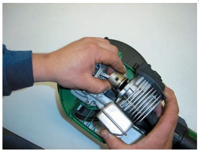
FIG. 6 The combination of a cylinder and the cylinder head in small two-stroke
power equipment engines is also called "jug."
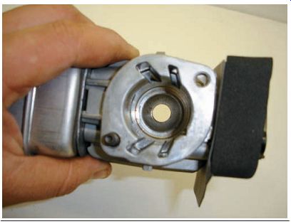
FIG. 7 Check for small cracks or other damage in the combustion chamber.
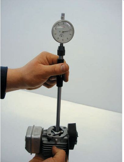
FIG. 8 The measuring of the bore of the cylinder with a dial bore gauge.
Cylinder and Cylinder Head Inspection
The cylinder and cylinder head in small two stroke power equipment engines are combined in virtually every case (FIG. 6). Another word for this combination often used is "jug." The head is the component that seals the upper end of the cylinder. Before inspection of the cylinder and head, be sure that it's clean.
Once the cylinder is thoroughly cleaned, you can check it for any visible signs of damage.
Check for small cracks or other damage in the combustion chamber area (FIG. 7). The most common problem in the cylinder head portion of the cylinder that you'll see is damage to the threads in the spark plug's hole from incorrectly installing the spark plug.
Cylinder Wall Inspection and Measurement
The first check on the cylinder comprises a visual inspection for cracks, scratches, and scoring marks. Once it has been verified that there is no visual damage or wear, measure the bore of the cylinder with a dial bore gauge to check for excessive wear (FIG. 8). Note that because of the ports used in the two-stroke engine, it's sometimes difficult to measure a point in the middle of the cylinder. Refer to the manufacturer's service manual to ensure that you measure all points of the cylinder as desired by the manufacturer.
This is to determine the extent of wear within the cylinder wall. Movement of the piston and rings within the cylinder causes cylinder wear.
The area of greatest wear is the area in which the rings travel. This is because the rings press tightly against the cylinder wall to seal the compression into the cylinder. In the area of ring travel, more heat is generated on the front and backside of the cylinder wall. By front and backside, we mean sides at a 90° angle to the wrist pin.
Insert the dial bore gauge into the cylinder at a point near the top of the ring travel. Take a gauge reading. Move the dial bore gauge to a point near the top of the exhaust port and take another reading, and then to the bottom of the exhaust port. Finally, move the dial bore gauge to a point near the bottom of the cylinder and take one more reading. Note that sometimes it will be difficult to find a good location toward the middle of the cylinder as the ports in two stroke engines make such a measurement difficult. Be sure to check the manufacturer's service manual to find the recommended locations at which cylinder bore measurements may be made.
Compare the readings; the difference indicates the amount of wear. Usually, the higher reading will be from the area of ring travel, that is, at the top. The difference is called cylinder taper.
The taper must not exceed factory specifications for the power equipment engine model you're repairing. Each model will have different specifications. If the "taper" exceeds allowable limits, the cylinder must be replaced or, if allowable, bored to a new size and fitted with a new, over sized piston and rings. Take the same readings at 90° for the first three readings to determine if the cylinder has become eccentric, that is, it's no more a circle (FIG. 9).
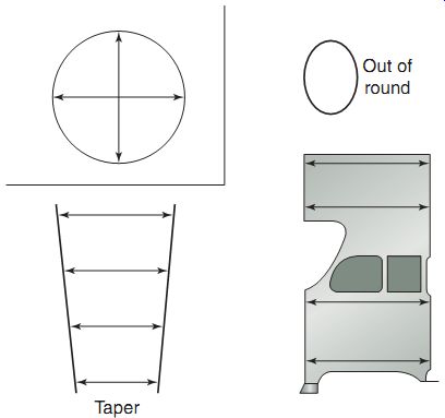
FIG. 9 A taper and out-of-round cylinder bore.
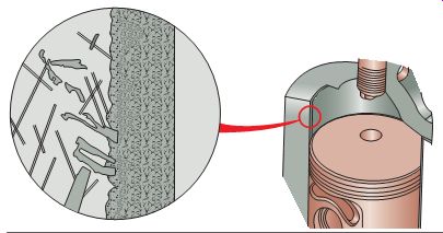
FIG. 10 Many two-stroke cylinders use a plated bore fused to the cylinder
wall and therefore can't be re-bored.
Boring Cylinders
Many two-stroke cylinders use a plated bore (FIG. 10) fused to the cylinder wall. This design greatly reduces weight and friction and improves heat transfer. However, in these cases, the cylinder can't be bored and must be replaced if its measurements are outside the manufacturer's specifications or if there is any damage to the cylinder.
Most of the typical power equipment two stroke engines can't be bored. Boring those cylinders that can be requires special machine tools and is therefore performed by a specialist.
Cylinder reboring can be done at some power equipment engine dealerships, but it's generally done at a machine shop that's set up to handle such a job. In many cases, it's more economical to replace the cylinder than to bore it.
If you have determined that you must rebore a cylinder, first obtain a correct oversized piston. Then, bore the cylinder to fit the piston in.
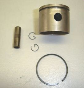
FIG. 11 The piston assembly consists of the piston wrist pin, clips,
and the piston ring.
Piston Assembly Inspection
As you'll recall, the piston is the cylinder shaped component that moves up and down the cylinder bore. The piston assembly consists of the piston itself, its wrist pin (or piston pin), clips to hold the wrist pin in place, and the piston ring(s) (FIG. 11). An engine produces its power by burning the air-fuel mixture in the combustion chamber directly above the piston.
Each time the spark plug fires, this air-fuel mix ture ignites with an explosive force. The burning process heats the gases, causing them to expand rapidly and forcing the piston down the bore.
This piston movement enables the engine to perform useful work. As you can imagine, the piston must withstand a lot of force as well as tremendous heat during an engine's operation. Therefore, as part of the rebuild procedure, you must inspect the entire piston assembly carefully for any damage. Note that the piston wrist pin retaining clips must always be replaced after they're removed. It's also recommended that the clips be reinstalled with their open ends facing up or down in relation to movement of the piston. Some theorize that if the clips are installed otherwise, they can compress and fall out under high engine speeds.
Visual Examination
Start the piston assembly inspection with a visual examination of the piston itself (FIG. 12). Check for cracks or any other signs of surface damage, such as scratches or score marks. Pay particular attention to the front and the backside of the piston. You should examine the piston in areas of both the skirt and the rings; these areas are the most common sites of damage. Look for signs of surface damage on the piston's skirt. One of the most common types of piston damage is scoring on the piston's skirt. Score marks are deep, vertical scratches on the skirt. A similar type of damage is scuffing. Scuff marks are wide areas of wear on the piston. Scuff marks usually appear as shiny patches. Scuffing may or may not be accompanied by score marks and is generally present on the bottom of the piston as it's installed in the cylinder.
A variety of conditions may cause both scoring and scuffing. In most cases, excessive friction and heat create the marks. Under certain conditions, the temperature in a cylinder can approach the melting point, or weld point, of aluminum. A problem in an engine's cooling system or excess friction between the cylinder wall and the piston rings can cause these high temperatures. Excessive friction is caused often by improper lubrication or from the piston fit ting too tightly within the bore. Minor scuffing can be removed using a fine emery cloth to clean the surface of the piston (FIG. 13).
If you find score marks or scuffing marks on a piston, try to determine the cause so that you can prevent the damage from recurring.
This is one of the occasions when you can take advantage of the notes and observations you had made earlier, in the disassembly process. During disassembly, you should have noted defects, if any, on gasket surfaces. If you did note a possible source of damage during disassembly and later found marks on the piston, you already have important clues for use in the troubleshooting process. In such a situation, you may also want to talk to the customer or operator to find out if the engine was overheating during operation.
Engine overheating, in addition to causing scuffing and scoring, usually produces a buildup of oil residue on the piston and the rings. Extreme heat breaks down the viscosity of oil and reduces its lubricating ability. Once oil breaks down, it begins to "bake" onto the engine components, forming a residue that resembles varnish. This residue can coat the piston rings and under extreme conditions can cause the rings to stick firmly to the piston. If this occurs, the rings will no longer be able to seal the combustion chamber properly. Therefore, always check to ensure that the rings are free to move on the piston and that both the piston and the rings are free of any buildup of residue.
Although the skirt is the most frequently damaged site on a piston, you must also care fully examine the piston's crown (FIG. 14). If you find any damage, try to determine the exact cause so that you can prevent that damage from recurring. Any damage to the crown is usually the result of the fuel mixture burning improperly in the cylinder. If the fuel mixture ignites incorrectly or at the wrong time, a violent explosion can result. The concentrated heat created in such an explosion can burn a hole through the piston's crown. Also, the explosion itself can be powerful enough to knock a hole right through the top of the piston. You may find small fragments lodged in the piston crown. This is an indication of lower end bearing failure, with the fragments being connecting rod bearing particles.
We'll discuss common problems that occur in an engine that cause piston damage in Section 17, which is on troubleshooting. As the final stage of your visual inspection of the piston, check the underside of the piston (FIG. 15).
It's in this area that the connecting rod is attached to the piston. Because the interior of the piston isn't directly exposed to the high heat of the combustion chamber and generally remains well lubricated, you'll usually find no signs of damage there. However, you should still check to make sure there are no cracks and that the wrist pin fits properly into the piston.
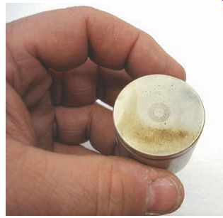
FIG. 14 An examination of the piston crown is mandatory to ensure no
damage has occurred.
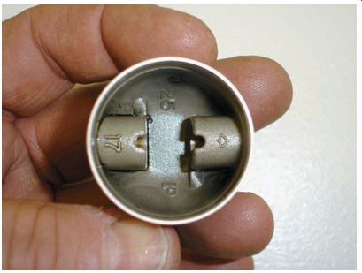
FIG. 15 Check the underside of the piston for cracks or other damage.
Piston Measurement
A typical piston appears to have a simple, cylindrical shape, much like a can. However, looks can deceive. Pistons are not perfectly round, and they don't usually have perfectly straight sides when at room temperature. In fact, a typical piston is manufactured with a taper, that is, the diameter at the very bottom of the piston's skirt is larger than the diameter at the piston's head.
Why does the piston have this taper? The reason is the variation of heat from one end of the piston to the other. Pistons, as we know, are made of aluminum, and aluminum expands as the temperature rises. A piston, however, gets hot at its head (where the combustion actually occurs) but remains relatively cool at the skirt (which is comparatively far away from the combustion chamber). Because the piston gets hotter at the top and also has more mass at the top than at the bottom, its top expands more than does its bottom.
To compensate for this difference in expansion, a piston is made with a built-in taper. As the piston gets hot, it expands and assumes a cylindrical shape. You should also note that almost all two stroke engine pistons have an arrow or marking that points toward the exhaust port to ensure that the piston is installed correctly.
A piston's shape is designed to compensate not only for the piston's expansion but also for the forces exerted on it. In the typical operation of an engine, the expanding gases force the piston both downward in the cylinder and against the cylinder walls. The piston's wrist pin links the piston to the connecting rod. Therefore, both the piston and the rod move together to rotate the crankshaft.
FIG. 16 shows the way the piston is connected to the crankshaft, causing a force to be directed toward one side of the piston on each upstroke and downstroke. This side of the piston is called the thrust face and is in a plane that's parallel to a line running through the length of the wrist pin. The forces applied during a power stroke are greater at the thrust face than they're elsewhere on the piston's sides. Therefore, a piston is usually made so that the diameter measured at a right angle to the wrist pin is slightly larger than the diameter measured along the wrist pin's length. This means that if you were to look at the head of a piston from above, the piston would appear to be slightly egg shaped. The wrist pin divides the egg shape into its wide and narrow halves. The piston's thrust face would be at the wide half.
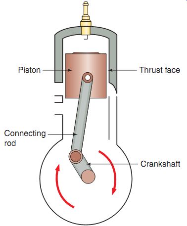
FIG. 16 Pistons have two thrust surfaces: the back side on the downstroke
and the front side on the upstroke.
As we've already discussed, the downward force applied to a piston on the engine's power stroke pushes the piston's thrust face against the cylinder wall. During the application of this force, the shape of a piston will become more round. Note that the egg shape of an actual piston is usually very slight and difficult to see with the eyes alone. However, if you measure the diameter at a right angle to the wrist pin and compare it with a diameter measured along the wrist pin's length, you should be able to note a difference between the two measurements.
Once the piston has been visually inspected, you can prepare the piston for measurement.
Before measuring the piston, remove the piston ring(s). To remove a piston ring, you must spread the ring open so that you can slide it out of its ring groove and off the piston. Most technicians spread piston rings open by hand (FIG. 17).
Measure and record the piston outside diameter at an angle of 90° to the wrist pin bore, as shown in FIG. 18. Note that the micro meter is placed at the bottom of the piston skirt.
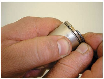
FIG. 17 When removing the piston ring, be careful not to spread the ring
too much or else damage may occur.
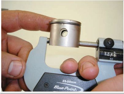
FIG. 18 Measuring the piston with a micrometer.
Some manufacturers will have a specific point at which to measure the piston. Be sure to check the appropriate service manual specifications and procedures when measuring a piston.
Once you've measured the piston's diameter, compare your measurement with the appropriate specification in the manufacturer's approved service manual. If the diameter of your piston is outside of specifications (generally, this measurement would be lesser than the specification), the piston should be replaced. If the piston is within specifications and shows no signs of damage, you can reinstall it in the engine.
Always remember to replace piston rings, even if you reuse the piston. The piston ring grooves, which are cut into the sides of the piston, hold the piston rings in place. The ring lands are the uncut areas between the ring grooves.
The ring grooves are actually slightly wider than the piston rings. As a result, the rings can move slightly, or float, within their grooves. Thus, the rings are able to actively conform to the cylinder walls while the engine is operating. The small space between each piston ring and the inner side of its groove is called piston ring side clearance.
The combustion gases forcing themselves onto the piston get into the ring grooves and leave behind a residue. Therefore, to inspect the ring grooves for excessive wear, you must first clean the grooves thoroughly. As the piston is made of aluminum, a soft metal, be careful not to dig into the piston while cleaning and inadvertently remove any metal, especially along the inner sides of the ring grooves. The best tool to use is an old piston ring. Made of a very tough material, old piston rings work well because they fit the ring grooves perfectly and therefore won't damage the sides of the grooves. If you want to use an old ring for this purpose, break it in half to produce a scraper-like edge. Then, insert the edge into the groove and scrape the residue out.
Once the ring grooves are cleaned, the piston can be wiped off and the side clearance for the piston rings can be checked. As mentioned before, this dimension is the clearance between the piston ring and the inner side of the ring groove. This small clearance performs an important function. During the power stroke, the pres sure produced by combustion pushes the piston down the cylinder bore. Some of the expanding gases also force down along the side of the piston and behind the floating piston ring.
The resulting pressure behind the piston ring forces the ring outward hard against the cylinder wall, thus helping to seal the combustion chamber better. By allowing the ring to seal better, the proper ring side clearance helps the engine produce more power.
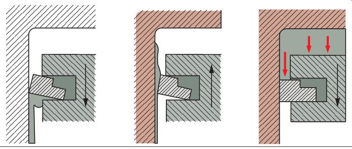
FIG. 19 Piston rings move around while the engine is running to scrape
off extra oil and aid in combustion.
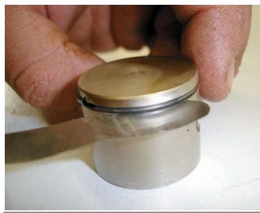
FIG. 20 Measuring ring side clearance.
Because a small clearance should always be present, a piston ring will tip slightly under normal operating circumstances, as illustrated in FIG. 19. As the piston goes down the cylinder during the intake stroke, the ring tips and scrapes excess oil off the cylinder wall. During the compression and exhaust strokes, the piston rises and the tipped ring glides over the oil film remaining on the cylinder wall. During the power stroke, the forces pushing down on the ring cause it to sit squarely, providing a better seal and therefore better power.
A proper ring groove clearance can be critical.
If the clearance is too large, the ring will tip excessively as the piston moves up and down, reducing its ability to seal. The excess movement of the ring on the piston may also cause the ring to break. If the clearance is too small, the ring may bind in its groove when the piston heats up and expands.
To measure the ring side clearance, a piston ring can be installed in its groove. A feeler gauge is then inserted between the ring and the bottom of the groove (FIG. 20). After you've measured the piston ring side clearance, compare your measurement with the manufacturer's specification. Because each ring groove may be worn differently, you should check the side clearance in all of the piston's grooves.
Piston Ring Inspection and Measurement
The next step in the inspection process is to carefully check the piston rings for signs of unusual wear. As mentioned earlier, you should not reinstall old piston rings into a cylinder; they should be replaced whenever an engine is taken apart. Generally, rings that are reused won't seat properly, resulting in poor engine performance. However, the condition of old piston rings can provide clues to certain engine problems. For example, small scratches found on the edge of the rings usually mean that dirt or other debris has been getting into the engine.
This may likely indicate a faulty air-filtering system. Remember from Section 6 that two stroke pistons have locating pins to prevent the piston ring from moving around on the piston (FIG. 21).
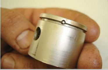
FIG. 21 Locating pins prevent the piston ring from moving into a port
and causing damage in a two-stroke engine.
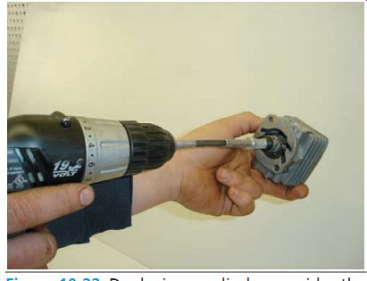
FIG. 22 Deglazing a cylinder provides the best seal and quick break-in
when replacing a piston and/or piston ring.
You may recall that when new piston rings are installed in an engine, they must wear them selves into position against the cylinder walls to form a tight seal. Once this process of seating has occurred, the rings lose the ability to do so again, that is, if old rings are reinstalled in an engine, they won't be able to conform once again to the cylinder walls and make a tight seal.
Without a tight seal, the combustion gases can leak past the rings. This reduces the amount of horsepower the engine can produce.
Before reassembly, you'll be required to deglaze the cylinder (FIG. 22). The importance of cylinder wall deglazing can't be overemphasized. A proper cylinder finish will provide the quickest possible break-in and greatly reduce the possibilities of ring or piston scuffing during break-in. A glazed cylinder wall causes rings to "skate" on the highly polished finish and discourages the minute amount of wear that's necessary to mate the piston rings with the bore of the cylinder.
A deglazed finish contains minute hills and valleys, which carry a film of oil, which will prevent scuffing during break-in as well as pro duce the type of cylinder finish piston rings can mate to rapidly. The finish produces a cross hatch pattern that intersects at approximately a 45° angle. Probably the most critical part of the deglazing operation is proper cleaning after deglazing. The residue of deglazing-tiny pieces of iron from the cylinder wall-will rap idly destroy all moving parts if left in the engine.
It's important to note that cylinders need to be cleaned thoroughly with warm soap and water prior to assembly. Clean until the bore can be wiped with a clean white cloth without soiling the cloth. Many technicians finish the cleaning process by wiping the bore with automatic transmission fluid because of its ability to pick up tiny pieces of metal. After clean up, oil the area lightly with the same oil that will be used to run the engine, to prevent rust formation (FIG. 23).
FIG. 23 It's important that cylinders be cleaned thoroughly before assembly.
FIG. 24 Measuring piston ring end gap with a feeler gauge.
Measure the new piston ring(s) to ensure that the ring end gap is correct by placing the ring squarely into the cylinder (use the piston to do this effectively) and measuring the piston ring end gap with a feeler gauge (FIG. 24). Piston ring end gap is the space at the ring at its opening when it's compressed in the cylinder.
When checking ring end gap, locate the ring in the top of the cylinder and measure at a point that the engine manufacturer recommends in the appropriate service manual.
Measuring Piston-to-Cylinder Clearance
As explained earlier, a piston expands as its temperature rises. Since the metal of the piston typically expands more than the metal of the cylinder wall, some clearance must be allowed between these components when both are cold.
This clearance is called the piston-to-cylinder clearance (or just piston clearance for short). The piston-to-cylinder clearance is a critical dimension. If the clearance is too small, the piston fits too tightly in the cylinder whenever the engine heats up, resulting in excessive friction, which may cause the piston to seize in the bore, that is, the piston may actually melt onto the cylinder, thereby being unable to move up and down. Try rubbing your hands together lightly. There is little heat produced because there is very little friction.
Now try rubbing together with much more force against each other and quickly. You'll almost immediately feel the heat being produced from the friction created. If this occurs, the engine stops running, and the starter won't be able to rotate the crankshaft at all. You may be able to free a seized piston after the engine cools down again; however, both the piston and the cylinder wall will probably be badly scored and damaged.
If the piston clearance is too large, the piston won't be held in place well and will tend to rock back and forth while the engine is running. This rocking motion creates a knocking noise and may eventually break the piston skirt. In addition, the piston ring's ability to seal the combustion chamber will be greatly reduced. You should always check the manufacturer's specification for the correct piston-to-cylinder measurement listed in the service manual, since all engines are designed slightly differently.
To determine the piston clearance in an engine, you'll need to measure the diameter of both the piston and the cylinder bore. Illustrations of these measurements can be seen in Figures 10-8 and 10-18. Compare your measurements with the manufacturer's specifications. Then, subtract the outside diameter of the piston from the inside diameter of the cylinder bore. The result of your calculation is the actual piston clearance. Compare your calculated clearance with the manufacturer's specification. If the clearance is outside specifications, the piston and cylinder will have to be replaced or resized to make the clearance conform to specifications.
Wrist Pin Measurement
The wrist pin, a cylinder-shaped piston assembly component, is used to link the connecting rod to the piston. The connecting rod's bearing surface for the wrist pin allows the end of the rod to rotate freely around the wrist pin as the piston travels up and down. The wrist pin must transfer each power stroke's down ward physical force from the piston to the connecting rod. To ensure the wrist pin is strong enough to handle this task, the engine manufacturer usually makes the pin from high quality steel, which is a very hard metal. For this reason, you won't usually see any wear on the pin itself. However, to guarantee that a wrist pin isn't worn, measure the pin's diameter with an outside micrometer (FIG. 25). Compare your measurement with the specification given in the service manual.
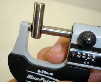
FIG. 25 Measuring the wrist pin.
FIG. 26 The two-stroke engine rod will usually use a bushing or needle
bearing at the small end.
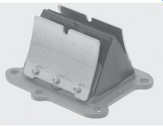
FIG. 27 Some power equipment two stroke engines use a reed-valve-type
induction system.
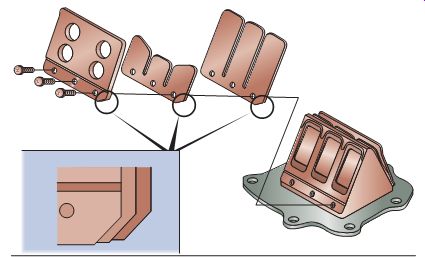
FIG. 28 The parts of the reed-valve assembly that require inspection.
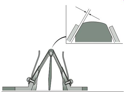
FIG. 29 There should be little to no air gap between the reed valve and
the reed valve seat.
Connecting Rod Inspection
The connecting rod in a two-stroke engine is generally a one-piece unit and is attached to the crankshaft. The two-stroke engine rod will usually use a bushing or needle bearing at the small end (FIG. 26) and a needle or roller bearing at the large end, depending on the size of the engine.
Reed Valve Inspection
Many two-stroke power equipment engines use reed valves on the intake side of the induction system (FIG. 27). Checking the reed valves is a simple process of inspecting the reed's valves, reed stopper, and the reed valve seat (FIG. 28) for physical damage.
When looking at the reed valve assembly, there should be little to no air gap between the reed valve and the reed valve seat (FIG. 29).
STARTING THE REASSEMBLED REBUILT ENGINE
When you're certain that all components have been reassembled and are in place, all fasteners have been properly tightened, and the fluids have been properly added, it's time to start the engine. The engine should start within 5-10 pulls of the starter rope. If it doesn't start at this time, stop and verify that all electrical connectors are attached and then try again. Once started, let the engine idle or keep it as close to idle speed as possible. As the engine is warming up, check for any leaking fluids in and around the engine. Shut the engine off.
Engine Break-In
Most manufacturers recommend that a new (or reconditioned) engine be properly broken in to make sure that all components are sealing well and that all components mesh together properly. During your assembly, use only the best possible materials and use original equipment manufactured parts to assure the highest standards. Even though you're using the highest quality components, it's still necessary to allow the parts to "break in" before subjecting the engine to maximum stress. The future reliability as well as the performance of the two-stroke engine depends on a proper break-in procedure.
This includes extra care and restraint during the early life of the reconditioned engine. Follow the appropriate manufacturer recommendations for the correct break-in procedure.
Summary
Diagnosis is the process of determining what's wrong when something isn't working properly, by checking the symptoms.
Symptoms are the outward, or visible, signs of a malfunction.
It's important to understand fully the necessity for proper engine component inspection, which includes visual inspections as well as measurement of components for wear.
QUIZ
1. To measure the diameter of a piston, you should use a .
2. A piston ring groove clearance can be measured by using a .
3. An engine produces its power by burning the air-fuel mixture in the combustion chamber directly above the .
4. If the piston clearance is too small, the friction between the piston and the cylinder may cause the piston to in the bore.
5. A between the cylinder and the crankcase helps create an air-tight seal.
6. Wear within the cylinder is caused by the up-and-down motion of the and .
7. An indication of worn piston rings can be seen before the engine is disassembled by conducting a test.
8. All two-stroke cylinders can be bored to fit an oversized piston. (True/False)
9. To measure the cylinder bore, you would use a ___.
10. Pistons are perfectly round to fit in the cylinder. (True/False)