AMAZON multi-meters discounts AMAZON oscilloscope discounts
Goals:
- Define fuel octane rating and state the factors that affect fuel octane ratings
- Explain the primary principles of carburetor operation
- Identify various fuel delivery systems used in power equipment engines
- Identify the components of each type of carburetor
- Describe the operation of circuits in each type of carburetor
- Understand the purpose of fuel injection
- Identify the components of an electronic fuel injection system
INTRODUCTION
All engines require fuel and a way to mix the fuel with air to operate. For power equipment engine repair, it's important to have a good understanding of both engine requirements. In this section, you'll first learn about the fuels used for power equipment engines. You'll then learn about the principles of carburetion. We'll discuss the types of fuel delivery systems used to get the fuel from the fuel tank into the engine.
Finally, we'll discuss the different types of carburetors found in power equipment engines and will cover basic fuel injection systems.
FUEL
When we speak of fuel in relation to the gasoline-powered internal combustion engine, we're referring to gasoline. Gasoline (or a gasoline-and-oil mixture) is the fuel used in most standard power equipment engines.
Gasoline is a volatile (vaporizes easily), flammable (burns easily), hydrocarbon (chemical compound of carbon and hydrogen) liquid mix ture used as a fuel. Oxygen must be present for gasoline to combust (burn).
Gasoline is obtained from crude oil by a process called fractional distillation, which is based on the fact that each hydrocarbon boils or vaporizes within a certain temperature range.
Thus, crude oil is heated in stages until all the various hydrocarbon classes have been individually vaporized and collected. Additives are then blended with the gasoline to give it required properties.
The primary requirement of a fuel is that it gives satisfactory engine performance over a wide range of conditions. Fuel is rated by a method known as fuel octane rating or knock rating. Octane rating is a measure of a fuel's ability to resist detonation. The higher the octane rating, the higher the fuel's resistance to detonation. Detonation, also known as engine knocking, is the explosion of highly compressed air and the unburned fuel mixture in the cylinder. Excessive detonation can cause catastrophic damage to the inside of the engine, by breaking a piston or cracking a cylinder head. Today, isooctane and heptanes are the main additives used in gasoline to help it resist detonation.
There's no advantage to using gasoline of a higher rating than what the engine needs to operate detonation free. There are several factors that influence the octane rating needs of a power equipment engine. On the same line, it's important to use the recommended octane rating given by the manufacturer to prevent dam age to the engine. Listed in following text are factors that influence detonation.
Higher engine and air temperatures encourage detonation.
Higher altitudes discourage detonation. An air-fuel mixture that is too lean (a mixture in which the mass of air is more than 14.7 times the mass of fuel) encourages detonation.
How the engine is run also affects chances of detonation. The heavier the load the user applies to the engine, the greater the chance that detonation will occur.
As you can see, different factors can influence the octane rating needs of a power equipment engine. The most important thing to remember is to use a gasoline with an octane rating that meets the power equipment engine manufacturer's minimum requirements. This information is pro vided by every engine manufacturer and can be found in the owner's manual of the machine.
Discussed in following text are two fuel mixtures commonly used.
Oxygenated fuels have an oxygen-based component such as alcohol or ether that contains more oxygen than is normal. Adding oxygen to fuel helps the fuel to reduce harmful carbon monoxide emissions from the engine.
Ethanol alcohol (also known as gasohol) is an engine fuel made by blending gasoline with alcohol distilled from farm grains like corn.
Alcohol is a clean burning fuel, and up to 10% can be blended with gasoline. Such a mixture burns with combustion results similar to those of straight gasoline. Alcohol, however, can damage rubber, plastic, and brass used in fuel systems, and some kinds of alcohol can damage the metals used in the casting of carburetors.
Also, water is easily absorbed by alcohol. There fore, it's important to make sure if the engine manufacturer has approved the use of any blended alcohol in engines, as it's used in abundance in some parts of the country. Generally, state law requires that consumers at the pump be informed when the fuel supplied carries gasoline blended with alcohol.
OXYGEN
Oxygen is a tasteless, odorless, colorless gas that's present in the very air we breathe, which holds about 21% oxygen. It's drawn into the engine and combines with gasoline to form a combustible vapor. Pure oxygen has the ability to explode if submitted to extreme compression, and ignited oxygen produces a very high temperature and a great amount of energy. How ever, internal combustion engines don't receive pure oxygen and the compression ratio used is too low to cause the oxygen present to ignite on its own. Instead, a fuel mixture is combined with the intake air. The air-fuel mixture permits combustion to take place at a compression ratio lower than that required for pure oxygen to burn.
Therefore, a combination of air (oxygen) and fuel (gasoline) is necessary to obtain the explosion characteristics required to operate an internal combustion engine safely and efficiently.
THE CARBURETOR
The amount of power produced by an engine is directly related to the heat energy put forth by the air-fuel mixture. The more combustible the mixture becomes, the greater the amount of heat that's generated. Power equipment engines, as we know, have the ability to transform heat energy into usable power. The greater the amount of productive heat produced by combustion, the more power you can expect from the engine.
The carburetor is a device used to mix proper amounts of air and fuel together in such a way that the greatest amount of heat energy is obtained when the mixture is compressed and ignited in the combustion chamber of the engine.
The function of the carburetor is to mix the correct amount of fuel with sufficient air so the fuel atomizes (breaks up), allowing it to become a highly volatile vapor. When this vapor enters the combustion chamber of the engine and is compressed by the action of the piston, a spark ignites it, enabling combustion and creating the power to operate the engine. Maximum power from the fuel supplied will be obtained only if exact proportions of air and gas reach the combustion chamber of the engine in vapor form of precisely the right consistency.
When the fuel and air are combined within the engine's combustion chamber, a chemical balance is created, known to be the stoichiometric ratio. A stoichiometric mixture is the working point that modern engine designers attempt to achieve in their design of fuel induction systems. The term stoichiometric ratio describes the chemically correct air-fuel ratio necessary to achieve complete combustion of fuel. The ratio of air to fuel in a theoretically perfect stoichiometric mixture is 14.7:1; that is, the mass of air is 14.7 times the mass of the fuel. This means that, in a perfect situation, there would be 14.7 parts of air for each part of fuel. Any mixture in which the ratio is less than 14.7:1 is considered to be a rich mixture; any mixture in which the ratio is more than 14.7:1 is considered to be a lean mixture. It's important to note that this ratio is measured by mass and not by volume.
Table 1 lists the proper amounts of air and fuel, with regard to different engine running conditions.
You learned earlier that liquids don't burn. Gasoline is a liquid. Oxygen, on the other hand, is a gas and has the ability to burn. The most efficient combustion of gasoline and oxygen occurs only when they're combined and turned into a vapor from the heat produced by the engine.
This is a delicately balanced mixing process accomplished by the carburetor. Two primary principles are involved in carburetion operation:
- The principle of atomization
- The Venturi principle
Let's look at each of these principles in detail.
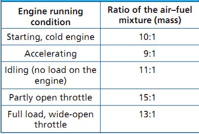
Table 1 Air-fuel mixtures at different engine running conditions
Principle of Atomization
Atomization is the process of combining air and liquid, in this case fuel, to create a mixture of liquid droplets suspended in air.
As the piston begins the intake stroke, the air pressure in the cylinder is reduced. The pressure difference causes the higher-pressure, outside air to flow through the air filter and carburetor, and into the engine. Atomization takes place when the carburetor meters gasoline into the fast moving air passing through it using the same principle of pressure difference (FIG. 1). Air at high pressure from the outside becomes air at low pressure in the carburetor, which allows the high-pressure air at the fuel source to be pushed into the throat of the carburetor. The primary function of the carburetor is to atomize the fuel to create an air-fuel mixture.
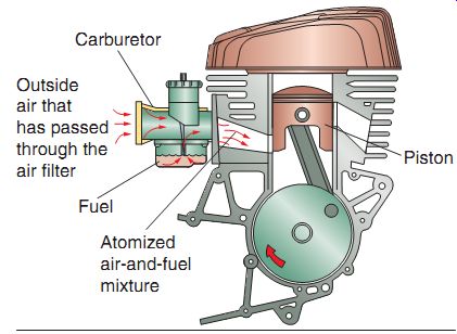
FIG. 1 Atomization is the process of combining air and liquid to create
a mixture of liquid droplets suspended in air. This illustration shows how
atomization takes place in an engine.
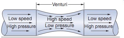
FIG. 2 The Venturi principle.
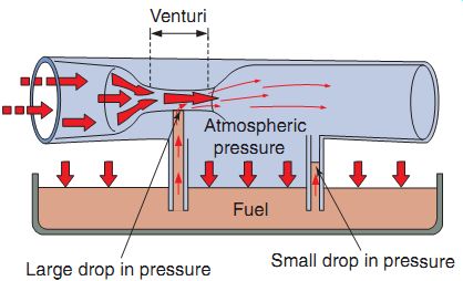
FIG. 3 The effect of low pressure in a venturi.
FIG. 4 A typical fuel tank. Note that the fuel tank is placed higher than
the carburetor and therefore uses a gravity feed system.
The Venturi Principle
Carburetor design is based on the Venturi principle. The Venturi principle simply states that a gas or liquid that's flowing through a narrowed-down section (venturi) of a passage will increase in speed and decrease in pressure compared with the speed and pressure in wider sections of the passageway (FIG. 2).
A venturi has a particular shape-a modified hourglass figure, you might say. Air from the carburetor, on its way to the combustion chamber, passes through the venturi. The hourglass shape of the venturi causes the stream of air to increase in speed and decrease in pressure, creating a pressure difference in the venturi. This pres sure difference is important, as it allows for fuel to be drawn into the air stream and atomized.
The major air passage in the carburetor body is called the carburetor bore. The air entering the carburetor bore is controlled by its speed and by the size of the venturi. A typical main carburetor bore may have a diameter of 1 inch, com pared with a venturi diameter of ¾ inch. When air rushes to fill the cylinder, the speed of the air is faster if it must pass through a small opening than if it must pass through a large opening. As mentioned earlier, as air speed increases, air pressure decreases. The speed of air as it passes through the carburetor is an important factor in the breaking up (or atomization) of the fuel, as well as controlling the amount of fuel that's delivered into the venturi. You can see from FIG. 3 that air is drawn into the carburetor through the venturi, where it gains considerable speed. This increase in air speed is directly related to a fall in air pressure in the venturi, which then draws fuel from an outlet nozzle. The fuel is atomized under the influence of atmospheric pressure as it's mixed with the incoming air.
Venturi size and shape are of considerable importance. If the venturi is too large, the flow of air is slow and won't atomize sufficient fuel to make a balanced mixture. If the venturi is too small, not enough air passes through to fill the vacuum created by the engine inside the cylinder. A large engine that creates a high vacuum uses a carburetor with a large venturi. A small engine requires a smaller venturi to be most effective.
Carburetors are equipped with mechanisms for regulation of the air and fuel volumes that are allowed to pass through the venturi. All carburetors have a venturi that operates on the same basic principle. Variations are in size, method of attachment, or in the system used to open and close the venturi. The principle of operation is the same for all carburetors.
FUEL DELIVERY SYSTEMS
The various components of the fuel delivery system of most gasoline-powered engines will be discussed in this section. Servicing fuel delivery systems is important and involves inspecting, cleaning, and replacing many of these components.
Fuel Tank
The fuel tank is designed to store fuel (gasoline). Fuel tanks can be made of steel, aluminum, or plastic. Fuel tanks of almost all modern power equipment engines are made of a light, thin steel or plastic. The important thing to remember is that the fuel tank is a reservoir that safely stores a supply of fuel for the carburetion system (FIG. 4). In many cases, the fuel tank uses a gravity feed system to allow fuel to flow into the carburetor. The fuel tank will always be placed higher than the carburetor when using the gravity feed system.
Typically, the fuel tank is vented to the atmosphere, but some states (California, for example) require fuel tanks to be vented into a charcoal canister. This canister retains the hydrocarbon vapors, keeping them from entering the air we breathe.
Fuel Valves
Fuel valves, also known as fuel petcocks, are on/off valves that control the flow of gasoline from the fuel tank to the carburetion system (FIG. 5). Fuel valves are generally operated manually by turning the valve either on or off.
When turned to the "on" position, fuel flows to the carburetor from the main fuel tank. When turned to the "off" position, the flow of fuel stops. These valves are useful when the engine is being transported or if the engine isn't going to be used for a long period of time.
Fuel Lines
Fuel lines are used to flow gasoline from the fuel valve to the carburetion system and are usually made of metal or neoprene, which is a synthetic rubber material. It's important to use manufacturer-recommended fuel lines. Because of some additives and alcohol (in certain cases where it's used as an additive) in gasoline manufactured nowadays, inferior fuel line hose can be affected or damaged.
Fuel Pumps
Some power equipment engines use a fuel pump. The purpose of a fuel pump is to deliver fuel from the fuel tank to the carburetion system. A fuel pump is also required when the power equipment engine's fuel tank is placed lower than the carburetor. The fuel pump sup plies fuel under pressure to keep the carburetor filled with fuel. Fuel pumps are found always in engines with fuel injection systems. Fuel injection is a type of carburetion and is discussed later in this section.
There are three types of fuel pumps- mechanical, vacuum, and electric. Although some larger power equipment diesel engines use mechanical fuel pumps, two types of pumps are commonly seen on modern power equipment engines: vacuum and electric.
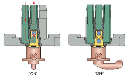
FIG. 5 Fuel valves are designed to open and close the flow of fuel to
the carburetor.
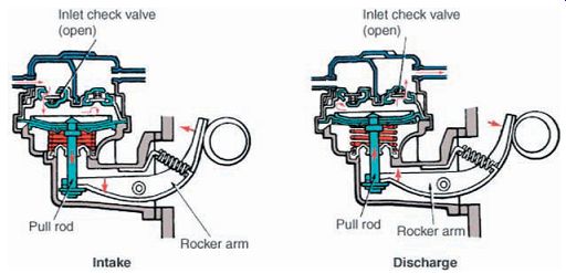
FIG. 6 A mechanical fuel pump.
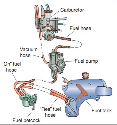
FIG. 7 A vacuum-operated fuel valve uses engine vacuum to allow fuel to
flow by use of a diaphragm, as shown here.
Mechanical Fuel Pumps
The mechanical fuel pump is a pump that uses a diaphragm operated by a rocker arm.
The rocker arm is opened by the camshaft and closed by a spring to pump fuel from the tank to the carburetor (FIG. 6). Mechanical pumps are generally located on the side of the engine block. The rocker arm enters the engine and rides on a camshaft lobe. As the cam rotates, the rocker arm moves up and down. The lever is connected to a diaphragm. A diaphragm is a flexible pumping element in the pumping chamber that, when moved, changes the volume of the chamber. There is an inlet and an outlet check valve located in the pumping chamber.
Pumping occurs when the diaphragm is moved up and down by the rocker arm. When the diaphragm is pulled down, the pressure difference pulls in fuel from the tank, and when the diaphragm is pushed back up, the check valve in the inlet side closes and the fuel is delivered to the carburetor.
Vacuum Fuel Pumps
The vacuum fuel pump (FIG. 7), also called an impulse fuel pump, uses a diaphragm that's moved by the pressure differences of engine vacuum and atmospheric pressure. It works in the same manner as the mechanical fuel pump but instead of a mechanical lever, the diaphragm is moved by pressure and vacuum made by the engine.
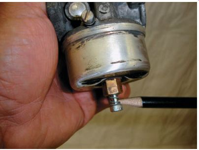
FIG. 9 A high-speed mixture screw.
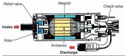
FIG. 8 A typical electric fuel pump.
Electric Fuel Pumps
The electric fuel pump is operated electronically by the use of an electric motor and sole noid that pumps the fuel from the fuel tank to the carburetor (FIG. 8). An electric fuel pump operates only when the power equipment engine is running, unless it's bypassed.
Vent Hoses
Vent hoses are used on most fuel tanks and carburetors to permit atmospheric air pressure to enter into certain important areas within the fuel system. If these hoses become plugged, twisted, or curled, the fuel will not flow correctly. Engines that can be used in multiple positions, such as handheld-based engines, don't use vent hoses; instead, they rely on a pressurized fuel tank to ensure delivery of fuel.
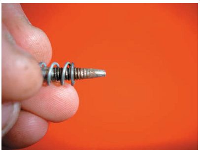
FIG. 10 The high-speed mixture screw has a taper in it to adjust the flow
of fuel in through the carburetor.
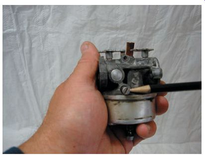
FIG. 11 A low-speed adjustment screw is typically on the side of the carburetor,
as seen here.
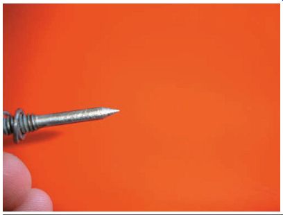
FIG. 12 The tip of the low-speed mixture screw is pointed, to allow for
a more precise adjustment.
Fuel Filters
Fuel filters help remove contaminants from the fuel before they reach the carburetor. Common locations are on the top of the fuel valve or petcock in the fuel tank, in the fuel valve, in line with the fuel hose, or in the carburetor.
Adjustment Screws
The engine needs a large volume of air and fuel when it runs at high speed. Fuel for high speed operation comes from the venturi pickup tube. The amount of fuel that goes up the pickup tube can be regulated and adjusted with a screw or a fixed jet. A high-speed adjustment screw (FIG. 9) is a carburetor screw used to regulate the amount of fuel that goes up the main pickup tube during high-speed operation. The screw has a tapered end (FIG. 10) that fits in the bottom of the carburetor float bowl and into the pickup tube. The screw is used to increase or decrease the size of the passageway for fuel to move up the pickup tube. If the screw is turned in, a smaller amount of fuel can go up the tube. If the screw is turned out, more fuel is allowed into the carburetor. A spring is used on the adjustment screw to prevent it from vibrating loose.
The throttle valve is in a nearly closed position when the engine is running slowly or at idle speed. A closed throttle valve allows very little air to flow through the venturi. During this phase of operation, very little or no fuel is pulled up the pickup tube. Fuel must be allowed into the engine so that it will run. This is done with a slow-speed circuit behind the throttle valve.
During idle, low pressure created at the throttle plate draws fuel through a passage and into the carburetor bore. The amount of fuel that comes out the hole can be controlled and regulated by a mixture screw (FIG. 11) or a fixed jet.
The low-speed fuel mixture screw is a carburetor screw used to regulate the amount of fuel that gets behind the closed throttle plate during low-speed or idle operation. The low-speed fuel mixture screw has a pointed end (FIG. 12) that goes through the side of the carburetor and into a low-speed fuel passage. If the screw is turned all the way in, very little mixture can pass through the circuit. If the screw is turned out, more fuel can pass through the circuit.
The low-speed fuel mixture screw should not be confused with the engine's idle screw, which is used to control the opening of the throttle valve. Always inspect the fuel adjustment screw tips to ensure that they're not damaged or bent.
Damage can occur by overtightening the screw when cleaning or adjusting.
Air Filters
Air filters are designed to filter the incoming air to the carburetor. Air filters are important to the life of an engine. If dirt or other contaminants are allowed to go through the carburetor with the air-fuel mixture, they'll damage the engine quickly. The two most popular materials used for air filters are paper and foam.
Paper Air Filters
The paper air filter (FIG. 13) consists of laminated paper fibers that are sealed at the ends or sides of the filter. Some paper air filters include a supportive inner or outer shell of metal screen. The paper used in these air filters is molded in an accordion-style pattern. This design increases the surface area and decreases the restriction to air passing through it. The paper air filter design must be kept dry and free of oil. If it becomes excessively dirty or has oil in it, the paper air filter must be replaced. Don't try to clean a paper air filter with soap and water. This will damage the paper fibers, rendering them unusable.
Foam Air Filters
Foam air filters (FIG. 14) use a special foam and oil to aid in trapping dirt and other contaminants. The foam air filter usually fits over a metal apparatus to help hold its shape.
These filters work by slowing down the incoming air and collecting particles of dirt as the air passes through the filtering material. The dirt sticks to the filter and remains there until the filter is serviced. When the filter becomes dirty, it can be cleaned in a warm, soapy water solution and then rinsed and dried. After drying, it must be oiled (FIG. 15). Some foam air filters are used in conjunction with paper air filters as a pre-filtering device (FIG. 16). In this case, it's sometimes recommended that a pre-filter not be oiled, to prevent saturation of the paper filter.
Oil Bath Air Filters
The oil bath air cleaner is a common type of air filter used in older engines. An oil bath air filter directs incoming engine air over an oil sump that catches dirt particles (FIG. 17). Like other air filters, the oil bath type is mounted to the carburetor. All the air going into the carburetor must go through the filter first. The housing is the main part of the oil bath air filter. The housing has air passages that direct the incoming air. Incoming dirty air comes in the top of the housing. It's then directed down the inside of the housing. The housing passages cause the air to change direction and start back up the housing.
There is a small oil sump in the bottom of the housing. The air entering the housing is made to change direction over the oil. Dirt in the air is too heavy to make the quick turn so it keeps going straight into the oil. The oil traps the dirt and the filtered air goes through an oiled screen.
Any dirt left in the air sticks to the oiled screen.
Filtered air then goes down the center of the housing and into the carburetor.
Oil bath air filters are not used in newer engines. The oil in the housing requires frequent service. The complicated air routing inside the housing limits the air flow into the engine, which limits engine power.
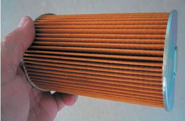
FIG. 13 The paper air filter is molded in an accordion-style pattern to
provide greater surface area.
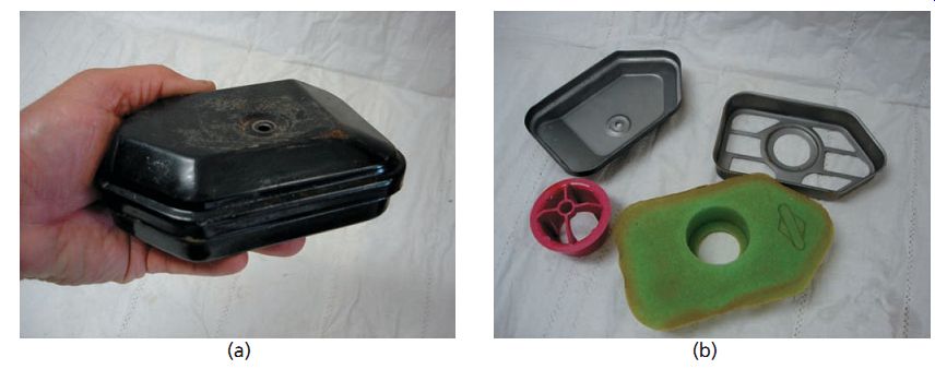
FIG. 14 A typical foam type air filter. (a) The assembled filter, (b)
the individual components of the filter, (c) the top of the filter, (d) the
bottom of the filter, which is where the air comes through, and (e) the filtering
process.
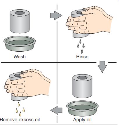
FIG. 15 When cleaning a foam air filter, wash it with soap and water,
rinse well and dry, apply proper oil as stated by the filter manufacturer,
and finish by removing the excess oil.
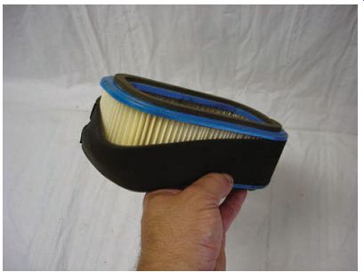
FIG. 16 Many power equipment engines use a combination of a foam and paper
air filter.
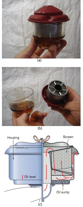
FIG. 17 While rarely seen now, the oil bath air filter was used on most
engines up until the 1960s. Kohler Co.
CARBURETOR TYPES AND OPERATION
Now we'll learn what makes up a carburetor as well as what happens inside during its various phases of operation. But first, recall that all carburetors work using the same basic principle. The carburetor has the task of combining the air and fuel into a mixture that produces power for the engine. First, the engine draws in air. The pressure difference between the outside atmosphere (higher pressure) and the inside of the cylinder (lower pressure) forces the air to pass through the carburetor. The air mixes with a predetermined amount of fuel, which is also moved by pressure differences, into the air stream of the carburetor venturi. Carburetors use different fuel metering systems, which sup ply fuel for the air-fuel mixture in regulated amounts. These metering systems are called fuel circuits, and their operating ranges overlap.
We'll discuss these circuits as well as the operation of the common carburetors that you'll see in power equipment engines. Let's begin by discussing starting a cold engine.
Cold Start Systems
For the cold start phase of engine operation, a rich fuel mixture is needed because the engine metal is cold. When the engine is cold, the air-fuel mixture is also cold and won't vaporize or com bust readily. To compensate for this reluctance to burn, the amount of fuel in proportion to the amount of air must be increased. This is accomplished by the use of a cold start system. Cold start systems are designed to provide and control a richer-than-normal air-fuel mixture, which is necessary to quickly start a cold power equipment engine. Most carburetor cold-start mixtures are designed to operate at a ratio of approximately 10:1, that is, 10 parts of air to 1 part of fuel. Carburetors manufactured today usually include one of three types of cold start devices.
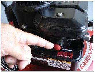
FIG. 18 A primer cold start system pushes fuel directly into the engine.
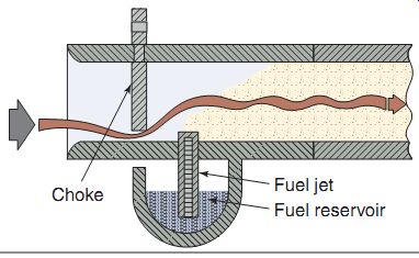
FIG. 19 The choke plate cold start system closes off air to the engine.
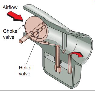
FIG. 20 The choke plate cold start system allows a predetermined amount
of air to flow into the intake tract.
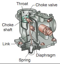
FIG. 21 A diaphragm type automatic choke and its related components.
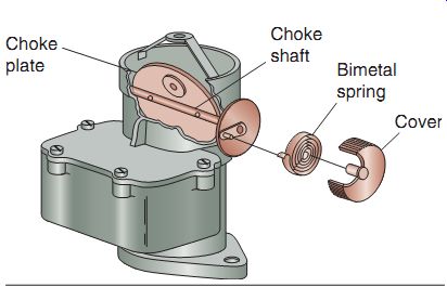
FIG. 22 A bimetal type automatic choke and its related components.
Primer Cold Start System
A primer cold start system is a rubber squeeze bulb used to force fuel into the combustion chamber past the carburetor to help start a cold engine (FIG. 18). There are two different types of the primer cold start system in power equipment engines: wet bulb and dry bulb. They can be mounted to the side of the carburetor or as a separate assembly mounted elsewhere in the engine. To start a cold engine with a wet bulb primer, the operator squeezes the bulb, which forces fuel out of the bulb-holding chamber past a check valve through the carburetor and into the engine. When the bulb is released, fuel is refilled back into the bulb from the fuel source. There are two check valves on a wet bulb primer: one to prevent fuel from entering the engine under low pressure (when the bulb is released) and one to prevent fuel from entering into the source under high pressure (when the bulb is being pushed). When used, the engine receives raw fuel in the intake port for an easier cold engine start.
The dry bulb primer pushes air into the carburetor bowl, which increases pressure in the bowl. The increase in pressure forces fuel through the carburetor and into the engine.
Choke Plate Cold Start System
The choke plate cold start system is an air restriction system that controls the amount of air available during a cold engine start. This sys tem uses an operator-controlled plate, called a choke valve, to block air to the carburetor venturi at all throttle openings (FIG. 19). This plate has a small hole cut into it, a cut out in the plate, or both to allow some air into the carburetor venturi (FIG. 20). This gives the engine enough air to run, by creating a very rich mixture, in comparison with the mixture created had the plate been in the open position. The choke valve is located on the air-filter side of the carburetor.
Choke Plate Operation
The choke plate can be operated manually or by an automatic choke, as in some engines. An automatic choke is a valve connected to a diaphragm or bimetal spring that automatically opens or closes the choke valve.
The diaphragm-type automatic choke uses a diaphragm mounted to the carburetor (FIG. 21). It's connected to the choke valve shaft by a link. A spring under the diaphragm holds the choke valve closed when the engine isn't running. When the engine is started, low pressure is created in the cylinder during the intake stroke.
The low pressure acts on the bottom of the diaphragm through a small passage and pulls the diaphragm down. The link attached to the diaphragm also travels down. The link pulls the choke valve into the open position.
The vacuum under the diaphragm leaks away when the engine is stopped. The spring moves the diaphragm in a direction to close the choke valve.
The choke is ready for another starting cycle.
The bimetal-type automatic choke uses a spring (FIG. 22) made from two metals, which have different amounts of heat expansion. The two metals cause the spring to move as it changes temperature. The choke spring is mounted in a small housing next to the choke valve. One end of the choke spring is connected (directly or by linkage) to the choke valve. The other end is anchored to the housing.
When the engine is cold, the bimetal spring contracts. The end of the spring moves the choke valve to a closed position. As the engine warms up, the spring expands. The expanding spring moves the choke valve into an open position. The spring is located near the muffler to heat quickly and turn the choke off at a predetermined temperature.
Types of Carburetors
There are many types of carburetor designs, but as you've learned, the fundamental operation is the same for each design. Carburetors must atomize the fuel before the fuel reaches the engine. Proper atomization ensures that the air-fuel mixture is vaporized so that the engine performs at its best. Most carburetors used in power equipment engines have a fixed venturi, meaning that the venturi remains the same size at all engine running speeds, in contrast to carburetors used on motorcycles or all-terrain vehicles (ATVs), where a variable venturi carburetor is used by implementing a slide that moves up and down at different engine speeds. The carburetors used in power equipment engines can be grouped into four categories: vacuum, float, diaphragm, and suction feed diaphragm.
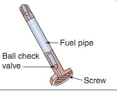
FIG. 24 A typical fuel pipe.
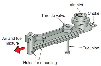
FIG. 23 The vacuum type carburetor uses a simple, one-piece housing.
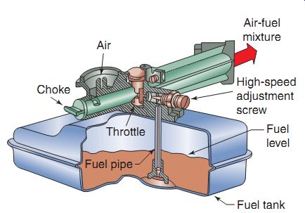
FIG. 25 Fuel delivered to the engine with a vacuum type carburetor.
Vacuum Carburetors
The vacuum carburetor, also called the suction carburetor, is a common carburetor often found installed in smaller, less expensive engines. A vacuum carburetor uses vacuum to pull fuel out of the fuel tank and mixes it with air entering the engine. These carburetors are always mounted on top of the fuel. All vacuum carburetors work the same basic way.
A vacuum carburetor has a simple one piece housing (FIG. 23). The housing is basically a tube with an opening at one end for intake air to enter. A choke valve in the air opening can be opened or closed to regulate air flow. The other end of the housing acts as an outlet for the air-fuel mixture. The mixture goes through the outlet and enters the engine intake port. This end has holes to mount the carburetor to the engine.
There is a throttle valve inside the carburetor just past the air entrance. Below the throttle valve is a tube called the fuel pipe (FIG. 24). The fuel pipe brings fuel up into the carburetor from the fuel tank. The bottom of the fuel pipe has a small screen that filters dirt from going up the pipe and into the carburetor. A small ball check valve fits in the bottom of the pipe. The ball check valve allows fuel to go up the pipe but will not let fuel run back out of the pipe.
The fuel tank fits on the bottom of the carburetor. The carburetor fuel pipe goes down into the bottom of the fuel tank. The cap on the fuel tank is vented to allow atmospheric pressure into the tank. Without a vent, a vacuum could form in the tank, which would prevent fuel from going up the fuel pipe.
A low pressure (vacuum) is created inside the carburetor as the piston moves down on the intake stroke. This low pressure pulls fuel up the fuel pipe (FIG. 25). The throttle valve is in the way of the flow of air entering the carburetor. It creates a low pressure area, as in a venturi. The low pressure helps pull fuel up the fuel pipe. The fuel is mixed with the intake air passing through the carburetor housing. The amount of fuel that comes out the fuel pipe is regulated by a high-speed fuel adjustment screw.
There are two circuits in the carburetor housing: low speed and high speed (FIG. 26). Fuel flows through either or both these circuits, depending on the speed of the engine. When the throttle plate is open, there is maximum flow out of both circuits. When the throttle plate is closed, only the slow-speed circuit allows fuel to flow. This circuit allows a small amount of fuel flow for idle, which allows the engine to run with a nearly closed throttle.
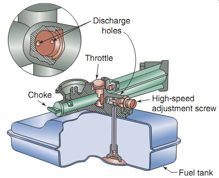
FIG. 26 Discharge holes are used in low- and high-speed circuits for the
fuel system in a vacuum type carburetor.
FIG. 27 A float type carburetor. The float bowl is on the bottom of the
carburetor.
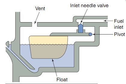
FIG. 28 A typical float chamber.
Float Carburetors
Many power equipment engines use a float carburetor (FIG. 27), which is a carburetor that has an internal fuel storage supply controlled by a float assembly. The fuel tank on the float carburetor system is attached to another part of the engine, often mounted higher than the carburetor.
Gravity causes fuel to flow from the tank through a fuel line to the carburetor. Some engines use a fuel pump to transfer the fuel from the tank, to the carburetor. A float assembly in the carburetor controls the flow of fuel from the tank.
The fuel line from the fuel tank provides fuel to the carburetor. The fuel line is connected to a carburetor fuel inlet fitting. The fuel flows past an inlet seat. The inlet seat is a carburetor part that houses and provides a matching seat for the tapered end of a float needle valve. The fuel goes through the inlet seat into the carburetor float bowl. The valve is used to allow fuel to flow or stop the flow of fuel into the float bowl. A float pivots against the needle valve (FIG. 28).
The float bowl is a component that provides a storage area for fuel in the carburetor. There is a small vent in the top of the bowl to allow atmospheric air in. The float is a component that floats on top of the fuel and controls the amount of fuel allowed into the float bowl. It shuts off the flow of fuel once the float rises far enough and "seats." Once the float rises and the needle seats, fuel is no longer allowed to flow into the float bowl.
As the engine runs, fuel in the float bowl is used up. The fuel level in the bowl drops. As the fuel level drops, the float drops. When the float moves down, the inlet needle valve connected to it moves out of the inlet seat. Fuel is allowed to come in through the inlet passage from the fuel tank. The fuel level rises as more fuel comes into the bowl. The float also rises, pushing the inlet needle valve into the inlet seat. This action repeats itself to maintain the required level of fuel in the float bowl (FIG. 29).
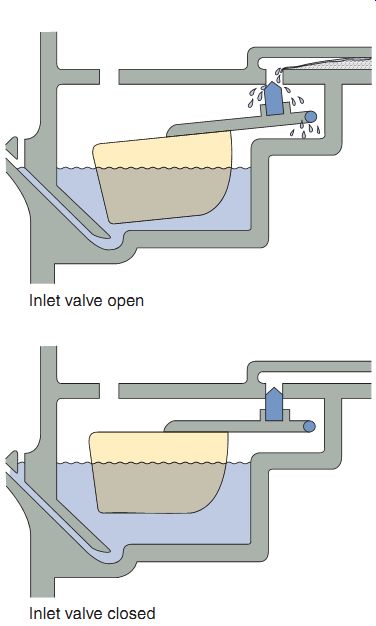
FIG. 29 A functioning of a typical float valve.
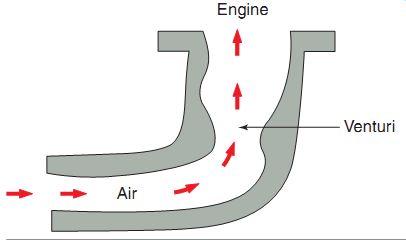
FIG. 30 An updraft float carburetor system.
Float Carburetor Types
All float carburetors use a float to control the fuel level. There are, however, different styles of float carburetors.
These carburetors are identified commonly by the direction of air flow into the carburetor throat. A carburetor throat is the part of the carburetor that directs air flow in toward the venturi.
Updraft, downdraft, and side-draft are common float carburetor designs. An updraft carburetor (FIG. 30) is a carburetor in which the air flows into the venturi in an upward direction.
Updraft carburetors are installed commonly in older, larger engines.
A downdraft carburetor (FIG. 31) is a carburetor in which the air flows into the venturi in a downward direction. Downdraft carburetors are used in some multiple cylinder engines. An intake manifold is used to connect a downdraft carburetor to the intake ports of each cylinder.
A side-draft carburetor (FIG. 32) is a carburetor in which the air flows into the venturi from the side. The sidedraft carburetor is common and is used in many sizes and styles of engines.
Float Carburetor Operation
Most float carburetors operate in the same fashion. The operation of the carburetor can be divided into different systems:
Float operation Idle (low-speed) circuit operation Part throttle circuit operation (transition from low speed to high speed) Main (high-speed) circuit operation The float system operates at all times and at all engine speeds (FIG. 33). It provides fuel for all the carburetor circuits. Fuel flows from the fuel tank to the carburetor by gravity or a fuel pump. Fuel enters the carburetor through the inlet fitting. It goes past the inlet needle valve and begins filling the carburetor bowl.
As the bowl fills, the float rises, raising the inlet needle valve toward the inlet seat (FIG. 34). When the inlet needle closes, fuel flow into the bowl stops. Fuel remains at this level until engine operation begins to draw fuel from the bowl. When the fuel level drops again, the float moves down, causing the inlet needle valve to move away from the inlet seat. Fuel again flows into the float bowl. This happens over and over to provide a constant fuel supply.
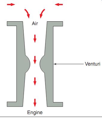
FIG. 31 A downdraft float carburetor system.
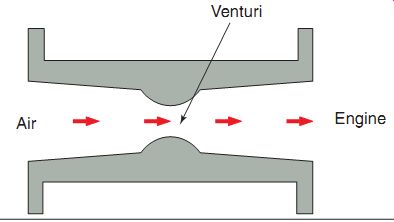
FIG. 32 A sidedraft float carburetor system.
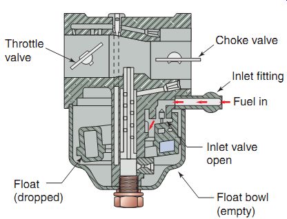
FIG. 33 Fuel flows into the float bowl when the float bowl is low (dropped).
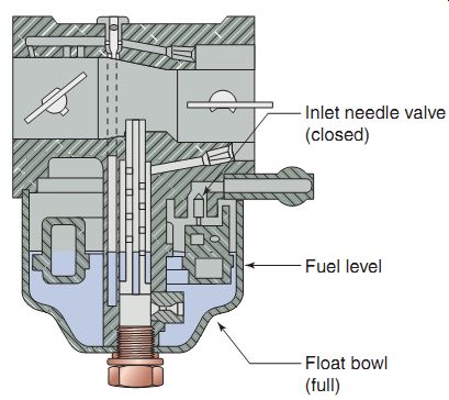
FIG. 34 When the float bowl is filled, the flow of fuel is stopped.
When the engine is idling, the throttle valve is in the closed (or nearly closed) position. The idle circuit delivers air-fuel mixture to the intake port side of the throttle valve (FIG. 35). Without this system, the engine would not run at idle speed.
When the cylinder is on an intake stroke, a low-pressure area is created in the intake port.
The carburetor throttle plate area also has low pressure at this time. Higher atmospheric pres sure in the carburetor bowl pushes fuel through a fixed-sized, high-speed jet through the low pressure area. Fuel continues up a small passage called the idle passage.
The atmospheric pressure from the intake stroke also pulls air into the throat of the carburetor. Some of this air goes through a passage called the idle air bleed. As the fuel comes up the idle passage, it enters the center of the idle speed jet. Here it mixes with air from the idle air bleed. The air-fuel mixture is then pulled through a passage, called the primary idle port.
It then goes into the carburetor throat. Here, it mixes with air flowing through the carburetor throat and goes into the engine's cylinder.
When an operator wants a speed increase, the throttle linkage is used to open the throttle valve. The carburetor uses the part throttle system (FIG. 36) when the throttle valve is open part of the way. The part throttle system has the same air-fuel flow as the idle system, with one exception. There are several secondary idle ports in the carburetor throat. These are uncovered as the throttle plate opens. The secondary ports give additional routes for the air-fuel mixture for part throttle engine speeds. The part throttle system can operate momentarily as the throttle passes from idle to high speed. It can also operate continuously if the throttle stays in the part throttle position.
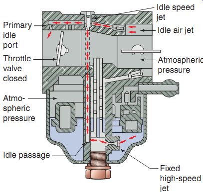
FIG. 35 A typical idle circuit.
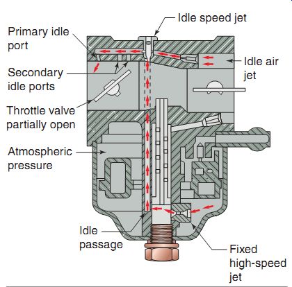
FIG. 36 The secondary idle ports are used to assist when the user applies
an increase in throttle.
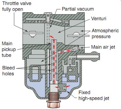
FIG. 37 The high-speed circuit comes into play when the throttle valve
is opened over half way.
When the operator moves the throttle link age past the part throttle position to more fully open position, the carburetor uses the high speed system (FIG. 37). The intake stroke causes a low pressure in the carburetor throat. Atmospheric pressure pulls air through the venturi in the middle of the carburetor throat.
There is a drop in pressure at the venturi. Atmospheric pressure pushes fuel through the fixed high-speed jet. From there, it goes through a large passage called the main pickup tube.
Atmospheric pressure also pushes air through a large air passage, called the main air bleed.
From this, air flows to the outside of the main pickup tube. This air enters through the main pickup tube bleed holes. There, it mixes with the fuel coming up the inside of the main pickup tube. The air-fuel mixture is pushed up and out of the main pickup tube into the incoming air at the venturi.
Diaphragm Carburetors
A diaphragm carburetor (FIG. 38) is a carburetor that has a flexible diaphragm to regulate the amount of fuel available inside the carburetor. It can be operated in any position.
Float- and vacuum-type carburetors work only in engines that are used in the upright position. For this reason, an engine equipped with a float or vacuum carburetor cannot be turned on its side or upside down, in which case the float or fuel tube would not be able to regulate the fuel level, and the engine would run out of fuel and stop. Handheld outdoor power equipment such as a chainsaws, leaf blowers, and string trimmers, which must work in any position, use engines equipped with diaphragm carburetors, as they can operate in any position.
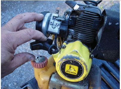
FIG. 38 A diaphragm carburetor can be turned in any angle without impairing
operation.
Diaphragm Carburetor Operation
The diaphragm carburetor is, in many ways, very much the same as a float carburetor. It has a throat, throttle valve, and venturi. But the diaphragm carburetor does not have a float bowl.
Instead, it uses a diaphragm similar to that used in a fuel pump. The diaphragm controls a small amount of fuel in a fuel chamber. A fuel inlet needle valve similar to that in a float carburetor is used to control fuel flow into the carburetor (FIG. 39).
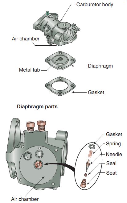
FIG. 39 The parts of a diaphragm carburetor.
The diaphragm is made from a flexible, rubber-like material. It's stretched across a small space above the diaphragm, called a fuel chamber. The center of the diaphragm has a metal tab (or lever in some designs) that contacts the inlet needle valve. The inlet needle valve works the same way as the needle valve in a float carburetor. The space below the diaphragm is called an air chamber, which has an air vent that allows air at atmospheric pressure below the diaphragm. The air chamber provides the space for diaphragm up-and-down movement (FIG. 40).
As fuel flows from the fuel tank to the fuel inlet, the spring pushes down on the control lever, causing the needle valve to drop down and allowing fuel to come in around the inlet needle valve. As the fuel fills up the chamber, its weight pushes down on the diaphragm (FIG. 41). Downward movement of the diaphragm causes the control lever to pivot upward. This movement pushes up on the inlet needle valve, closing the fuel inlet (FIG. 42). When fuel is used up, the diaphragm comes back up, allowing the inlet needle valve to open to let fuel in again.
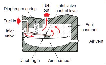
FIG. 40 A diaphragm carburetor has two chambers: one for fuel and one
for atmospheric pressure.
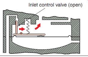
FIG. 41 The inlet valve of the diaphragm carburetor in the open position.
As fuel enters the chamber, it pushes down on the diaphragm.
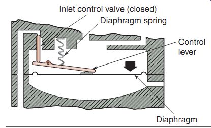
FIG. 42 Once fuel has filled the chamber
of the diaphragm carburetor, the inlet control
valve closes off the flow of fuel, just as on a
float type carburetor.
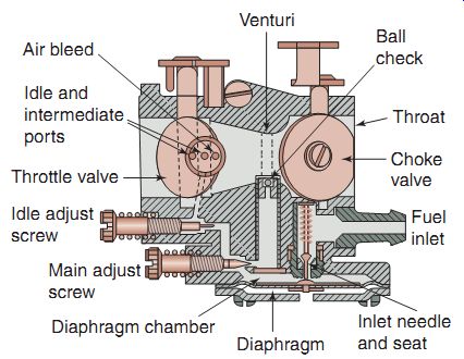
FIG. 43 The various circuits of a diaphragm carburetor.
Many diaphragm carburetors use two diaphragms: one to control the fuel flow into the carburetor and the other as an impulse fuel pump. The pump section pumps fuel from the fuel tank to the carburetor.
Modes of Operation of a Diaphragm
Carburetor Just as with every other type of carburetor, the diaphragm carburetor provides the correct air-fuel mixtures for several modes (circuits) of operation (FIG. 43). These include:
- Cold starting
- Idle Intermediate speed
- High speed
When the engine is cold, a rich mixture is required for starting. The choke system has a valve in the carburetor throat, as we had discussed earlier in this section. In the choke mode, the choke valve is closed. The only air that can get into the engine enters through openings around the choke valve. When the engine is cranked during starting, the intake stroke creates a low pressure in the venturi. The low pres sure pulls fuel from the diaphragm chamber up the main nozzle. Fuel is also pulled from idle fuel discharge ports. The fuel mixes with the air that passes around the choke valve. A very rich air-fuel mixture is used to start the cold engine.
During idle speeds, only a small amount of fuel is needed to keep the engine running. The throttle valve is almost closed during idle. A small idle discharge port is located on the engine side of the closed throttle valve. The low pres sure in this area pulls fuel from the diaphragm chamber. Fuel goes past an idle adjusting screw and is delivered behind the throttle valve. The fuel is mixed with air that gets through the almost closed throttle valve. Additional air comes through an idle air bleed passage. The idle adjusting screw adjusts the amount of fuel that is delivered out the idle discharge port.
When the throttle valve is moved past the idle position, it uncovers two more discharge ports, called the intermediate ports. They pro vide more fuel to mix with the air flowing into the engine. The fuel flows from the diaphragm chamber past the idle mixture adjusting screw.
Fuel and air flows are the same as in the idle mode. The additional fuel from the intermediate ports allows the engine to operate at higher speeds.
The high-speed circuit is used when the throttle valve is opened further. Air flows through the carburetor throat at high speed. The venturi further accelerates the air flow and creates a low pressure in the venturi area. This low pressure pulls fuel into the air stream through a delivery tube called the main nozzle. Fuel flows into the main nozzle through a passageway from the diaphragm chamber. Fuel going up the main nozzle must pass the main adjusting screw, which is used to adjust the amount of fuel for high-speed operation.
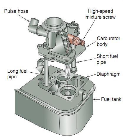
FIG. 44 The suction feed diaphragm carburetor is one that combines the
features of a vacuum carburetor and the impulse fuel pump.
Suction Feed Diaphragm Carburetors
The suction feed diaphragm carburetor is a carburetor that combines the features of a vacuum carburetor and the impulse fuel pump (FIG. 44). This carburetor is used primarily in four-stroke engines. These engines are not usually used in a variety of positions. The carburetor is mounted on the top of the fuel tank.
It meters fuel the same way as the vacuum carburetor. Some carburetors have the diaphragm mounted in a side chamber. Others have the diaphragm located between the carburetor body and the fuel tank.
This carburetor is different from the vacuum carburetor. It has two different-length fuel pipes (FIG. 45). The longer fuel pipe goes into the fuel tank and is used to pull fuel out of the tank and into a small chamber. The shorter fuel pipe goes into a small chamber of the fuel tank. The chamber is called the fuel cup or fuel well. A diaphragm fits between the carburetor and the fuel cup. The diaphragm works like an impulse fuel pump, transferring fuel between the tank and the fuel cup (FIG. 46). This system gives a constant level of fuel, regardless of fuel tank level.
A pulse hose connects the pumping chamber to the intake manifold (or crankcase in some designs). When the engine is running, the pulse hose transmits a pulse to the diaphragm chamber. The diaphragm moves up and down with the pressure pulses, pumping fuel up the long- fuel pipe into the fuel tank cup. Fuel goes out of the fuel cup into the venturi through the short- fuel pipe.
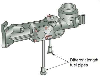
FIG. 45 The suction feed diaphragm carburetor has two, different-length
fuel pipes.
The longer fuel pipe goes into the fuel tank and is used to pull fuel out of the tank. The shorter fuel pipe goes into a small chamber of the fuel tank.
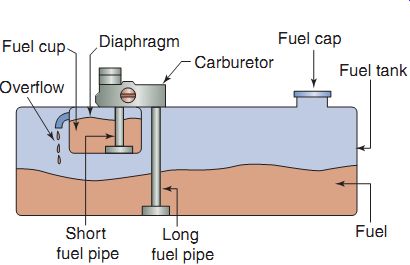
FIG. 46 The suction feed carburetor drawing fuel from the fuel tank.
FUEL INJECTION
Fuel injection is the most modern method for carburetion in today's power equipment engines. The purpose of fuel injection is to allow a precise metering of air-fuel mixture ratios at any given engine condition. This results in the engine getting only the amount of fuel it needs at all times, instead of a preset amount being delivered at all times, as with traditional carburetors. Other than the method of getting fuel into the engine, the basic components of this system aren't much different from those of a standard carburetor engine. In today's power equipment engines, fuel injection is relatively new but is becoming popular as using it leads to easier compliance with the strict guidelines of the United States Environment Protection Agency (EPA). Compliance ensures that the air we breath remains as clean as possible, by ensuring that our modern power equipment engines are as fuel efficient as possible-combustion wise-while setting a performance level unlike anything we've seen in the past.
The primary advantage of fuel injection over traditional carburetion is the ability of a fuel injected engine to automatically adjust to the constantly changing atmospheric conditions to which it's exposed. Conditions such as tempera ture, humidity, and altitude affect traditional carburetion, altering the efficiency of a carbureted power equipment engine, unless one were to make physical adjustments to the carburetor settings. But with an engine using fuel injection systems, these conditions are compensated for by the use of sensors found within the fuel injection system.
The disadvantage of fuel injection? Cost. Due to the high cost of fuel injection systems, almost all small power equipment engines continue to use carburetors, whereas larger engines are beginning to move up to the higher technology of fuel injection.
The primary type of fuel injection found in today's power equipment engines is called indirect fuel injection. There is also another type of system known as direct fuel injection.
Direct Fuel Injection
With the direct fuel injection system, fuel is injected directly into the combustion chamber.
This type of fuel injection is found primarily in diesel engines and not generally found in power equipment engines. The direct system injects an extremely fine mist of fuel into the combustion chamber just prior to the top-dead center (TDC) of the engine's compression stroke.
Indirect Fuel Injection
The indirect fuel injection system is the most common type of fuel injection system found in power equipment engines. When an indirect fuel injection system is used, fuel is injected into the intake tract before the intake valve. All modern fuel-injected power equipment engines use a type of electronic fuel injection (EFI). Some manufacturers may use different terms to refer to EFI: computerized fuel injection (CFI) or programmed fuel injection (PGM-FI). All these systems use an electronic control module (ECM) to control the amount of fuel being delivered to the engine.
Indirect EFI systems give engines the ability to provide excellent performance as well as meet future EPA standards-standards that are getting tougher to achieve with each passing year.
Fuel Injection System Components
Although most small power equipment engines don't use fuel injection now, their use in future is inevitable. Therefore, we'll summarize a description of the components found in a typical EFI system. Let's start our discussion on EFI-related system components with the area of fuel delivery.
Fuel Pumps
Fuel pumps used with electronic fuel-injected power equipment engines have three primary requirements:
They must be electric powered. They must have the ability to handle a high volume of fuel.
They must have the ability to supply high pressure to the injectors.
Many modern power equipment engine EFI fuel pumps are located inside the fuel tank of the power equipment engine to save space as well as to prevent vapor lock, a condition that is caused when gasoline overheats and begins to actually boil within the fuel pump. An ECM controls the operation of the fuel pump. The fuel pump will generally operate for a couple of seconds after the key is first turned on to pressurize the fuel injectors.
The fuel pump consists of an electric armature that spins between two magnets and turns an impeller that draws fuel in and through the pump (FIG. 47). A check valve is incorporated to maintain pressure at the fuel injectors to allow for quick engine starts. Fuel is sealed in this system and therefore cannot evaporate or deteriorate during long periods of nonuse, as during winter months. A relief valve is also located within the fuel pump and is opened to send fuel back into the fuel tank if a fuel line were to become restricted and cause excessive pressure buildup.
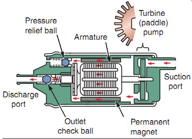
FIG. 47 The components of an electronic fuel pump for a fuel injection
system.
Fuel Filters
There are generally at least two fuel filters used in EFI systems. Before fuel enters the fuel pump, it must go through a mesh filter that prevents grit and rust from entering the pump and damaging it. Another filter used is a large inline type and can be mounted inside or out side the fuel tank (FIG. 48). The operation of fuel filters is critical in a fuel-injected system because clogged fuel injectors won't function properly.
Fuel Lines
EFI systems use special, high-pressure fuel lines from the fuel pump to the injectors, which can be damaged by mishandling due to excessive bending or stretching. The damage in many cases will be internal and therefore you'll not see it until the line breaks under pressure. When servicing EFI power equipment engines, be sure to adhere to the appropriate service manual to avoid damaging the fuel lines.
Fuel Pressure Regulators
The fuel pressure regulator maintains correct fuel pressure and keeps it above the pres sure of the intake manifold. Excessive pressure is returned to the fuel tank by a separate return hose (FIG. 49).
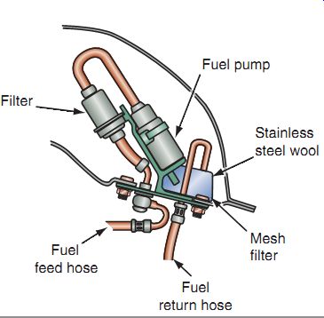
FIG. 48 The fuel filters located inside the fuel tank.
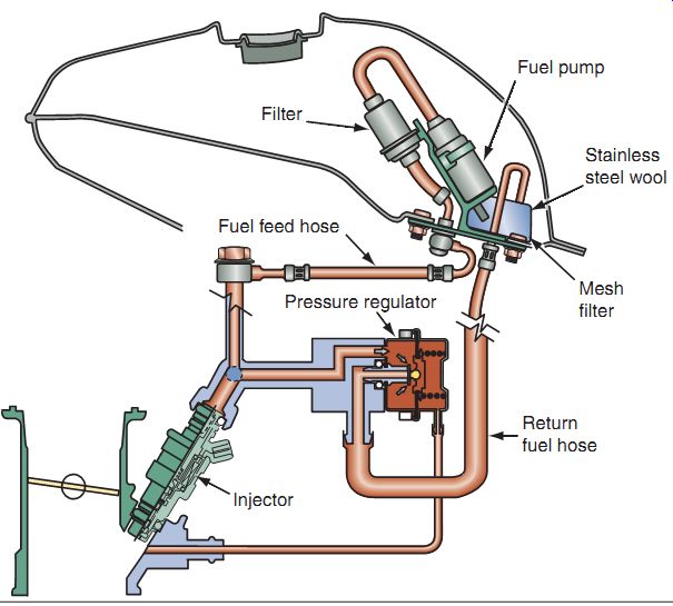
FIG. 49 A fuel pressure regulator is used to maintain correct fuel pressure
and keep it above the pressure of the intake manifold.
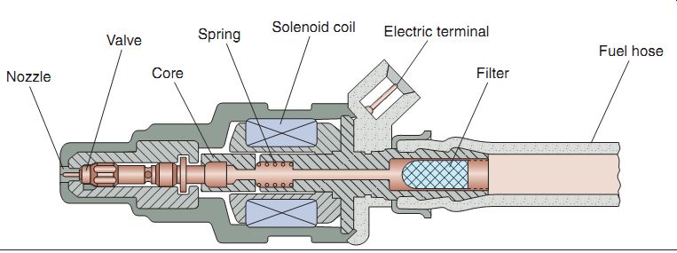
FIG. 50 The fuel injector is a solenoid that is either on (fuel flows)
or off (fuel does not flow).
Fuel Injectors
The fuel injector is an electronically operated solenoid that turns fuel on and off (FIG. 50). They're generally closed and are either fully closed or fully open. The ECM "tells" the fuel injector when to turn on and off. The control unit also determines how long the injector must stay on, therefore telling the injector how much fuel has been injected into the engine.
This is known as injector discharge duration.
The length of time for which the fuel injector is turned on is known as discharge duration. Three factors influence fuel atomization in an EFI system: the shape of the injector, fuel pressure, and turbulence in the air intake tract. Inside the injector, there's a spring-loaded plunger that closes against a valve seat. Once seated, the flow of fuel is blocked. When the solenoid coil within the injector assembly lifts the plunger, the pressurized fuel sprays into the cylinder. A battery supplies the power for the solenoid coil, and the ECM controls the ground side of the injector, therefore making the injectors "switch to ground circuits." Each injector is controlled by the ECM, and fuel is delivered to the cylinder only as it's needed. This is known as sequential fuel injection.
Fuel injector tip openings are designed to provide a spray pattern that atomizes the fuel to help it mix with the incoming air. There are different types of fuel injector tips, the most common having a single outlet, although some engines use multiple outlets (FIG. 51). These outlet designs are used to vary the spray pattern to the manufacturer's design needs for different performance requirements as well as manufacturing costs.
Fuel Injector Failures
Fuel injectors can have two types of failures: electrical and mechanical.
There are three possible electrical failures for an injector:
High resistance
An open electrical circuit; one in which cur- rent cannot complete its path A short circuit; one in which current takes an unintended path
Some power equipment engines can detect electrical failures while the machine is running. Others can detect a failure only when they're started.
There are two possible mechanical failures for an injector:
Leaking fuel (partial or complete)
Blocked fuel discharge (partial or complete)
Possible fuel leakage is indicated by:
Dark spark plug color
Fuel fouled spark plugs
Blocked fuel discharge is indicated by:
A cold exhaust pipe on that cylinder
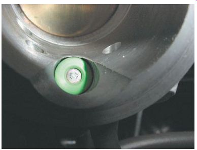
FIG. 51 Various types of tips can be found on a fuel injector. Decisions
on the type of injector to be used can be based on intended use as well as
cost.
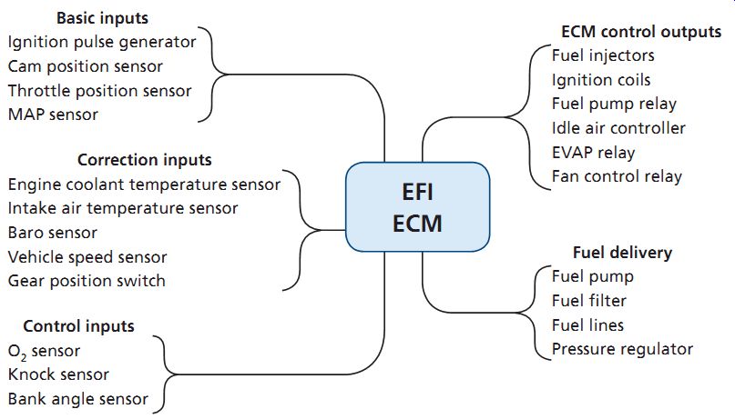
Table 2 Typical inputs for an electronic fuel injection
ECM
The heart of all fuel injection systems is the ECM. The ECM receives signals from all the EFI system sensors, processes them, and transmits programmed electrical pulses to the fuel injectors. Both incoming and outgoing signals are sent through a wiring harness and a multiple-pin connector. The ECM uses a micro computer to process data and control the operation of the fuel injectors, ignition spark and timing, and the fuel pump. The ECM receives information from basic input sensors and determines what, when, why, and how long the various operation steps need to be controlled.
Depending on the manufacturer, an ECM can also be called an electronic control unit (ECU).
ECM Inputs and Outputs
The ECM has three types of inputs (Table 2):
Basic Correction Control
The basic inputs provide information that the ECM needs to select a particular mixture control map (most EFI systems have at least two maps). The ECM then selects the basic fuel discharge duration from the chosen map. Basic inputs include ignition pulse, camshaft position sensor, throttle position sensor, and the vacuum pressure in the intake manifold [manifold absolute pressure (MAP) sensor].
The correction inputs provide the information that the ECM needs to adjust the basic fuel discharge duration. Typical correction inputs would include engine temperature, intake air temperature, barometric pressure (BARO), and vehicle speed.
The control inputs provide the information that the ECM needs to adjust engine operation.
These inputs would be the oxygen sensor and knock sensor. A bank angle sensor is used often in power equipment engines to cut off electrical power to the ECM in the case of the machine tipping over. Bank angle sensors are designed to stop the engine.
ECM outputs include the fuel injection, ignition spark as well as the operation of the fuel pump and cooling fan in liquid-cooled machines.
Sensors
Various sensors monitor the engine and atmospheric conditions such as throttle position, engine revolutions per minute (rpm), engine and intake air temperature, vehicle speed and MAP (which is calculated into air density), coolant temperature, and piston position. These sensors assist in all aspects of EFI and send information to the ECM to allow the engine to run as efficiently as possible.
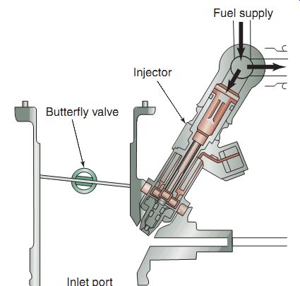
FIG. 52 A throttle body for an electronic fuel injection (EFI) system
along with an illustration of a fuel injector and the inlet port of the throttle
body.
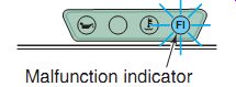
FIG. 53 The malfunction indicator light (MIL) will let a user know if
a failure is detected in the EFI system.
Throttle Body
Engines with PGM-FI may have one throttle valve for each cylinder. The throttle body contains the injector as well as a butterfly valve (FIG. 52). Power equipment engines with EFI don't need to depend on the Venturi effect because of the fuel injector delivery of a precise amount of fuel at any given time, unlike a carbureted power equipment engine that will receive the same amount of fuel at all throttle openings.
EFI Self-Diagnostics
Most modern power equipment engines that use EFI have a self-diagnostic system incorporated to assist technicians when problems arise. Various components on EFI are monitored continuously by the self-diagnosis function and if the ECM notices a fault, a light comes on within the dashboard of the machine.
This light is sometimes called the "check engine" light or the "FI" light. Some manufacturers call this light by the term officially used in the auto motive industry, which is the malfunction indicator lamp (MIL) (FIG. 53), and depending on the severity of the fault, may give a warning to the user. In other cases, the engine may go into a fail-safe operation mode, which allows the engine to continue to run but at a reduced performance level or stop completely, depending on the severity of the fault, such as when an electrical-related problem is detected by the system sensors. The MIL is used to detect and assist in diagnosing any EFI-related, electrical failure.
Basic Operation of the Fuel
Injection System In a typical EFI system, the ECM must "know" the amount of air entering the engine so that it can supply the stoichiometric air-fuel ratio. Most EFI systems have a MAP sensor to allow the computer to calculate the amount of air entering the engine from the MAP and engine rpm input signals. The ignition pickup or crankshaft position sensor supplies an rpm signal to the computer. The MAP sensor sends a signal relating to the pressure inside the intake manifold to the ECM. The computer must have accurate signals from these inputs to maintain the stoichiometric air-fuel ratio. Other inputs are used by the computer to fine-tune the air-fuel ratio through electronic feedback.
Electronic feedback means the system is self regulating and the ECM is controlling the injectors on the basis of operating conditions rather than on preprogrammed instructions. As an example of a feedback loop used in many EFI systems, the ECM reads signals from an oxygen sensor, varies the pulse width of the injectors, and again reads the signals from the oxygen sensor. This cycle is repeated until the injectors are pulsed for just the amount of time needed to get the proper amount of oxygen into the exhaust stream. While this interaction is occurring, the system is operating in a closed loop.
During the closed-loop mode, sensor inputs are sent to the ECM; the ECM compares the values with those in its programs and then reacts to the information to adjust the air-fuel ratio and other engine systems.
When conditions such as starting or wide open throttle demand that the signals from the oxygen sensor be ignored, the system operates in an open loop. During open loop, injector pulse length is controlled by set parameters contained in the ECM's memory. Systems with oxygen sensors may also go into the open-loop mode while idling or at any other time that the oxygen sensor cools off enough to stop sending a good signal, and at wide-open throttle.
The basic purpose of these control loops is to create an ideal air-fuel ratio, which allows engines using catalytic converters to operate at maximum efficiency while giving the best fuel mileage and performance possible. A catalytic converter is a device used to reduce the toxicity of emissions from an engine.
Summary
Fuel has different octane ratings and various factors affect these ratings.
The primary principles of carburetor operation are atomization, the process of combining air and fuel to create a mixture of liquid droplets suspended in air, and the Venturi principle, which states that a gas or liquid that's flowing through a narrowed down section of a passage will increase in speed and decrease in pressure compared with its speed and pressure in wider sections of the passageway.
Fuel delivery systems consist of many separate components, and servicing fuel delivery systems involves inspecting and cleaning or replacing many of these components.
Each type of carburetor has different components that function similarly.
The purpose of fuel injection is to allow an extremely precise metering of air-fuel mixture ratios at any given engine and atmospheric condition.
QUIZ
1. Gasoline by itself as a liquid will not burn. (True/False)
2. The air we breathe contains , which is used to help ignite the fuel mixture in an engine.
3. The rating is defined as the fuel's ability to resist detonation in an engine.
4. The choke plate cold start system controls the amount of entering the carburetor.
5. Carburetor circuits overlap one another. (True/False)
6. The fuel pump in an electronic fuel injection system is or powered.
7. The amount of time that the fuel injector is open is known as ___.
8. Sensors in a fuel injection system monitor the throttle position, air volume, and other important engine parameters, transmitting this information to the or ___.
9. An electronically operated solenoid in a fuel injection system that turns fuel on and off is called a .
10. You should not clean a paper air filter with soap and water as it will damage the paper fibers. (True/False)