AMAZON multi-meters discounts AMAZON oscilloscope discounts
Goals:
- Define the four key purposes of lubrication
- Describe the types of lubricating oils and how they're classified
- Explain why bearings, bushings, and seals are needed in an engine
- Identify the different types of bearings used in power equipment engines
- State the purpose of two-stroke and four-stroke engine lubrication systems
- Identify the different types of lubrication systems used in two-stroke and four-stroke power equipment engines
- Describe how cooling systems work and why they're used
- Identify the components of power equipment cooling systems
- Identify the various specialty lubricants used in lubrication system maintenance
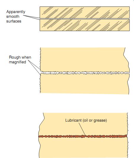
FIG. 1 Engine parts that seem very smooth may actually be quite rough
when viewed under magnification. Lubricants provide a cushion to prevent the
rough edges of component parts from making contact with each other.
INTRODUCTION
Both two-stroke and four-stroke engines used in power engine equipment have many moving internal parts that are machined to extremely tight tolerances. To the naked eye, these parts have a smooth, fine finish, which is required to optimize wear inside the engine. However, if you were to look at these parts under a microscope, you would see that these seemingly smooth parts are actually quite rough! To reduce the friction that occurs if two or more of these surfaces make contact, it's necessary to maintain a thin layer of lubrication between them (FIG. 1).
A thin layer of lubricant between all internal engine parts effectively separates the parts from each other and provides a slight cushion for them to rest against. A lack of lubrication between these parts causes an immediate buildup of excessive heat and in extreme cases, causes the parts to actually melt together. When two or more parts inside an engine are hot enough to melt together in this manner, we say an engine seizure has occurred.
In addition to its role as a lubricant, oil inside an engine performs many other functions. The oil film that coats each internal part keeps air and moisture from the parts, thereby preventing the buildup of corrosion. Also, when used in the four-stroke engine, oil is constantly recirculated, carrying away contamination and trapping it in an oil filter. Oil is also used to aid in the creation of seals in two-stroke and four-stroke engine parts that require additional sealing. Finally, oil helps to disperse the heat generated in high temperature areas such as the piston, cylinder, transmission, and combustion chamber.
Although power equipment engines built today are quite efficient, they still waste a considerable amount of energy. Ideally, a 100% efficient engine would convert all the heat energy it produces into mechanical energy. Unfortunately, there's a considerable amount of heat energy produced in engines that's not converted to mechanical energy, thus creating engine heat.
It's the job of the lubricants and the engine lubrication and cooling systems to remove the unwanted heat, thus preventing engine damage.
Now, let's learn about lubricants, lubrication systems, and cooling systems used in the engines found in power equipment.
The importance of an engine's lubrication system and the lubricants used in power equipment engines can't be overemphasized. If proper lubricants are missing or the engine's lubrication system is operating improperly, the moving parts inside the engine will get hot enough to actually melt together, as mentioned earlier.
These internal engine components can score or even lock together in a matter of minutes. The buildup of heat, caused by friction, is one of the worst enemies of the engine.
This section will give you an understanding of the types of lubricants and lubrication systems used in power equipment engines. It covers both two-stroke and four-stroke engine designs.
You'll learn how bearings, bushings, and seals help control and reduce friction. In addition, we'll discuss lubrication requirements for components of the engine found in power equipment. You'll also learn about the specific cooling systems used in power equipment engines.
LUBRICANTS AND LUBRICATION
An engine has two main enemies: friction and heat. The main purpose of lubrication is to reduce friction. What is friction? Friction is the resistance to motion created when two surfaces move against each other, or when a moving surface moves against a stationary one. To understand what we are talking about here, take a moment and rub your hands together quickly, pushing against them as hard as you can. Feel the heat? That's friction! Now, do the same thing with one hand against any stationary object, like an arm on a chair. Then repeat the action with some lotion on your hands and you can feel the difference lubrication makes! Friction can occur in many places in a power equipment engine.
Some of these places are the:
Cylinder wall, where the piston and piston rings rub wrist pin and mating surfaces of the piston and connecting rod
Crankshaft pin, bearing, and connecting rod
Teeth of any gear inside the engine
Camshaft lobes, valve guides, and valve stems (in four-stroke engines) If these surfaces are not protected by some form of lubrication, they will quickly heat up and wear.
The great amount of heat created inside the engine by friction places a strain on vital engine components. To prevent these parts from overheating, modern power equipment engines require high quality lubricants. Lubricants and engine lubrication systems used in modern power equipment engines have been greatly improved over the years, thanks to the research done by power equipment engine and lubricant manufacturers. The useful life of an engine without proper lubrication might be measured in minutes; the service life of a properly lubricated engine can be thousands of hours!
Lubrication serves four key purposes. When used properly, a lubricant will: Cool, Clean, Seal , Lubricate to reduce friction
Cooling
When oil in the engine flows through oil passageways or splashes within the engine, it helps cool the internal engine components by absorbing heat from the metal parts. The circulating hot oil is then returned to the engine's crank case, where it's cooled.
Cleaning
While the oil is moving around and through the internal engine components, it's also cleaning the engine's parts. Combustion and nor mal wear and tear of engine parts produce tiny metallic particles and other contaminants.
Today's engine oils contain special additives that help hold these contaminants in suspension until they can be removed. The lubrication system removes contaminants as it passes oil through the engine's oil-filtering system. The oil filter system can't remove all the contaminants in the oil; those remaining are removed by draining the engine oil. This is why oil turns darker in color after hours of use.
Sealing
Another function of engine oils is to help the piston rings seal in engine compression and combustion pressures. A thin oil film between the piston rings and cylinder wall is essential for the rings to seal properly. Oil between the piston ring groove and piston rings also aids in preventing combustion pressure leakage. Oil on engine parts also protects the components from corrosion and moisture.
Lubricating
It should now be clear that power equipment engines consist of many internal components and parts that contact each other as they move. As a result of this contact, a certain amount of friction and heat is always present. The main purpose of oil in a lubrication system is to help reduce friction by keeping a thin layer of oil between all the engine parts.
This thin film of oil helps to prevent excessive metal-to-metal contact and unwanted friction.
Remember, friction is the resistance to movement between two surfaces. A lubricant helps to reduce friction and the heat that friction produces. Lubricants thus reduce engine component wear.
Types of Engine Oils
In today's power equipment engines, selecting suitable lubricating oil is very important.
Power equipment engine and oil manufacturers have worked hard to develop oils that meet and even exceed the high demands of power equipment engines. There are three basic types of oils used in today's engines.
Petroleum-Based Oils
The first type of oil is standard mineral based oil, more widely known as petroleum based oil. Petroleum-based oil starts out as crude oil, located in large underground pools all over the world. After this oil is removed from the ground, it's heated in a process known as fractional distillation. This process separates the needed lubricating oil from other elements within the crude oil. The oil is then blended with other additives to adjust its viscosity to desired levels. Viscosity is determined by the rate of oil flow under certain controlled conditions. High viscosity oils flow slower at room temperature than low-viscosity oils.

Table 1 Improving an oil's operating qualities
Standard petroleum-based oils perform poorly without additives. Oil additives are selected and used in the manufacturing of oils to improve the oil's operating qualities. Additives don't change the basic characteristics of oil; they just add new properties to it. Several additives are used in oil today; each is selected for a specific purpose. Table 1 lists the types of commonly used additives and the characteristics they impart to oil. One example of an engine oil additive is sulfur, which is used to improve the oil's extreme-pressure properties.
Another example is zinc, which is added to oil to increase its shear strength. Some desirable characteristics that result from the proper use of oil additives are higher film strength, resistance to foaming of the oil, resistance to oxidation of the oil, and the ability to keep oil contaminants in suspension. One important and interesting fact about standard mineral-based oils is that the base oils themselves don't wear out, only the additives do!
Synthetic-Based Oils
Another type of oil is synthetic-based oil.
Synthetic oils were developed during World War II, when petroleum products were not widely available. Today's synthetic oils operate more efficiently and over a larger range of temperatures, compared with standard mineral-based oils. When synthetic oils are manufactured, a variety of synthetic additives are added to help increase the oil's effectiveness. Advantages of using synthetic-based oils include the ability to handle higher engine temperatures before breaking down and less viscosity change with change in temperature.
The main disadvantage to using synthetic based oils is that it may not be compatible with some petroleum-based oils. Synthetic-based oils are also more expensive than petroleum based oils.
Petroleum-Synthetic Blended Oils Blended oils are popular today. They combine a petroleum base stock with synthetic additives, instead of petroleum additives. This combination greatly increases the quality of the oil. For this reason, blended oils are widely used in today's power equipment engines.
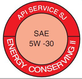
FIG. 2 All lubricating oils have labels showing a classification determined
by the American Petroleum Institute (API) and viscosity ratings by the Society
of Automotive Engineers (SAE).
Oil Classification
The internal combustion engine has become more sophisticated and technologically advanced over the years, thus increasing the operating requirements of engine oil. As a result, two general automotive agencies were established to test, standardize, and classify lubricating oils (FIG. 2): the American Petroleum Institute (API) and the Society of Automotive Engineers (SAE). These agencies classify oil on the basis of:
Manufacturer requirements regarding additives
Intended use of the oil
Viscosity ratings
Letter Classification Codes
Oil classifications use a double-letter code to indicate their intended use and manufacturer requirements. Oils used in power equipment gasoline engines have a code that begins with the letter S. The "S" stands for "spark" ignition engines. The lowest-grade oil for use in the gasoline engine has a classification of SA. Rarely used today, this type of oil is a petroleum-based oil containing no additives. This oil classification isn't recommended for use in any power equipment engine. Today's highest classification of oil is rated SM. Oils rated SE, SF, SG, SH, SJ, or SL are also recommended for use in power equipment engines. Most manufacturers today recommend oil rated "SG or higher" for their engines.
Table 2 shows the classifications used by the API. The API also classifies diesel engine oil. The letter code for diesel oil is C. The letter "C" stands for "compression" ignition engines.
Although you wouldn't use oil designed for a diesel engine in a power equipment engine, there are times when the same oil can be used for either engine. When this is the case, it's indicated on the API label. It's important to understand which oil to use in a particular power equipment engine. Engine service and owner's manuals contain the manufacturer's recommendation regarding oil usage.
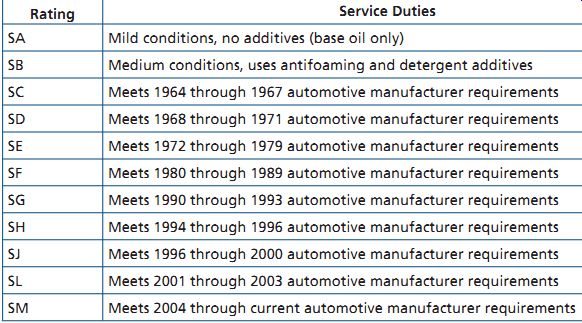
Table 2 API oil classifications
Engine Oil Weight Classifications
Let's now discuss oil weight and how the SAE measures it. The weight of oil is a reference to its thickness, from extremely thin oils of 0-weight, up to 90- or 140-weight oils. It's important to understand that a lower-number weight, such as 10-weight oil, is thinner than higher- numbered oil, such as 40-weight oil. The oil-weight numbering system tells us that, all conditions being equal, a 10-weight oil flows faster than a 40-weight oil when poured through holes of the same size at the same temperature.
To determine the viscosity of oil, it's poured through an orifice at a predetermined tempera ture. Two temperatures are used to test oil viscosity. For winter usage, oils are tested at 0° Fahrenheit (°F) and are marked with a "W" after the number to indicate "winter." All other oils are tested at a temperature of 210°F or higher. Keep in mind that the weight numbers indicate the oil's viscosity rating only. A higher numbered oil, such as a 50-weight oil, doesn't indicate better lubrication capacity than, say, a 10-weight oil. The weight of oil has nothing to do with its quality; it's a designation used for comparison purposes only.
So, what does this really mean? Different temperatures have a direct effect on oil viscosity. Oil tends to become thicker at lower temperatures; therefore, a lower weight number or a thinner oil should be used in cold weather conditions.
Extremely hot temperatures require a higher weight-numbered oil, or heavier, thicker oil.
Multi-Viscosity Oils
The majority of engine oils used in modern power equipment engines have designation numbers such as 10W40 or 20W50. This type of oil is called a multi-viscosity oil. These designations indicate oil viscosity that's suitable for use under many different climatic and driving conditions.
For example, 10W40-rated oil gives proper lubrication in both cold and warm conditions.
The 10-weight rating indicates that the oil will flow when the temperature is low (recall that the W stands for winter test). Protection is also pro vided as the temperature increases, as indicated by the 40-weight rating.
Multi-viscosity oils contain additives that allow the oil to work as a higher-weight oil at higher temperatures to improve the viscosity index. The viscosity index is the number used to indicate the consistency of the oil with changes of temperature. Oil labeled 10W30 is a 10-weight oil at 0°F, but has the viscosity of a 30-weight oil at 210°F. It's important to note that oils such as these are specially designed; thus, combining a straight 10-weight oil and 40-weight oil doesn't have the same effect as the factory-prepared 10W40 multi-viscosity oil.
The type or grade of lubricant best suited for any given power equipment engine component depends on many factors. Considerations include the type of power equipment engine running conditions, types of intended use, and weather conditions, such as dry, wet, or extremely hot. Power equipment engine manufacturers recommend a certain type or grade oil or lubricant for each specific component. It's best to follow the manufacturer's recommendations.
If these recommendations aren't readily avail able, check with the manufacturer or ask your local power equipment engine dealership. They can usually give advice that will help determine product suitability for the job at hand.
Specialty Lubricants
Now that you have a basic understanding of engine oils, let's briefly discuss other types of lubricants used in power equipment engines.
The type of specialty lubricant used depends on the component to be lubricated.
Grease
Grease is a lubricant that's suspended in gel. It's often used in non-engine-related components, such as wheel bearings and axles. Grease is designed for long-term lubrication.
Dry Lubricants
Dry lubricants are used to lubricate without attracting contaminants. These lubricants use an evaporating solvent as a carrier. Dry lubricants are often used on cables and areas that are in the open atmosphere.
Other Lubricants
You'll use many other types of specialty lubricants, such as silicone spray, penetrating oils, and multipurpose lubricants, on various parts of power equipment engines. These products are widely available and are used for every thing from helping to loosen rusted nuts and bolts to lubricating squeaky parts.
FRICTION-REDUCING DEVICES
The purpose of friction-reducing devices in an engine is, as the name indicates, to reduce friction. These devices, called bearings, are also used to reduce free-play between engine shafts, allow for proper spacing, and support different types of loads. Bearings can use either a rolling motion or a sliding motion to reduce friction. Examples of bearings that use a rolling motion are:
- Ball bearings
- Roller bearings
- Tapered roller bearings
- Needle bearings
Examples of bearings that use a sliding motion are:
Plain bearings Bushings
Keep in mind that the purpose of any bearing is to help reduce the buildup of friction between moving parts that are carrying a load.
Ball Bearings
Ball bearings are the most popular bearing used in power equipment engines because they provide the greatest amount of friction reduction and have the ability to handle both axial (side to side) and radial (rotating) loads.
Ball bearings consist of spherical balls contained in a cage and are held in place by inner and outer races (FIG. 3). The cage ensures the balls don't touch one another. Ball bearings require very little lubrication. They're used to support crankshafts in both the two-stroke and four-stroke engine cases, allowing the shafts to rotate freely.
Roller Bearings
Roller bearings are similar in design to ball bearings, except they use cylindrical-shaped rollers instead of spherical balls. The roller bearing is capable of withstanding higher radial loads than the ball bearing because of its greater avail able surface contact area.
Tapered Roller Bearings
FIG. 3 also shows a variation of the roller bearing, known as a tapered roller bearing.
The diameter of each roller of a tapered roller bearing is larger at one end than at the other.
Tapered roller bearings are normally used in pairs with opposing angles, such as in steering mechanisms.
Needle Bearings
Needle bearings are yet another variation of the roller bearing. The lengths of needles or rollers of a needle bearing are usually several times more than their diameters. Needle bearings normally have an attached cage, which keep the needles from making contact with one another. Needle bearings often have only an outer race. In this case, the needles make direct contact with the shaft surface they're supporting. Needle bearings can be found on some camshafts, and in almost all two-stroke engine connecting rods.
A key advantage of both the ball bearing and the roller bearing is that they can operate well with minimal lubrication. However, if there's complete absence of lubrication, either bearing will be destroyed because of the extreme heat that occurs during friction.
Plain Bearings
Precision insert bearings, more widely known as plain bearings, are typically made in the shape of a cylindrical sleeve and are designed to withstand extremely heavy loads (FIG. 4). They're used exclusively in the four-stroke engine. These bearings normally come in two separate pieces, but may also be of a one-piece design.
Plain bearings have a large surface area, which provides them the ability to handle high radial loads. However, they don't reduce friction as efficiently as a ball bearing. Plain bearings can be found in two-piece connecting rod big ends, or they may be found as two-piece bearings sup porting a crankshaft in the engine's crankcases.
Many small engines use finely machined surfaces instead of plain bearings.
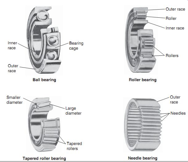
FIG. 3 Different bearings commonly found in power equipment engines and
their components.
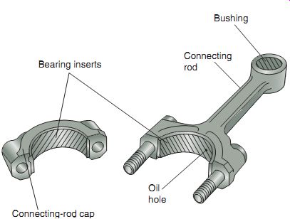
FIG. 4 Plain bearing inserts and bushings can support large radial loads.
In many cases in small power equipment engines, the bearing surface is machined
instead of using an insert bearing.
Plain bearings require constant high oil pres sure to produce a lubricating film known as hydrodynamic lubrication. This oil film, located between the rotating shaft and the bearing, is required at all times during engine operation to prevent unwanted metal-to-metal contact.
The plain bearing receives the majority of its wear during the start phase of engine operation, due to the lack of lubrication at the time of engine start-up.
Bushings
Like plain bearings, the purpose of bushings is to support large radial loads and, occasionally, axial loads. Bushings are cylindrical in design with a lining made of a soft alloy such as brass, aluminum, plastic, or silicone bronze (FIG. 4). Most bushings are press-fit into place and are generally replaceable. A press fit is a force fit that's accomplished using a press.
In contrast, a push fit is a force fit that's accomplished manually.
Seals
Although not used to reduce friction, seals are used on transmission shafts and other rotating shafts within a power equipment engine to Prevent oil loss from the engine and bearings Keep contaminants from entering the engine and bearings
Seal out atmospheric air, when necessary There are many types of seals (FIG. 5). Seals are usually held in place by press or push fit.
In most cases, the seal lip applies tension against the shaft by the use of a spring, which creates a predetermined amount of sealing pressure. The engine oil keeps the seal lubricated for durability.
TWO-STROKE ENGINE LUBRICATION
FIG. 5 Seals are made in different ways to keep oil and lubricants inside the component as well as to keep contamination out of the engine.
As mentioned in Section 6, the lubrication of a two-stroke engine is different from that of a four-stroke engine. In the two-stroke engine, lubrication is accomplished by mixing fuel with a recommended two-stroke oil and then introducing the mixture to the internal moving parts of the engine. When the oil-and-fuel mixture enters the engine, the oil lubricates the piston and other moving parts. The mixture also enters the combustion chamber, where it's ignited by a timed ignition spark. Because the oil doesn't burn as well as the fuel, some of it exits out the exhaust system.
Oils used to lubricate two-stroke engines are specially prepared and recommended by the manufacturer. They help reduce piston-to- cylinder wall scuffing and reduce excessive carbon buildup in the cylinder combustion chamber, exhaust ports, and exhaust systems. It's essential to combine the special two-stroke oil and fuel before the mixture enters the engine, to ensure that all internal engine components receive the correct amount of lubrication. The oil uses the fuel as a carrier to get into the engine and then separates itself from the fuel. Although it does eventually burn to an extent, the oil isn't designed to burn with the fuel in the combustion chamber, but to lubricate the moving parts of the engine.
There are two methods used for two-stroke engine lubrication.
Premixed Fuel and Oil
The premixed method of lubrication in a two stroke engine is by far the most common method found in power-equipment-based engines and requires the use of a specified ratio of gasoline and oil mixed together in a specified container.
It's usually recommended that this procedure be completed in a separate fuel container to ensure proper mixing. FIG. 6 shows that the fuel and oil have already been combined before entering the engine. It's important to always shake the mixture well before using it, to ensure that the oil and gas are completely mixed.
Use the following steps to determine how much oil to mix with the fuel to obtain the proper fuel-to-oil ratio.
Step 1 Divide 128 (the number of ounces in a gallon of gasoline) by the manufacturer's recommended fuel-to-oil ratio.
Step 2 Multiply the result of Step 1 by the number of gallons of gasoline to be used. The result is the number of ounces of oil you need to add to the gas.
As an example, let's determine how much oil must be added to 5 gallons of fuel when the manufacturer recommends a 40:1 fuel-to-oil ratio.
Step 1: Divide 128 by 40. The result is 3.2, which is the number of ounces of oil that must be added to each gallon of fuel.
Step 2: Multiply 3.2 by 5. The result is 16.
Therefore, 16 ounces of oil must be added to 5 gallons of fuel.
The recommended ratio of fuel to oil may vary from 16:1 (16 parts of fuel to every 1 part of oil) to 50:1 (50 parts of fuel to 1 part of oil). Variations are based upon the manufacturer's recommendations and the brand of oil used.
Many brands of oil are available, each with different lubrication qualities. Be sure to investigate each product carefully and choose one based on the manufacturer's recommendations.
More important, choose one that best protects the two-stroke engine's moving parts.
One disadvantage of premixing the fuel and oil is that there's no way to adjust the amount of oil entering the engine with the fuel as the engine operates. At slow engine speeds, the engine doesn't work as hard; thus the proportion of oil may be greater than required to lubricate the engine components. The result may be excessive oil in the engine. As the engine speed is increased, excess oil exits through the combustion chamber, causing exhaust smoke as the mix ture burns. Excessive oil can also cause the spark plug to foul, or misfire. At higher engine speeds, on the other hand, the proportion of oil may not be adequate to supply sufficient lubrication needed to reduce friction. These are reasons why it's so important to use the manufacturers recommended oils and oil ratios.
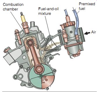
FIG. 6 Using the premixed method of lubrication in a two-stroke engine,
the user combines the fuel and oil manually, before the mixture enters the
engine.
Oil Injection
Although not often found in power equipment engines (but commonly found in other two-stroke machines such as snowmobiles), oil injection systems deserve some discussion here.
The method of injecting oil into the engine, instead of premixing it with the fuel, requires the use of a pump. An oil pump measures and feeds the oil from a separate storage tank to all the two-stroke engine's components that require lubrication. With an oil injection system (FIG. 7), the mixing of oil and gas occurs automatically. Increasing or decreasing the speed of the engine regulates the amount of oil pumped to the engine's components.
Oil injection systems offer several advantages. Not only does the power equipment engine user not have to mix the oil with the gas but also perhaps more important, oil is supplied to the engine's internal components in the correct amount required to provide the best protection at different engine speeds. Most two-stroke engines using oil injection have internal oil pas sages to help feed more oil to those internal engine components that require more lubrication. Examples of such areas are bearings of the connecting rod big end and crankshaft main bearings. A smaller quantity of oil is fed to those engine components requiring less oil. Examples include the piston wrist pin and rings.
Oil injection systems can reduce the total oil consumption of the engine because the oil is used only as needed, on the basis of the engine's operating speed. This helps reduce oil consumption, spark plug fouling, and excessive smoke and can help to increase the engine's life.
More important, oil injection pump systems supply the proper amount of oil to the moving parts, even when the carburetor slide is suddenly closed down and the engine speed remains high.
This prevents engine seizure, which would other wise be caused by lack of lubrication. Remember, with the premixed method, oil must enter the two-stroke engine with the fuel. When the carburetor slide is closed on deceleration, the oil supply to the engine's internal components is drastically reduced. An oil injection system, on the other hand, doesn't have this disadvantage.
In the oil injection system, a cable connecting the throttle housing to the oil pump controls oil pump output (FIG. 8). Turning the throttle up causes the carburetor throttle valve and oil pump to open. This allows the oil pump to automatically increase its oil output in proportion to the air or fuel supply from the carburetor.
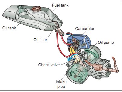
FIG. 7 Although not very common in the power equipment two-stroke engine,
the oil injection method of lubrication allows for the mixing of oil and gas
automatically, assisted by an oil pump that feeds the oil from a storage tank.
Oil injection is found commonly in two-stroke engines of implements such as
snowmobiles.
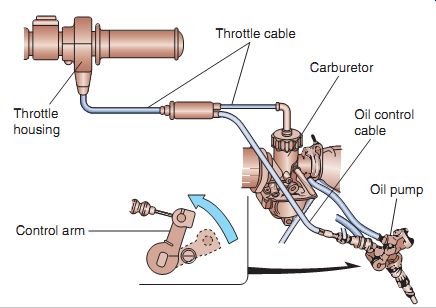
FIG. 8 The throttle cable controls the oil-injected two-stroke engine
oil pump.
Most two-stroke engines synchronize the oil pump to the carburetor throttle valve; that is, the pump is set to supply a quantity of oil to the engine in direct relation to the quantity of air- fuel mixture supplied to the engine. As a general rule, the pump lever to which the cable is connected is adjusted to move to a predetermined point when the throttle is wide open and to return to its original position when the throttle is closed.
Different methods are used to indicate the oil pump lever position in relation to the carburetor throttle valve opening. Usually a punch mark on the throttle valve is aligned with a mark on the carburetor body when the pump lever is in the proper position. This is a common procedure, but you'll need to check the power equipment engine service manual for further instructions on the type of pump design and recommended adjustment.
In oil injection systems, the oil storage tank must not be allowed to run dry. If this happens, or if the oil pump is removed, air enters the oil lines.
Air in the system won't allow the oil to flow properly to the components in need of lubrication. The air must be removed to ensure that proper lubrication takes place. The method used to remove air bubbles from oil lines is called bleeding. This is done by removing the oil line located at the oil pump. After this line is removed, the oil flows out through the hose, bringing the air bubbles along with it. You should allow the oil to drip into an oil pan placed under the pump. How does this really work? The oil storage tank is located physically higher than the oil pump, thereby allowing gravity do the job. When the oil line is removed from the pump, gravity lets the oil flow freely from the oil storage tank. Manufacturers suggest various methods for bleeding a system. You should follow their instructions carefully.
FOUR-STROKE ENGINE LUBRICATION
Unlike the case of the two-stroke engine, the lubrication system for the four-stroke power equipment engine requires the engine oil and gasoline to be kept separate from each other.
Therefore, in the four-stroke engine, the oil isn't mixed with the gasoline, nor does oil enter the combustion chamber. Consequently, oil isn't burned; rather it's recirculated throughout the engine.
Four-stroke engine lubrication systems used in power equipment engines are wet-sump systems, meaning that the engine stores all the available engine oil in the engine's crankcase.
In comparison, a dry-sump engine stores the majority of its oil in a separate storage tank with oil lines going into and from the engine.
Examples of areas needing lubrication are cam bearings, overhead valve rocker arms, push rods, pistons, cylinders, and crankshaft bearings.
Wet-Sump Lubrication
Wet-sump lubrication systems store all the oil in the engine's crankcase. Either oil is pressure-fed to all areas in need of lubrication or a system that splashes the oil to areas that require lubrication. Examples of areas needing lubrication are cam-bearing areas, pistons,
cylinders, and crankshaft-bearing areas. The oil that is fed to these areas is thrown off the rotating components and drained back to the sump, where the oil recirculates to those high-friction areas that need lubrication.
Oil Circulation
Four-stroke power equipment engines use one of two ways to circulate engine oil: splash or pump. There are two basic types of oil pumps used in power equipment engines: the plunger type and the rotor type.
Oil for all lubrication systems is stored at the bottom of the engine, also known as the oil sump. The oil sump is where the engine oil is stored for lubrication purposes and also where the engine oil returns once it has been used. All engine sumps have at least two removable plugs.
The oil drain bolt is located at the bottom of the engine (FIG. 9) and is used to remove the engine oil. The oil filler cap is used to check and fill the crankcase. Sometimes a check bolt is used to verify the correct amount of oil is in the engine (FIG. 10).
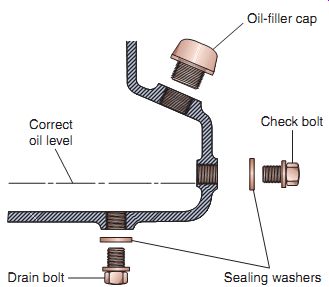
FIG. 9 A check bolt is used to verify that the correct amount of oil is
in the engine.
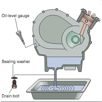
FIG. 10 Typically, a power equipment engine will have an oil drain bolt
as well as an oil filler cap.
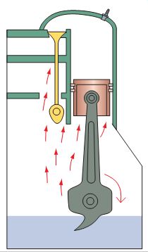
FIG. 11 Splash-type lubrication.
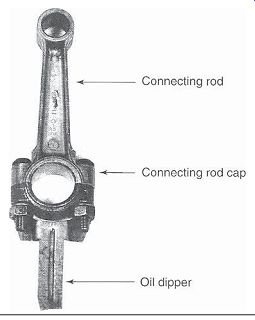
FIG. 12 A connecting rod with an oil dipper attached.
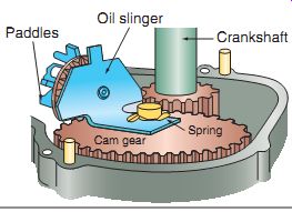
FIG. 13 Oil slingers are often found in vertical engines using splash-type
lubrication.
Splash Lubrication
Many older and less expensive small four stroke engines use a splash lubrication system.
Just as its name implies, the splash lubrication system relies on the splashing of the oil onto engine parts for lubrication.
To splash the oil onto the parts needing lubrication, horizontal engines commonly use an oil dipper (FIG. 11). An oil dipper is a piece attached to the connecting rod (FIG. 12) used to move (splash) the oil from the engine's sump to the engine parts in need of lubrication. The dipper rotates as the connecting rod and crank shaft rotate. In vertical engines, the connecting rod isn't submerged in the oil. Therefore, another method is used to get the oil to the components in need of lubrication.
In vertical crankshaft engines, an oil slinger is used, which consists of a gear with paddles to splash oil on the parts (FIG. 13). The oil slinger gear meshes with the camshaft gear and as the camshaft turns, the slinger turns. The paddles dip into the oil and splash the oil to areas in need.
When the engine is running, oil is splashed upward onto the cylinder and the piston to provide a film of oil between the piston and cylinder wall. In some engines, the oil falls back down and into holes in the connecting rod and crankshaft-bearing surfaces and then runs through return slots back into the engine sump by the force of gravity alone. All the internal engine parts are lubricated in this fashion.
As we mentioned, this type of lubrication system is used in older and inexpensive engines to cut down on costs of manufacturing. The engine's life expectancy isn't as high as we would like.
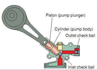
FIG. 14 A plunger-type oil pump. It should be noted that not all plunger
oil pumps use check valves, as shown in this illustration.
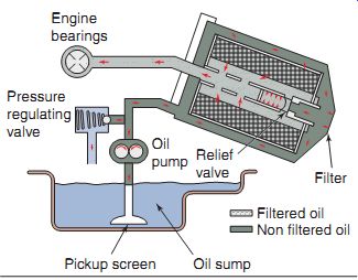
FIG. 15 The main components of a full pressure lubrication system.
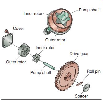
FIG. 16 The rotor-type pump is found commonly in full pressure lubrication
systems.
Pressure Lubrication
Pressure lubrication is a system where a pump pressurizes the oil and forces it through passage ways to the specific engine parts. Pressure lubrication is much better than splash lubrication as the pressurized oil provides a constant film of oil between the parts it is directed to. The constantly moving oil also does a better job of carrying away heat and flushing away dirt from the parts. There are two types of pressure lubrication pump systems found in power equipment engines: the plunger type and rotor type.
Plunger-Type Oil Pumps
The plunger-type oil pump consists of a set of check valves, a piston attached to a plunger, and a pump body or cylinder (FIG. 14). The plunger has a large hole at one end that fits over an eccentric shaft on the camshaft. An eccentric shaft is a shaft that is off center. The pump body is like a cylinder.
When the piston moves up in the oil pump's cylinder, oil is drawn in past the inlet check ball.
As the piston moves back down the cylinder, the inlet check ball closes and oil is forced past the outlet check ball, and pressurized oil is delivered to the engine parts via oil holes and passage ways. The pump is submerged in the oil sump to allow a constant source of oil. The pump body is stationary, whereas the plunger and piston move whenever the engine is rotating.
Rotor-Type Oil Pumps
Higher-quality four stroke power equipment engines use a full pres sure lubrication system. The main components of a full pressure lubrication system are the oil sump, oil pickup screen, oil pump, oil filter, and oil passageways (FIG. 15).
The rotor-type pump (FIG. 16) is used commonly in full pressure lubrication systems.
The rotor pump consists of a pair of rotors: an inner rotor and an outer rotor. The inner rotor is shaft driven, whereas the outer rotor is moved by the inner rotor and is free to turn in the housing. The lobes on the rotors squeeze oil through passages in the pump body. As the inner rotor rotates, oil is constantly picked up from the inlet side, transferred, and pumped through the out let side. Oil pressure is created when the oil is squeezed between the inner and outer rotors.
The rotor-type oil pump design is capable of creating both high volume and high pressure.
Rotor-type pumps are also known as gerotor or trochoidal pumps. Oil pressure must be regulated in a full pressure lubrication system. This is done by the use of an oil pressure relief valve by the means of a spring-loaded valve used to bleed off excessive oil after the oil pressure reaches a predetermined level.
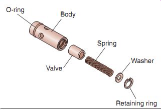
FIG. 17 The components of the oil pressure relief valve.
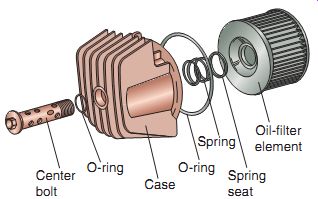
FIG. 18 A paper-style cartridge oil filter, with components that complete
the oil filter assembly.
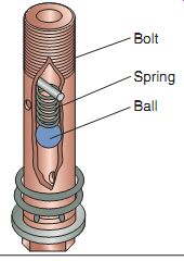
FIG. 19 A typical oil filter bypass valve and its components.
Oil Pressure Relief Valve
The oil pressure relief valve is usually located near or on the oil pump (FIG. 17). Its purpose is to prevent excessive oil pressure from building up by bleeding excessive oil back into the crankcase. The oil pressure relief valve operates during cold starts when the oil is thicker and when the engine is run outside of the designed parameters set by the manufacturer.
Oil Filters
Oil filters are used to ensure that the oil is as clean as possible before it enters the oil passageways and reaches the component parts.
The paper oil filter uses treated-pleated paper; it may be of a spin-on-type or a cartridge-type (FIG. 18). Pleated paper is used to provide a large surface area for filtering purposes. As the oil makes its way through the paper, dirt and acids stick to the outside and only clean oil gets through to the engine. If a filter is left in too long, it can clog and will not allow oil to flow to the engine parts. In such a case, an oil filter bypass valve (see following text) can prevent total engine damage. O-rings are used to seal the filter housing as it attaches to the crankcases and should be lubricated during installation. It's important to note that when oil filters are used, they must be replaced or cleaned on a regular basis.
Oil Filter Bypass Valves
Most spin-on-type oil filters and cartridge type oil filters include an oil filter bypass valve.
When oil flow through the filter is restricted because of an excessively dirty filter or extremely cold running conditions, the oil filter bypass valve allows the oil to bypass the filter, thus pro viding the essential lubrication to critical engine components. Notice that the oil filter bypass valve illustrated in FIG. 19 has a bolt, which contains a spring and a ball. When pressure is excessive in the oil filter housing, the ball pushes the spring, allowing the oil to bypass the filter.
Unfiltered oil is better than no oil at all!
Oil Passages
Oil passages, or pipes, deliver the oil from the pump to the crankshaft, camshaft, valves, and all other internal parts in need of lubrication. Most crankcases have holes machined into them to supply oil to the crankshaft. Some models use an external oil line to deliver oil to the top end.
COOLING SYSTEMS
As we discussed in previous sections, heat energy created within the engine is used to produce power. The heat created in the combustion chamber of a typical engine can reach temperatures as high as 3,600°F (1,982°C)! A significant amount of heat is absorbed by the parts of the engine itself, which can quickly dam age the engine if not removed (dissipated). Of course, the more heat energy that can be used, the more power the engine will produce. This is the tricky part for manufacturers, as they have to determine just how much heat the parts can take before they fail. Power equipment engine cooling systems assist in the removal of excess heat produced by the engine. They're designed to allow the engine to operate at a temperature predetermined by the manufacturer. There are two types of cooling systems found in power equipment engine engines: air cooling and liquid (coolant) cooling.
Air Cooling
Most small power equipment engines are air cooled. Air-cooled engines use cooling fins on the cylinder head and cylinder (FIG. 20) to dissipate heat to the surrounding air. These two areas of the engine get the hottest when the engine runs. Cooling fins are thin pieces of metal cast on the cylinder and cylinder head, used to get the greatest amount of available hot metal in contact with cool air.
As the engine runs and produces heat, it transfers the heat to the cooling fins. Air flows around the fins and carries away the heat. As the heat is pulled from the engine, the heat is reduced (FIG. 21a) to as low as 100°F (38°C). Quite a difference from the high temperatures originally created within the engine! The primary air-cooling method used in power equipment engines is called forced-draft cooling, which uses an engine-driven fan, typically the engines flywheel, which draws air through ductwork, also known as shrouds (FIG. 21b). When a new charge of fuel and air is drawn into an engine, a notable amount of heat is absorbed also.
Shrouds surround the cylinder and the cylinder head. The flywheel has curved blades that are used to pull cool outside air into the engine and push it around the engine parts. The fly wheel fits inside a blower housing, also known as a fan cover, which directs the air into and out of the flywheel to the shrouds. Cool air is pulled into the fan through a debris screen that keeps grass and other foreign material out of the housing, thereby preventing clogging and eventual overheating. If debris does get through the screen, the fans are designed to cut up the debris into smaller pieces to allow it to flow through the cooling system without being caught in the cooling fins.
FIG. 20 This cutaway photo shows the cooling fins found on a typical small power equipment engine.
Liquid Cooling
Although making the engine slightly heavier because of the extra components required, liquid-cooling systems are popular with large power equipment engines being built today. A liquid-cooled engine gives the manufacturer the ability to control better the engine's operating temperature. Liquid-cooled power equipment engines contain various components, including the:
- Water pump
- Radiator
- Thermostat
- Radiator cap
- Coolant Radiator fan
Water Pump
The purpose of the liquid-cooled engine's water pump is to circulate the coolant. The water pump is driven by the engine (FIG. 22). It draws the coolant through the inlet pipe and discharges it into the engine's water jackets. The water pump ensures that the coolant is sent to all needed areas in a uniform manner. The pump consists of a pump shaft, impeller, bearings, mechanical seal, oil seal, and a housing.
The water pump housing includes a drain hole, known as a telltale hole. Coolant leaking out the telltale hole is an indication that the mechanical seal is leaking (FIG. 23). This is the most common problem found in a power equipment engine liquid-cooling system. Some water pumps may be rebuilt, but in most cases, the pump is replaced if the mechanical seal fails.
If engine oil appears to be leaking out through the telltale hole, the oil seal is at fault. The oil seal is generally replaceable and doesn't require replacement of the water pump.
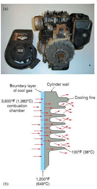
FIG. 21 (a) Heat is transferred from the inside of the engine to the i
ns on an air-cooled engine. (b) The forced-draft method of air cooling uses
an engine-driven cooling fan to push air through the engine shroud and to the
engine's cooling fins.
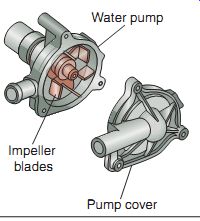
FIG. 22 A typical water pump assembly.
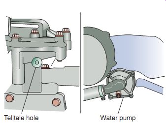
FIG. 23 The telltale hole in a water pump gives a warning (i.e., coolant
leaking out the telltale hole) when the pump needs repair or replacement.
Radiator
The radiator is a cooling device that allows for rapid heat removal. The radiator cools the moving liquid inside the cooling system as it's pumped through the engine. A radiator is also known as a heat exchanger. The radiator consists of small tubes or passages surrounded by very thin cooling fins (FIG. 24). Hoses connect the radiator to the engine, are flexible, and are made of butyl rubber and generally rein forced with steel wire.
In most power equipment engines, the radiator is made of aluminum alloy. If a radiator is damaged, it generally needs to be replaced.
Although it's possible to repair radiators in power equipment engines, the cost to repair them may be higher than the cost to replace them.
Thermostat
The thermostat is a temperature-sensitive flow valve. Its purpose is to provide a quicker engine warm-up time. It also ensures that the engine operates at a predetermined temperature.
When the engine is cold, the thermostat is in the closed position. This allows the coolant to flow through the engine only and not into the radiator. When the engine reaches its predetermined operating temperature, the thermostat opens, permitting the coolant to flow through the radiator (FIG. 25).
The thermostat may be tested by suspending it in heated water and checking the temperature with a thermometer when it opens (FIG. 26). If the thermostat doesn't open at the correct temperature given by the manufacturer, doesn't open at all, or doesn't close, it must be replaced.
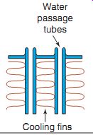
FIG. 24 In a radiator, air flowing past the fins cools the coolant as
it flows through the water passage tubes.
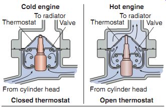
FIG. 25 The thermostat remains closed when the engine is cold, keeping
the flow of coolant from reaching the radiator. This provides for quicker engine
warm-ups. When the engine reaches a predetermined operating temperature, the
thermostat opens, allowing coolant to pass through the radiator.
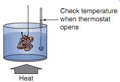
FIG. 26 A thermostat may be tested by suspending it in heated water and
checking the temperature with a thermometer when it opens.
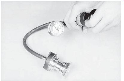
FIG. 27 A cooling system tester can be used to perform a radiator cap
pressure test.
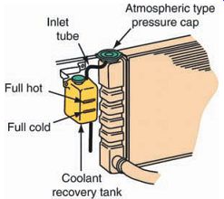
FIG. 28 Most radiators have a coolant recovery tank, which allows for
the expansion of the coolant after the radiator cap opens if pressure gets
too high.
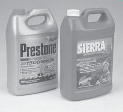
FIG. 29 Different types of engine coolants can be found at most automotive
part stores.
Radiator Cap
The radiator cap seals the cooling system from the outside atmosphere. It's also used to limit the cooling system's operating pressure.
The boiling point of a liquid is increased by 3°F for every 1 pound per square inch (psi). Power equipment engine radiator caps are usually designed to hold 12-17 psi of pressure. They may be tested using a pressure tester (FIG. 27). If the cap fails the test, it must be replaced.
Most radiators have a coolant reservoir, also known as a recovery tank (FIG. 28), which allows for the expansion of the coolant after the radiator cap opens if pressure gets too high. During the pressure relief, coolant flows through a tube next to the radiator cap into the reservoir tank. As the system cools off, the cool ant is drawn back into the radiator by vacuum.
The coolant reservoir tank is normally made of clear plastic and has lines on it that show a full hot and cold line. When checking the system, the coolant should be between these two lines.
Coolant
The coolant for a liquid-cooled power equipment engine (FIG. 29) usually consists of a 50:50 mixture of distilled water and antifreeze (ethylene or propylene glycol). One part water is used for every part of antifreeze because water has much better heat transfer capabilities than pure antifreeze. For the purpose of engine protection, distilled water is better than plain tap water because the former doesn't contain mineral deposits, which can cause corrosion. You must use the type of coolant recommended by the manufacturer to ensure that the engine is protected from damage due to corrosion. You should never use 100% ethylene glycol in any cooling system. Ethylene glycol is a poor cool ant when used alone. The purpose of using anti freeze in a liquid-cooled engine is to lower the freezing point and raise the boiling point of the liquid (water). By mixing antifreeze with water in the proper proportion, antifreeze lowers the freezing point of water to less than 30°F. (Water normally freezes at 32°F.) At the same time, antifreeze and the cooling system pressure raise the boiling point of water to more than 225°F. (Water normally boils at 212°F.) Antifreeze also contains lubricants, antifoaming additives, and corrosion inhibitors that help protect the engine. The antifreeze-and-water coolant is pumped along water jackets through the cylinder head and cylinder. The heated cool ant then flows through the radiator, where heat is dissipated to the surrounding air.
Radiator Fan
The fan used with the liquid-cooled engine system helps to move air through the radiator when the engine isn't in motion or when it's moving too slowly to get the correct amount of air through the radiator. The fan may be driven by a pulley-and-belt arrangement, which turns when ever the engine is running. It may also be made to turn by an electric motor using DC (battery) voltage (FIG. 30) and controlled by a temperature-sensitive sensor. Electric- powered fans are designed to operate only when the engine reaches a predetermined temperature. The fan may be designed to continue running even if the power equipment engine is shut off.
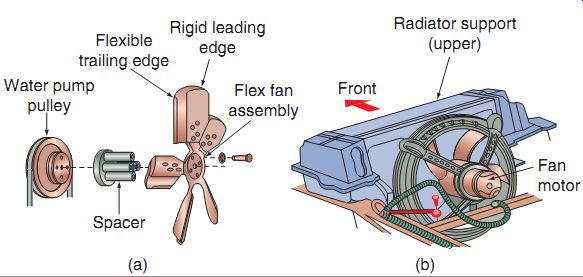
FIG. 30 Cooling fans can be driven by a pulley and belt (a) or they may
be controlled by an electric motor (b).
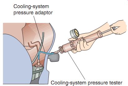
FIG. 31 A cooling system pressure tester can be used to ensure that there
are no leaks in the system.
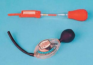
FIG. 32 Two hydrometers are shown here.
Hydrometers are used to measure the specific gravity of a liquid. When antifreeze is added to water, the hydrometer measures the weight change.
Liquid-Cooling System Testing
Liquid-cooled systems can be pressure tested to check for leaks (FIG. 31). Pressure testing verifies that the system can hold a specified pres sure for a required period of time. Specifications for this test are available in the manufacturer's service manual for the specific model. If the sys tem fails the pressure test, check the hoses, pipe connections, the water pump installation, and seals. The radiator cap can also be pressure tested, as mentioned earlier. If the system does not hold pressure after it has been determined that all out side components are working well, there may be an internal leak that will require deeper investigation into areas such as the head gasket.
Another common test for liquid-cooled engines is a specific-gravity test. This test uses a hydrometer, which measures the weight of liquid as compared with the weight of water (FIG. 32). When antifreeze is added to water, the hydrometer measures the weight change.
Another tool used to test specific gravity is a refractometer.
Summary
There are the four key purposes of lubrication: cooling, cleaning, sealing, and lubricating to reduce friction.
There are various types of oils, classified by letter codes and viscosity ratings.
Bearings, bushings, and seals are needed in an engine to reduce friction.
Both two-stroke and four-stroke engine lubrication systems have specific purposes.
There are two different types of lubrication systems used in two-stroke engines and three types of lubrication systems found in four stroke power equipment engines.
Most power equipment engines are air cooled but can also be liquid cooled to prevent over-heating.
QUIZ
1. Name four purposes of oil lubrication.
2. is the term used to refer to the thickness of oil.
3. The abbreviation API stands for _____.
4. The abbreviation SAE stands for ____.
5. What special type of lubricant is manufactured in gel form?
6. Oil that has the letter "W" after its number rating indicates that it was tested at temperature.
7. When premixing a two-stroke engine's gasoline and oil, what does the ratio 50:1 represent?
8. Using the steps described in this section, what's the correct amount of oil to premix with 5 gallons of gasoline using a 20:1 fuel-to-oil ratio?
9. The type of air-cooled engine that uses an engine-driven fan and shrouds is called a system.
10. The component used as a heat exchanger in a liquid-cooled engine is called the ___.