AMAZON multi-meters discounts AMAZON oscilloscope discounts
Goals:
- Understand the general and scientific terms and laws associated with power equipment engines
- Describe the operation of a basic internal combustion engine
- Explain how fuel and air are used to make an engine operate
- Identify the component parts used in a four-stroke engine
- Describe the theory of operation for a four-stroke engine
- Identify the component parts used in a two-stroke engine
- Explain the theory behind the operation of a two-stroke engine
- Understand the different induction systems used in the two-stroke engine
- Describe how a two-stroke engine physically differs from a four-stroke engine
- Understand the advantages and disadvantages of the two-stroke engine and four-stroke engine used in the power equipment engine
-------------
INTRODUCTION
In Section 5, we learned about the various power equipment engine configurations. Now we'll focus on how power equipment engines operate. We'll begin by discussing physical laws that pertain to engines. Then we'll describe the theory of operation for a basic internal-combustion engine.
After you understand basic engine operation, we'll focus on the four-stroke engine. We'll discuss the basic components used in a four-stroke engine and then take an in-depth look at how a four-stroke engine operates. We'll then look at the two-stroke engine. We'll identify the components found in the two-stroke engine and learn how the two-stroke engine operates. We'll then describe the different types of induction systems. After completing our discussion of the two-stroke engine, we'll discuss the differences between two-stroke engines and four-stroke engines. Finally, we'll look at the advantages and disadvantages of each of these engine designs.
GENERAL AND SCIENTIFIC TERMS AND LAWS
Before we go into detail on how engines operate, it's important to understand terms and principles related to the combustion process and gasoline engines.
Matter
Matter can be described as any substance that occupies space and has weight. Matter can't be created or destroyed but can be changed from one form to another by a chemical or physical process. An example of matter changing from one form to another is a block of ice. The ice turns to water if not kept at a freezing tempera ture. Also, if enough heat is applied, the water can be changed to steam.
Matter can be in the form of a solid, liquid, or gas. The block of ice in the example is considered to be solid matter because it has three dimensions (length, width, and depth) that can be measured. When the ice melts, it changes from a solid form into a liquid form (water). A liquid has no definite shape and conforms to the shape of the container holding it. A liquid has the ability to exert pressure but can't be com pressed. Another interesting fact about a liquid is that it won't burn! That's right, liquids don't burn. The following are two terms describing liquids that relate to engine operation.
An atomized liquid consists of liquid drops suspended in air. An example of an atomized liquid is an early morning fog. Because an atomized liquid is still a liquid, it won't burn.
A vaporized liquid is a liquid that's converted to a gaseous state through a heating process.
A vaporized liquid has the ability to burn.
Vaporized liquids are used to make an engine run.
Steam is a gas or gaseous matter. Keep in mind that we aren't talking about gasoline when we talk about gas. Gasoline is a liquid. A gas has no definite shape and, like a liquid, conforms to the shape of its container. A gas can transmit pressure but is lighter than a liquid when com pared in equal volumes. Unlike a liquid, a gas is highly compressible.
An excellent example of a gas is the air we breathe. Air is made up of approximately 78% nitrogen, 21% oxygen, and 1% inert or inactive gases. The oxygen in the air keeps us alive and also helps an engine run at its best.
Air density can be described as the amount of oxygen per given volume of space, or in other words, the thickness of air. The air all around us is actually compressed. At sea level, air pressure is 14.7 pounds per square inch (psi). Air density decreases as altitude increases or when the temperature rises. When air density decreases, there are fewer oxygen molecules in the air. It would be more difficult for you to work at the same level of intensity at 10,000 feet above sea level than at 1,000 feet above sea level. Likewise, it's also more difficult to work at the same level of intensity on a very hot and humid day than on a cool and dry day. The same changes affect how an engine runs! As air density decreases, there are fewer oxygen molecules in the air for you and your engine to breathe!
Viscosity A liquid will flow through a path such as a water hose. Its path of flow affects how fast a liquid flows. For example, a liquid won't flow uphill without some sort of pressure acting on it. The temperature of a liquid also affects its ability to flow. As the temperature of a liquid increases, the liquid tends to get thinner. This change is known as viscosity. Viscosity is a mea sure of a liquid's resistance to flow. You'll generally see the word viscosity in the context of oils used in engines. A liquid with high viscosity offers greater resistance to flow as compared with one with low viscosity.
Boyle's Law
As we stated earlier, a gas, like air, can be compressed. There's a physical law governing the interplay between pressure, volume, and temperature. This law, known as Boyle's law, states that the pressure and the volume of a given mass of gas remains constant if its temperature is not changed. Boyle's law tells us that when a gas is compressed, its temperature and pressure increase. The more a gas is compressed, the higher its temperature and pressure. Each time you decrease the volume of a gas one half, you double the pressure it exerts.
Pressure Differences
Pressure differences result in movement of a gas from a high-pressure area to a low-pressure area, in the process moving any matter that may be in the way along with it. A gas at high pres sure always seeks low pressure. A common example of pressure differences can be seen every day in the weather around us. In engines, carburetion and the intake or induction phase take advantage of pressure differences for operation.
We generally call pressure differences vacuum when talking about engines.
Momentum Velocity is the speed of an object in a given direction. Mass is the weight of any form of matter. Momentum is the driving force that's the result of motion or movement. Momentum is determined by multiplying mass (weight) times velocity:
Momentum 5 Mass 3 Velocity
Laws of Motion
Two laws of motion concerned with under standing engine operation are the law of inertia and the law of action and reaction. The law of inertia states that anything at rest or in motion tends to remain at rest or in motion
until acted upon by an outside force. The law of action and reaction states that for every action there's an equal and opposite reaction. These laws of motion were introduced by Sir Isaac Newton.
Energy
Energy is the ability to do work. If we have lots of energy, we can do lots of work. Energy itself can't be seen; however, the results of energy can be seen. An example is lifting a box and set ting it on a table. Only the physical movement of the box can be seen. Energy exists in many forms and can be changed from one form to another. For example, a battery changes chemical energy to electrical energy. However, conversion of energy from one form to another is never 100% efficient. An example is your heating sys tem at home. As your heating system burns fuel, most of the heat is used to warm your home; however, some of the heat is lost up the chimney.
The same is true in a power equipment engine. Burning fuel in the engine provides the energy to move the power equipment engine, but some energy is lost in friction and heat produced by the engine.
There are two types of energy:
Potential energy. Energy that is stored, as in a charged battery or a can of gasoline.
Active energy (or kinetic energy). Energy that is in use or in motion, as when a battery is used to light a lamp or when gasoline is used to run an engine.
THE BASIC INTERNAL COMBUSTION PROCESS
In Section 5, we discussed the basic components and operation of an engine. Now we'll discuss these topics again but in greater detail.
Power equipment engines use a principle called combustion to operate. Combustion is the rapid combining of oxygen molecules with other elements. When elements are combined with oxygen, the ensuing chemical changes can result in the release of heat. Heat usually speeds up any chemical change and can act as a catalyst. A catalyst is generally a substance that speeds up a chemical reaction without under going any change itself. A cold condition usually slows down most chemical changes. This is why engines tend to run better when warmed up than when they're first started.
The engines found in all modern power equipment units are internal combustion engines. In an internal combustion engine, compressed fuel and air are burned inside the engine to produce power. The internal combustion engine produces mechanical energy by burning fuel. In a power equipment engine, fuel is sent to the engine through an induction system, where it's burned inside to produce the power that's used to help make the engine run. In contrast, an external combustion engine burns fuel outside of the engine.
A steam engine with a boiler is an example of an external combustion engine. We won't discuss the external combustion engine design here because it's not relevant to power equipment engines.
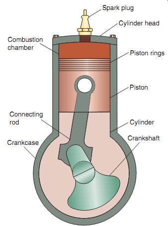
FIG. 1 A simplified cutaway view of an engine. During operation, the piston
moves up and down inside the cylinder. This movement is transferred to the
crankshaft through the connecting rod.
Construction of the Internal Combustion Engine
Let's begin by reviewing some of the common parts in any type of internal combustion engine (FIG. 1). The cylinder is a hollow metal tube. The top end of the cylinder is sealed by the cylinder head, which is bolted onto the top of the cylinder. The piston, which is the main moving part in an engine, is a can-shaped metal component that can move up and down inside the cylinder.
The area between the piston and the cylinder head is called the combustion chamber. In this chamber, a mixture of air and gasoline is compressed and burned to produce power.
A spark plug is screwed into a threaded hole in the cylinder head. The end of the spark plug protrudes from the cylinder head and into the combustion chamber. The spark plug is used to ignite the compressed air-fuel mixture in the cylinder and cause it to burn. The sparking action of the spark plug is controlled by the engine's ignition system, which we'll discuss in detail in Section 15.
When the air-fuel mixture burns correctly in the combustion chamber, the gases inside expand rapidly. The expansion of the gases due to the rapid burning is enough to force the piston downward the cylinder. The bottom end of the piston is attached to a connecting rod and crankshaft assembly. When the piston is forced downward the cylinder, the downward motion is transferred to the rod and crankshaft. The rod and crankshaft then convert the up-and down (or reciprocating) motion of the piston into circular or rotary motion.
Now, let's take a few minutes to review a few terms that were presented earlier. When a piston is at its highest position in the cylinder, it's said to be at top-dead center (TDC) (FIG. 2). When the piston is at its lowest position in the cylinder, it's said to be at bottom-dead center (BDC). The distance that the piston moves from the top of the cylinder to the bottom of the cylinder is called the piston stroke.
The outside surface of a piston has several horizontal grooves cut into it. Each groove holds a metal ring called a piston ring. A piston ring is a metal ring that's split at one point and is de signed to be springy. The piston rings slip over the outside of the piston and fit into the piston ring grooves. Once they're in place, the rings stick out like ridges on the surface of the piston. When a piston is inside a cylinder, the piston rings press outward against the walls of the cylinder. This helps form a tight seal between the piston and the cylinder, which is necessary for proper engine operation.
The Three Phases of Internal Combustion
There are two methods of initiating normal combustion in an engine. The first method is ignition, which happens when an atomized fuel makes contact with a spark. The second method comprises reducing the space occupied by oxygen and a combustible material, which produces heat. Power equipment engines use a combination of these two methods. The air-fuel mixture is compressed into a very small space. An ignition spark begins the combustion process. As the air-fuel mixture burns, the hot expanding gases push the piston down. The combustion process changes potential energy in the form of the air-gas mixture (chemical energy) to active (kinetic) energy in the form of heat. There are three phases of combustion that occur during the power stroke of the internal combustion engine: combustion lag, active combustion, and post combustion.
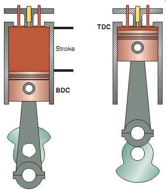
FIG. 2 An engine with the piston located at top-dead center (right) and
bottom-dead center (left).
Combustion Lag
The first phase of the internal combustion engine process starts as the piston moves upward and compresses the air-fuel mixture.
The spark plug ignites a small portion of this mixture before the piston reaches TDC. A ball of fire spreads outward and begins to consume the remaining compressed air-fuel mixture. However, this ball of fire that initiates combustion doesn't immediately spread outward. A chain reaction soon occurs, as a result of which the gases expand rapidly. Before the chain re action spreads to the outside area of the combustion chamber, a short period of relatively slow burning takes place. This slow burning is known as combustion lag.
Active Combustion
The second phase of the internal combustion engine process begins when the initial combustion lag is overcome and the chain reaction begins to spread quickly outward. A rapid temperature and pressure buildup occurs as the charge is consumed. The chain reaction of burning molecules accelerates and the chemical conversion causes heat to be released very quickly. This increase in temperature causes the pressure in the cylinder to increase. This phase is known as active combustion.
Post Combustion
As the piston moves down and the volume inside the cylinder increases, the pressure drops and the power is then absorbed by the piston.
The cylinder now eliminates spent gases to prepare for the next cycle of fresh air-fuel mix ture. All engines begin to release exhaust gases out of the cylinder well before the piston reaches BDC. This phase is known as post combustion.
Results of Combustion--The heat and power generated within the combustion chamber produce work, which is realized through the crankshaft and eventually through the drive system of the power equipment unit.
Although most four-stroke engines run at lower temperatures, cylinder head temperatures can be as high as 300-375°Fahrenheit (°F). Combustion chamber gas temperatures within the engine are known to be as high as 4,000°F. This relates to cylinder pressures reaching 800-1000 psi. The heat produced expands the gases in the combustion chamber and pushes the piston toward BDC.
The chemical changes that occur during combustion convert the fuel-air mixture into the following chemicals:
Carbon monoxide (CO). Results from partially burned fuel or fuel that's not completely burned during the combustion process.
Remember that carbon monoxide is a color less, odorless, poisonous, and deadly gas.
Hydrocarbons (HC). Results from unburned or raw fuel.
Carbon dioxide (CO2). The result of complete combustion.
Oxides of nitrogen (NOx). Forms of oxidized nitrogen resulting from extremely high combustion temperatures.
Water (H2O). Results from complete combustion. Believe it or not, for every gallon of fuel burned, approximately 1 gallon of water is produced in a vaporized form.
In the United States, the Environmental Protection Agency (EPA) has developed emission standards for new non-road engines. Since 1995, power equipment engines have been required to comply with EPA emission standards. The two key emissions produced by power equipments and monitored by the EPA are hydrocarbons and oxides of nitrogen.
INTERNAL COMBUSTION ENGINE OPERATION
So far, we've looked at the basic internal combustion process in a typical engine. Now, let's take a look at how combustion is used to enable the engine to operate. In order to work, all internal combustion engines must perform four basic actions. They must:
Take in air and fuel
Squeeze or compress the air-fuel mixture
Ignite and burn the mixture
Get rid of the burned gases
These engine actions are the four events of engine operation. You may recall that the proper names for these events are intake, compression, power, and exhaust. When an engine is operating, it continually runs through these four events, over and over again.
Intake. Air that has been mixed with fuel is drawn into the cylinder because of the downward movement of the piston, which increases cylinder volume and lowers the pressure in the cylinder, in effect creating a vacuum.
Compression. The piston rises and com presses the air-fuel mixture trapped inside the combustion chamber.
Power. The air-fuel mixture is ignited. The rapid and confined burning of the fuel pushes the piston back down the cylinder.
The downward motion of the piston is transferred through the connecting rod to the crankshaft.
Exhaust. The exhaust gases are released from the cylinder. The four events then begin all over again.
One engine cycle is a complete run through of all four events of operation: intake, compression, power, and exhaust. Keep in mind that the four events of operation we've described occur very quickly, and they repeat continually for as long as the engine is running. All power equipment engines operate in these same four basic events, and all the events must occur in order for the engine to run properly. To understand how an engine works, one of the most important things you can do is memorize the four events of engine operation. Once you understand these four events, everything else we discuss about engine operation will fall into place.
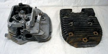
FIG. 3 There are two basic types of cylinder heads in power equipment
engines. The cylinder head on the left contains the intake and exhaust valve
train components. The cylinder head on the right is more or less a cover for
the cylinder, which caps the top of the engine.
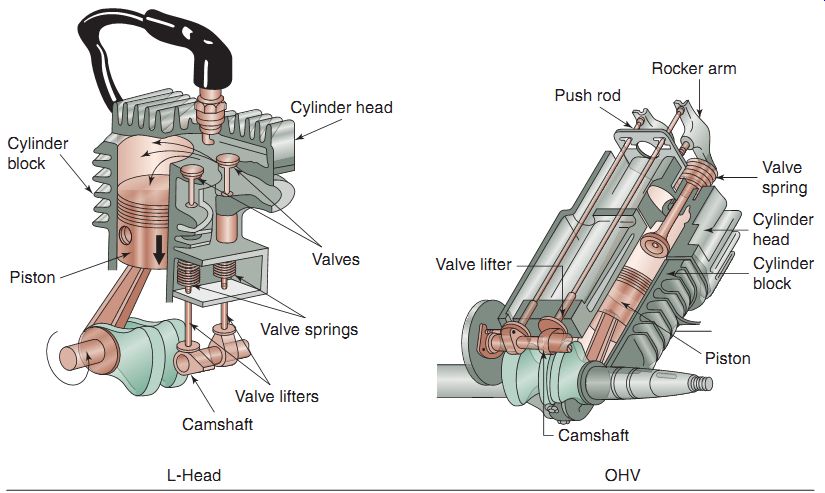
FIG. 4 An L-head-type engine (left) and overhead valve (OHV) engine (right).
Note that the valves are contained in the block on the L-head-type, whereas
they're attached to the head on the OHV head.
BASIC FOUR-STROKE ENGINE COMPONENTS
Now that we've reviewed the basics of engine operation, let's look at the four-stroke power equipment engine components in more detail.
We'll cover all the basic parts of a four-stroke engine and explain their purpose. Many components found in four-stroke engines are in
two-stroke engines also. Refer to the illustrations for reference as we discuss each component. Be aware that not all engines look exactly alike. However, the illustrations provided are typical of four-stroke engines you'll see.
Four-Stroke Cylinder Heads
Cylinder heads are constructed out of aluminum alloy or cast iron (FIG. 3). There are two basic types of cylinder heads found in power equipment engines. One, known as an L-head-type, is more or less a cover for the cylinder, which caps the top of the engine. The other type of four-stroke cylinder head, called the overhead valve (OHV) cylinder head, holds the intake and exhaust valve train components. All cylinder heads seal the top end of the cylinder for compression of the air-fuel mixture under the spark plug (which is threaded into the cylinder head) to increase combustion efficiency.
Holes in the OHV cylinder head are called ports and provide for the air-fuel mixture to come into the combustion chamber and also remove the spent gases after the combustion process. Cylinder heads also aid in the transfer of heat from the engine by the use of fins in air-cooled engines or by using water jackets in liquid-cooled engines.
Most power equipment engines use one valve each for the intake and exhaust (2-valve systems) but may have more valves for each cylinder. The intake valve area, in most cases, is larger than the exhaust valve area in the four-stroke engine. This is because it's more difficult to get the intake gases into the engine than it is to remove the gases that are being pushed out of the exhaust valve.
There are two basic types of valve mechanisms found in power equipment engines: L-head and OHV (FIG. 4). The L-head-type uses a valve design that has the valves located in the cylinder block next to the piston. Commonly called a flathead or side-valve, the L-head type of engine was popular in many older power equipment engines and is still used in some engines. The OHV-type uses a valve design that locates the valves in the cylinder head above the piston. Use of the OHV is becoming popular because this style of engine is much more efficient at getting the gases get in and out of the combustion chamber. The result of this design is increased power and less emissions.
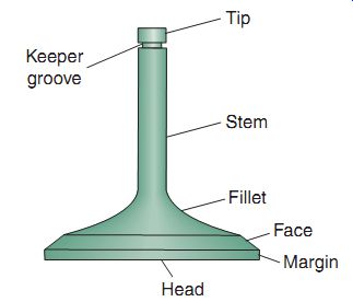
FIG. 5 Parts of a typical poppet valve.
Poppet Valves
Four-stroke engines use mechanical valves called poppet valves to control the gases coming into and going out of the engine. Poppet valves, which are tulip shaped, open and close every other crankshaft revolution. The poppet valve may be made from stainless steel, carbon steel, or titanium. The intake valve allows the air-fuel mix ture into the cylinder. The following list describes various parts of a poppet valve (FIG. 5):
The keeper groove is where keepers lock the valve and spring retainer in place.
The valve fillet is the sloped area of the valve that connects the valve stem to the valve head.
The valve face mates with the cylinder head valve seat to seal gases in the combustion chamber and aid in heat transfer. The valve face is often coated with stellite to reduce wear and prolong the life of the valve.
The margin supports the valve face and shields the face from high combustion temperatures.
The valve head is the bottom portion of the valve and forms a part of the combustion chamber.
The valve tip is the part of the valve that rides against the valve-opening device. Most valve tips are stellite plated for wear. Stellite is an extremely hard metal alloy that resists wear and won't soften at high temperatures.
The valve stem is the thrust surface for the valve guide and is considered to be a major wear area. If the stem is worn, excessive amounts of oil can pass between the stem and guide into the combustion chamber.
If oil leaks into the combustion chamber, smoke appears in the exhaust.
Common wear areas of the valve are the tip, face, stem, and keeper groove.
Valve Seats
Cylinder head valve seats (FIG. 6) are stationary in the cylinder head or cylinder block depending on the engine design and are the sealing surface for the valve face. When servicing valve seats, there are generally three angles cut into the valve seat to allow for optimum air and fuel flow into the cylinder through the valve opening.
Valve Guides
Valve guides (FIG. 6) are installed in the four-stroke cylinder head or in the cylinder block depending on the engine type. Valve guides pro vide a bushing surface for the valve stem.
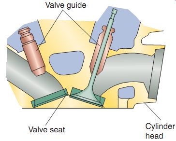
FIG. 6 Valve seats and guides are located in the cylinder head on the
OHV engine. On the L-head-type, seats and guides are located in the block but
they perform the same function.
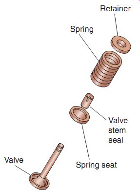
FIG. 7 A valve spring and the components used commonly to close the valve.
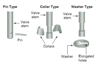
FIG. 8 Three types of retaining methods used in power equipment engines.
The collar-type and washer-type retainers are the most popular.
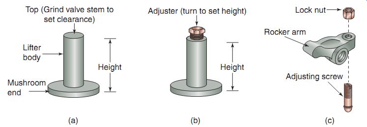
FIG. 9 A valve clearance with a screw and lock nut for adjustment (c)
and two types of valve lifters (a and b). The lifter on the center is adjusted
with its own adjuster, whereas the lifter on the left requires grinding of
the valve. Valve clearance is important to allow for heat expansion, oil clearance,
and proper sealing of the valve.
Valve Stem Seals
Valve stem seals are installed on the valve guides and are used to prevent excessive oil from entering between the inside of the valve guide and valve stem. Depending on the engine design, valve seals may be installed on the intake, exhaust, or both valve guides.
Valve-Closing Devices
Valve-closing devices keep the valve closed when required. The most common method to close a valve is with the use of coil springs (FIG. 7) attached between the valve and the cylinder head or block depending on the type of engine.
The springs are held in place with valve spring retainers and valve keepers that fit into the valve keeper grooves. Although many modern four stroke power equipment engines use only one valve spring, some use two coil springs per valve to reduce the chance of valve float. Valve float is a condition in which the valve doesn't stay in constant contact with the valve train. Valve float can occur when the valve springs are weak or during excessively high engine speeds.
Valve springs are held in place by retainers (FIG. 8). There are three types of retainers found in power equipment engines: pin-type retainers are found in older engines, whereas collar-type and washer-type retainers are more commonly found in today's engines.
Valve-Opening Devices
There are two common types of valve-opening devices used in the four-stroke power equipment engine depending on the type of engine being used: rocker arms and valve lifters. They can be reviewed using FIG. 4.
The rocker arm is a lever that can gain a mechanical advantage and change the direction of force applied to it. There are various rocker arm designs used in the four-stroke engine but they all perform the same function. Rocker arms are found in OHV engines.
The valve lifter, also commonly called tappet, is used to directly open the valve from under the valve. This type of valve-opening device is seen in L-head engines.
Valve Clearance
Valve clearance or lash is necessary to allow for heat expansion, oil clearance, and for proper sealing of the valve. Too little clearance causes improper sealing of the valve and excessive heat.
Too much clearance causes excessive noise.
There are different ways (FIG. 9) used to adjust valves in power equipment engines.
The screw and lock nut uses a screw that can be turned in or out to change the clearance.
After the adjustment has been made, a lock nut holds the screw in place. The screw and lock nut may be located on the rocker arm, on a push rod, or on a valve lifter.
Some valves are adjusted by removing them and grinding the tip. You must be careful not to grind off too much of the valve; so use caution when adjusting the valve using this method.
Four-Stroke Camshafts
The purpose of the camshaft (also known as the cam) is to change rotary motion to reciprocating motion. The camshaft is also a mechanical valve timer that controls:
When to open
How fast to open
How far to open
How long to stay open
When to close
How fast to close
How long to stay closed
Parts of a Camshaft
The various parts of a camshaft are important to its ability to function properly in the four stroke power equipment engine (FIG. 10).
The base circle is the area of the camshaft that forms a constant radius from the center line of the journal to the heel. The heel is the part of the camshaft that allows the valve to seat onto the cylinder head and seal off the combustion chamber.
Clearance ramps take up the valve clearance and open and close the valve. These ramps act similarly to a shock absorber and are used to gently (relatively speaking!) open and close the valve.
The flanks of the camshaft determine and control the acceleration of the opening and closing of the valve.
The nose is the area of the camshaft where the valve is opened the greatest distance from the cylinder head area; it controls lift dwell. Lift dwell is the amount of time in crankshaft degrees that the valve stays open at maximum lift.
Camshaft lift is a measure of the difference between the base circle and the nose.
Depending on the type of engine, this may or may not translate into the actual valve lift, which is the distance that the valve actually moves away from the cylinder head.
The duration of a camshaft is a measure of how long the valve is held open. Duration is measured in crankshaft degrees.
Most camshafts have what's known as valve overlap built into them. Valve overlap occurs between the exhaust and intake strokes. It's the time for which both valves are open simultaneously and is measured in crankshaft degrees. High performance engines generally have more valve overlap to allow for more air-fuel mixture to be packed into the cylinder combustion chamber. As high velocity exhaust gases leave the cylinder, a low pressure area is created. Opening the intake valve allows fuel and air to be drawn into the cylinder quicker. Although this allows for higher peak power, an engine with a camshaft exceeding 30° of valve overlap will lack efficiency in the low- and mid-range power areas of the engine.
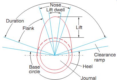
FIG. 10 The parts of a camshaft.
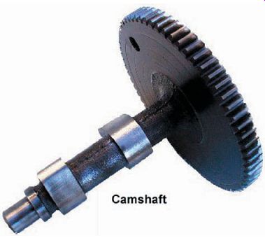
FIG. 11 A typical camshaft.
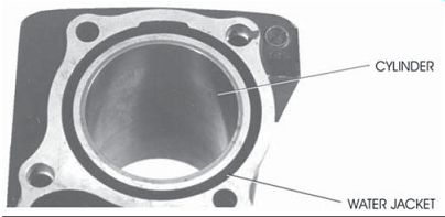
FIG. 12 A typical liquid-cooled cylinder.
A liquid-cooled cylinder uses water jackets as opposed to the cylinder i ns used in an air cooled cylinder.
Camshaft Drive
The camshaft rotates at one-half the speed of the crankshaft to properly time the intake and exhaust valves with the piston as it moves up and down the cylinder. The primary method used to drive the camshaft is by a gear attached to the camshaft, which is driven by the crank shaft (FIG. 11). The gear on the camshaft has twice as many gear teeth as found on the crankshaft drive gear, to allow for the one-half speed factor mentioned. The gears of the crank shaft and camshaft operate in an oil bath in the crankcase.
Four-Stroke Cylinders
The purpose of the four-stroke engine cylinder is to guide the piston as it travels up and down.
The cylinder is attached directly to the crankcase in most cases in the typical power equipment engine and helps to transfer engine heat. These cylinders may be either air cooled or liquid cooled.
Liquid-cooled cylinders have water jackets surrounding the cylinder area (FIG. 12).
There are different types of materials used in the construction of a cylinder. Each material has its advantages and disadvantages.
Cast-iron cylinders. These can be fit with oversized pistons by boring to a larger size.
When a cylinder is bored, material is re moved from the cylinder to enlarge the hole.
A larger oversized piston (and appropriate piston rings) is then used in place of the previous piston. The cast-iron cylinder is inexpensive to manufacture but has poor heat transfer characteristics when compared with other materials used to construct cylinders. Not found often in today's modern power equipment engines, cast-iron cylinders are very heavy.
Aluminum cylinders with cast-iron or steel sleeves. These have much better heat transfer abilities than cast-iron cylinders and are much lighter. These cylinders can also be bored to a larger diameter. In some cases, the sleeve can also be replaced if needed, but in most cases, the cost to replace the cylinders is less than that to replace the sleeve. This type of cylinder is most popular in today's engines and allows for longevity of the engine.
Aluminum cylinders. Cylinders made of aluminum have the least weight and when properly maintained, last a long time. The disadvantage of aluminum cylinders is that although they can be bored when needed, it's prohibitively costly to do so. They're generally replaced when damaged. These cylinders are the least expensive to produce.
Plated aluminum cylinders. These use a thin layer of chrome or Nikasil to increase the durability of the cylinder. This combines the lightweight benefit of aluminum with added durability of a hardened cylinder surface.
Some cylinders may have tiny scratches cut into them called crosshatches. Crosshatching is accomplished by honing the cylinder wall with a tool called a cylinder hone. The purpose of honing is to help seat the piston rings and retain a thin layer of oil on the cylinder walls to keep them properly lubricated.
Cylinders must be round from top to bottom to work properly. They shouldn't have any taper or out-of-roundness. We'll discuss how to mea sure four-stroke cylinders later, in Section 12.
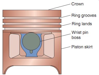
FIG. 13 The parts of a typical four-stroke piston.
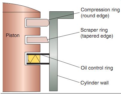
FIG. 14 Three common types of piston rings found in four-stroke engine
pistons.
Four-Stroke Pistons
The purpose of the piston is to transfer power produced in the combustion chamber to the connecting rod. The piston is manufactured in a way that makes it directional. This makes it necessary to install the piston in the specific manner indicated in the service manual.
Pistons are tapered from top to bottom. The top of the piston is smaller than the bottom to allow for different heat expansion rates of the piston. To allow for further heat expansion, pistons are cam ground so they're oval in shape when cold. When the piston reaches operating temperature, it becomes round to match the cylinder.
There are two common piston-manufacturing methods: cast aluminum and forged. Cast-aluminum pistons are the more common.
Forged pistons use aluminum alloy forced into a die under extreme pressures. This manufacturing method produces a stronger piston, but makes the piston more expensive.
A piston has several parts (FIG. 13). The crown is the top of the piston and acts as the bottom of the combustion chamber. The crown is the hottest part of the piston, because of the high combustion chamber temperatures. The crown area expands more than the rest of the piston because it's hotter and has more mass.
The piston crown may have a positive dome, flattop, or negative dome. There also may be machined clearance notches in the crown to allow for valve relief.
The ring grooves allow for installation of piston rings. The bottom ring groove of the four stroke piston has holes or slots for oil return that help remove oil from the cylinder wall. This also helps to lubricate the wrist pin. The piston ring lands support the piston rings.
The wrist pin boss is where the piston attaches to the small end of the connecting rod. A hardened tool-steel wrist pin attaches the piston to the rod. The wrist pin is generally held in place with retaining clips to prevent it from contacting the cylinder wall.
The piston skirt is the load-bearing surface of the piston. The piston skirt contacts the cylinder wall and is the primary wiping surface for the cylinder wall. The largest diameter of the piston is usually at or close to the bottom of the skirt and 90° from the wrist pin. This is where the piston is generally measured.
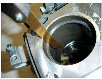
FIG. 15 The piston ring end gap is measured using a feeler gauge. Ring
end gap is required to allow for heat expansion.
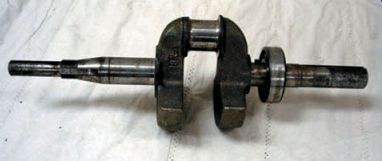
FIG. 16 A one-piece crankshaft used in four-stroke engines.
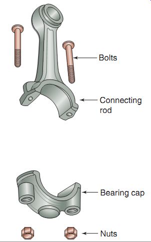
FIG. 17 The typical connecting rod on a power equipment engine is a multipiece
design, as illustrated here. The rod may or may not have nuts on the end (instead
it may have threads).
Four-Stroke Piston Rings
The purpose of piston rings is to aid in heat transfer from the piston to the cylinder wall, seal in the combustion gases, and prevent excessive oil consumption. Generally, there are three types of piston rings used on the four-stroke piston (FIG. 14):
The compression ring. This ring is closest to the piston crown and is used to seal most of the combustion chamber gases. The compression ring is usually made of cast iron and may be chrome plated or Tel on or moly coated.
The scraper ring. This is the middle ring and aids in sealing the combustion chamber gases. The scraper ring scrapes excessive oil from the cylinder wall. Like the compression ring, the scraper ring is made of cast iron but in most cases has no coating. Many modern engines no longer use the scraper ring. This is to reduce friction and increase the engine's horsepower rating.
The oil control ring. This is the ring closest to the piston skirt. The oil control ring removes the oil from the cylinder walls left behind by the piston skirt.
Piston rings have an end gap to allow for heat expansion. The ring end gap is measured by using a feeler gauge after fitting the ring squarely in the cylinder (FIG. 15). Ring end gap should be measured at the locations recommended by the engine manufacturer.
Four-Stroke Crankshafts
As we discussed earlier, the purpose of a crankshaft is to change the reciprocating motion of the piston into a rotary motion. The primary parts of a crankshaft include journals and counterweights (FIG. 16). The main journals support the mass of the crankshaft and are located at the center of the rotating axis and supported by bearings, bushings, or a combination of both. A connecting-rod journal supports the connecting rod and is offset from the main journals. Counterweights add momentum to the crankshaft. The counterweights assist in keeping the crankshaft rotating and the engine running smoothly by counterbalancing the reciprocating masses from the piston and connecting rod. Some engines use remote counter balancers, which are located on separate shafts and are chain or gear driven. Counter-balancers must be timed properly with the crankshaft.
Four-Stroke Connecting Rods--The connecting rod is a lever that transfers power from the piston to the crankshaft. Connecting rods in power equipment engines are usually made of aluminum but can also be made of steel. Both types generally use an I-beam construction to increase strength.
The typical connecting rod is of a multi piece (FIG. 17) design and consists of the connecting rod, connecting-rod end cap, and connecting-rod bolts. The multipiece connecting rod is precisely machined on each end to allow for a smooth bearing surface.
Four-Stroke Crankcase
The purpose of the crankcase is to house and support the major engine components, which include the crankshaft, cylinder, and camshaft.
The four-stroke crankcase must be vented to the atmosphere to prevent excessive pressure from building up inside the engine. The most common type of crankcase found in power equipment engines is the one-piece design. A one-piece crankcase consists of a case that's a single-piece construction with a separate access cover to remove main components (FIG. 18). Also known as a "block," this type of crankcase is the most common crankcase found in power equipment engines.
FIG. 18 A cutaway of a one-piece engine crankcase (also known as a block).
All the components of the engine are contained in or on the block.
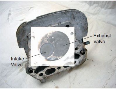
FIG. 19 The intake valve (on left) is almost always larger than the exhaust
valve.
THEORY OF OPERATION OF THE FOUR-STROKE ENGINE
Although the four-stroke engine is somewhat complex in design because of the parts necessary for it to function, it's relatively simple in terms of operation. The engine runs by repeatedly completing a cycle of operation. Each cycle of operation consists of two crankshaft revolutions in which four piston strokes occur. Each of the four piston strokes performs a distinct operation.
The four operations (or events)-intake, compression, power, and exhaust-must occur in the proper order for the engine to run correctly.
Valve Operation--As mentioned earlier, the four-stroke engine uses mechanical valves: the intake valve and the exhaust valve (FIG. 19). These valves move up and down to open and close during engine operation. The intake valve opens to allow the air-fuel mixture to flow into the combustion chamber.
The exhaust valve opens to allow exhaust gases to flow out of the combustion chamber after the air-fuel mixture is burned.
The intake and exhaust valves are mechanically lifted to make them open and close. A valve-lifting device that rests on the lobes of the camshaft opens the valves. As the camshaft turns, the lobes open the valves in a timed sequence to match up properly with the up-and-down motion of the piston. The valve springs hold the valves closed when they aren't being forced open by the camshaft and lifting device.
Fuel Induction
To burn properly in an engine, fuel must be mixed with air. This is done via a carburetor or a fuel injection system, generally known as a fuel induction system. Fuel moves from the fuel tank into the induction system, where it's atomized and mixed with air. The air-fuel mixture is then transferred out of the induction system and into the cylinder through the intake valve, where it's vaporized. We'll discuss the specific functions and details of induction systems in Section 8.
The Strokes of a Four-Stroke Engine
Now, let's take a closer look at the individual operations, known as strokes, that occur in the four-stroke engine (FIG. 20).
The Intake Stroke
During the intake stroke, the air-fuel mixture enters the cylinder. The intake sequence starts when the intake valve begins to open. As the piston moves downward in the cylinder away from the cylinder head, the volume of the cylinder above the piston expands. This increase in volume creates a low-pressure area, which develops a less than-atmospheric pressure inside the cylinder.
With the intake valve open, a path is completed through the intake manifold and carburetor.
In an effort to balance the pressure difference between the atmospheric pressure of the outside air and the less-than-atmospheric pressure inside the cylinder, the outside air moves through the carburetor toward the cylinder. (Remember, gas in a high-pressure area will always seek a low pressure area.) The intake valve closes and seals the combustion chamber when the piston is near the bottom of its stroke near the crankshaft.
The Compression Stroke
When the piston approaches BDC, both valves are closed. The air-fuel mixture is now trapped inside the sealed combustion chamber.
At this point, the piston begins to rise, which compresses the air-fuel mixture very tightly in the combustion chamber. This is known as the compression stroke.
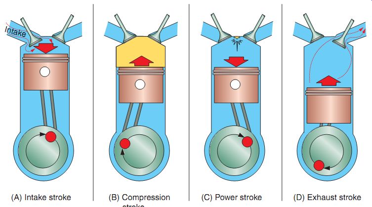
FIG. 20 The four piston strokes of a four-stroke engine in the sequence
needed to complete one cycle of operation. An engine runs by repeatedly completing
this cycle.
The Power Stroke
Just before the piston reaches TDC during the compression stroke, the engine's ignition system fires the spark plug; that is, the ignition system produces an electric current that causes a spark to jump across the two electrodes of the spark plug. When the spark is applied to the compressed air-fuel mixture, ignition causes a rapid contained burn and the compressed air- fuel mixture quickly expands.
When gases burn, they expand rapidly. The force of this contained burn pushes the piston down in the cylinder. The connecting rod, which connects the piston and the crankshaft, causes the downward motion of the piston to force the crankshaft to rotate. This is known as the power stroke.
The Exhaust Stroke
As the piston moves downward during the power stroke, the exhaust valve opens. By the time the piston reaches BDC, the exhaust valve is completely open. As the piston moves up again, it pushes the burned gases out through the exhaust valve. This is known as the exhaust stroke.
Once the exhaust event is completed, the four events of operation begin again. The movement of the camshaft closes the exhaust valve and opens the intake valve, and the piston moves down to begin a new intake event.
The four events of operation continue as long as the engine is operating. Keep in mind that these cycles are repeated at a very high speed.
An average power equipment engine crankshaft rotates anywhere from 500 to 10,000 revolutions every minute. This means that these engine cycles are repeated thousands of times over and over again.
TWO-STROKE ENGINES
We'll now describe the components found in the two-stroke engine. We'll discuss the operation of the two-stroke engine as well as the different types of induction systems (the way that the air-fuel mixture passes through the engine) found in a two-stroke engine.
You've already learned that an engine is classified according to the number of strokes its piston takes to complete one full engine cycle. You've also learned that, for any engine to operate, it must run through four events of operation: intake, compression, power, and exhaust. The four-stroke engine accomplishes these four events in four piston strokes-one stroke for each event. Now we'll learn how the two-stroke engine operates.
As you're aware, in a two-stroke engine, the piston takes only two strokes to complete one full operational cycle. When the piston in a two-stroke engine moves in an upward direction, it completes the intake and compression events.
When the piston moves downward, it completes the power and the exhaust events.
Two-stroke engines are much simpler in design than four-stroke engines. The basic two stroke engine has only three moving parts: the piston, the connecting rod, and the crankshaft.
Note that in the two-stroke engine, there's no camshaft to operate valves for the flow of the air-fuel mixture or exhaust gases.
TWO-STROKE ENGINE COMPONENTS
Before you learn how two-stroke engines operate, we'll discuss the component parts used in two-stroke engines. You'll notice that many of the parts used in the two-stroke engine are similar-if not identical-to those used in the four-stroke engine.
As we've mentioned before, not all engines look exactly the same. The engines illustrated here are typical of many of the two-stroke engines you'll see.
Two-Stroke Engine Cylinder Heads
There are no ports (and therefore no valves) in the two-stroke cylinder head. The purpose of the two-stroke cylinder head is to create a combustion chamber by sealing the area between the cylinder and the cylinder head (FIG. 21). The second purpose is to hold the spark plug. The squish area of the combustion chamber forces the air-fuel mixture into a tight pocket under the spark plug to increase the combustion efficiency. This squish area, or the squish band, is more critical in the two-stroke engine as compared with the four stroke engine.
The modern two-stroke cylinder head is constructed of aluminum alloy. Like four-stroke cylinder heads, two-stroke cylinder heads also aid in the transfer of heat from the engine by the use of fins in air-cooled engines or water jackets in liquid-cooled engines.
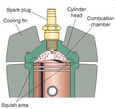
FIG. 21 The two-stroke cylinder head attaches to the cylinder just as
on a four-stroke engine. Note the squish area, which forces the air-fuel mixture
into a tight pocket under the spark plug to increase the combustion efficiency.
This squish area is more critical in the two-stroke engine as compared with
the four stroke engine.
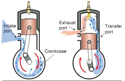
FIG. 22 Ports are located on the cylinder wall of the two-stroke engine.
Two-Stroke Cylinders
The main difference between the two-stroke cylinder and the four-stroke cylinder is that the two-stroke cylinder has holes located in the cylinder wall called ports (FIG. 22). These ports serve the same purpose as the ports in the cylinder head (or block depending on the engine type) of the four-stroke engine.
Ports allow the air-fuel mixture to enter the cylinder and exhaust gases to leave the cylinder and are opened and closed by the piston.
The ports in a two-stroke cylinder may be bridged. Bridged ports are used on very wide ports to prevent the piston ring from catching on the edge of the port. Both the upper and lower edges of the ports are chamfered. When ports are chamfered, the sharp edge of the port is removed to help keep the piston ring from catching as it moves up and down in the cylinder. The ports that may be found in the two stroke cylinder are:
The exhaust port, which is used to allow the exhaust gases to escape.
The transfer ports, which are used to transfer the intake gases from the crankcases to the combustion chamber.
The intake port, which is used to allow the gases to enter the crankcase.
Like the four-stroke cylinder, the two stroke engine cylinder guides the piston as it travels up and down. The cylinder also aids in transferring engine heat and may be either air cooled or liquid cooled. Also, just as with the four-stroke engine cylinder, there are different types of materials used in the construction of a two-stroke cylinder. Each material has its own advantages and disadvantages. You may wish to review the section on four-stroke cylinders in this section for a refresher on the different materials and their advantages and disadvantages.
It should be noted that many small two stroke engines have the cylinder and head attached together.
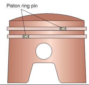
FIG. 23 Pins installed in the two-stroke piston prevent the piston rings
from rotating.
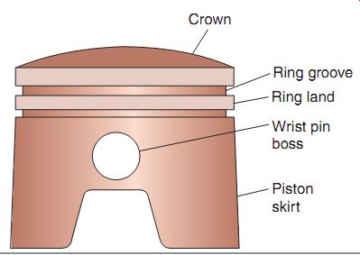
FIG. 24 The parts of a typical two-stroke piston.
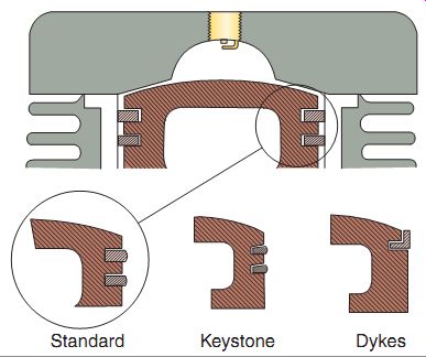
FIG. 25 The three common types of two stroke piston rings.
Two-Stroke Pistons
Just as with the four-stroke piston, the purpose of the two-stroke piston is to transfer the power produced in the combustion chamber to the connecting rod. The two-stroke piston has pins to prevent the piston rings from rotating around the piston and being caught in the cylinder ports (FIG. 23).
The two-stroke piston is similar in design from the four-stroke piston (see FIG. 24).
The crown, which acts as the bottom of the combustion chamber, is the top of the piston.
The crown is the hottest part of the piston, because of high combustion chamber temperatures. The crown area, as in the four-stroke engine, expands more than the rest of the piston because it's hotter and has more mass.
The piston crown on the two-stroke engine generally has a positive dome, but may have a flat top or even a negative dome or dish. The piston crown on a two-stroke engine also controls the duration of the exhaust and transfer ports. Duration is the time that the ports are open and is measured in crankshaft degrees.
Ring grooves have pins installed in them to prevent the piston rings from rotating. The two-stroke piston generally has no more than two piston ring grooves. Piston ring lands sup port the piston rings.
The wrist pin boss is where the piston attaches to the small end of the connecting rod.
A hardened tool-steel wrist pin attaches the piston to the rod. The wrist pin is generally held in place with retaining clips to prevent the wrist pin from contacting the cylinder wall.
The piston skirt is the load-bearing surface of the piston. The piston skirt contacts the cylinder wall and is the primary wiping surface for the cylinder wall. The largest diameter of the piston is usually at or close to the bottom of the skirt, 90° from the wrist pin. This is where the piston is generally measured.
Two-Stroke Piston Rings
The purpose of the two-stroke piston ring is to aid in heat transfer from the piston to the cylinder wall and to seal in the combustion gases.
There are three different types of piston rings used on the two-stroke piston (FIG. 25).
The standard piston ring is rectangular in shape and is the most popular ring found on the two-stroke engine. Standard rings are usually made of cast iron and are chrome plated.
The keystone piston ring is a wedged-shaped ring that seals better than the standard piston ring. However, the keystone ring is more expensive to manufacture and requires a special wedge-shaped piston groove.
The Dykes piston ring is an L-shaped ring that's used only as a top ring on the piston. This type of piston ring expands outward when the combustion gases force the piston downward.
Although the Dykes ring is the most expensive piston ring to produce, it's also the best-sealing ring found on a two-stroke piston.
All piston rings must have an end gap to allow for heat expansion. As we had discussed with the four-stroke piston ring, the piston ring end gap is measured using a feeler gauge (blade) after fitting the ring squarely in the cylinder.
In the two-stroke engine, the ring end gap fits around the piston pin that prevents the ring from rotating around the piston.
Two-Stroke Crankshafts
The two-stroke engine generally uses a multipiece crankshaft (FIG. 26). The crankshaft halves are cast or forged. The connecting rod journal is a pin (crankpin) that's press fit into the crankshaft halves. A one-piece connecting rod uses a roller bearing at the connecting-rod journal. The multipiece crankshaft generally uses ball bearings on the main journals. Most multipiece crankshafts found on a two-stroke engine can be rebuilt.
Two-Stroke Engine Connecting Rods
The connecting rod (FIG. 26) is a lever that transfers power from the piston to the crankshaft. Connecting rods are usually made of stamped steel, forged steel, or aluminum. Some use an I-beam construction for added strength.
The connecting rods found on two-stroke engines are a one-piece design. This design uses a roller bearing at the big end and a needle bearing at the small end of the rod. The one-piece connecting rod generally has holes or slots on both the small and large ends for added lubrication.
Two-Stroke Engine Crankcases
The purpose of the two-stroke crankcase is the same as that of the four-stroke crankcase-to house and support the major engine components.
These components include the crankshaft and cylinder. Unlike the four-stroke engine, which requires ventilation, the two-stroke crankcase must be sealed from the atmosphere to create pressure and vacuum pulses. The two-stroke engine crankcase is usually multipiece and can be horizontally or vertically split. In many two stroke engines, the cylinder is separate from the crankcase instead of being part of the block, as in four-stroke engines. Crankcase seals are used in this design to allow pressure to be held inside the crankcase when the piston moves up and down.
THEORY OF OPERATION OF THE TWO-STROKE ENGINE
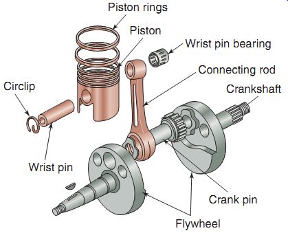
FIG. 26 The parts of a two-stroke engine crankshaft.
Although a two-stroke engine has many of the same components as a four-stroke engine, its method of operation is different. You'll remember that in a four-stroke engine, one power stroke occurs every two revolutions of the crankshaft. In a two-stroke engine, one power stroke occurs for each crankshaft revolution. Two-stroke engines are much simpler in design than four-stroke engines. The basic two stroke engine has only three moving parts: the piston, the connecting rod, and the crankshaft.
The two-stroke engine, though simpler in construction, is more complex in its operation.
The moving parts in all engines must be lubricated with oil to prevent wear. Although we'll discuss the lubrication systems used in two stroke engines in Section 7, it should be noted that the two-stroke engine mixes the oil used for lubrication of the engine components with the fuel supply.
The Four Events of Two-Stroke Engine Operation
Remember, the two-stroke engine must go through the same four events of engine operation as any internal combustion engine-intake, compression, power, and exhaust. However, where the four-stroke engine uses one piston stroke to accomplish each event, the two-stroke engine uses just one piston stroke to accomplish two events (FIG. 27). Each time the piston moves upward, it completes the intake and compression events. Each time the piston moves downward, it completes the power and exhaust events. Because two events of engine operation occur for each piston stroke, the operation of the two-stroke engine is more complex when compared to that of the four-stroke engine.
Two-Stroke Engine Areas
The two-stroke engine is split into two different areas (FIG. 28):
The primary area is the area below the piston crown, including the crankcase. The crank case in a two-stroke engine must be sealed to allow for the compression of the intake gases while they're in the primary area.
The secondary area is the area above the piston crown, including the combustion chamber, where the air-fuel mixture is com pressed to prepare for ignition.
FIG. 27 In a two-stroke engine, as the piston moves upward, it completes the intake and compression stages of operation. As the piston moves downward, it completes the power and exhaust stages of operation.
Two-Stroke Engine Ports
Two-stroke engines don't use the same mechanical valves in the combustion chamber as four-stroke engines do. Instead, the two-stroke engine has holes in the cylinder walls called ports (FIG. 29). These ports control the flow of the air-fuel mixture and exhaust gases. As the piston moves up and down in the cylinder, it covers and uncovers these ports, allowing the air-fuel mixture to enter while also allowing the removal of the exhaust gases.
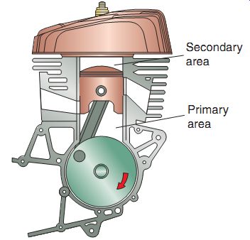
FIG. 28 The area below the piston is called the primary area (crankcase).
The area above the piston is called the secondary area (cylinder).
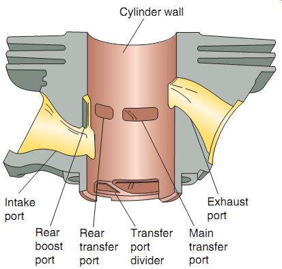
FIG. 29 This cutaway view of a two-stroke cylinder shows its ports.
Two-stroke engines have different types of ports to allow for the flow of intake and exhaust gases.
The intake port is used to control the flow of fresh air and fuel into the primary area (crank case area). Depending on the induction system used, the intake port either is the lowest port in the cylinder or is in the crankcase.
The boost port isn't used on all two-stroke cylinders. It's found primarily on two-stroke engines using reed valves. When boost ports are used, there may be one or more that are located at the rear of the cylinder, opposite the exhaust port. The purpose of a boost port is to allow an extra amount of the air-fuel mixture to flow into the combustion chamber directly from the intake port area. This directly bypasses the crankcase and transfer ports to help fill the secondary area with additional fresh air and fuel to produce more power.
The transfer ports are used to control the transfer of the air-fuel mixture from the primary (crankcase) area to the secondary (cylinder) area.
The transfer inlet is located at the bottom of the cylinder where it meets the crankcase assembly.
The transfer outlet is located in the middle of the cylinder, attached to the crankcase through a transfer tube, which is cast into the cylinder.
The transfer ports are controlled by the position of the piston crown. The number of transfer ports varies from engine to engine. When more than two transfer ports are used, the extra ports are called auxiliary ports.
The exhaust port controls the flow of the exhaust gases from the cylinder. The exhaust port is the highest port in the cylinder. The opening and closing of the exhaust port is con trolled by the position of the piston crown.
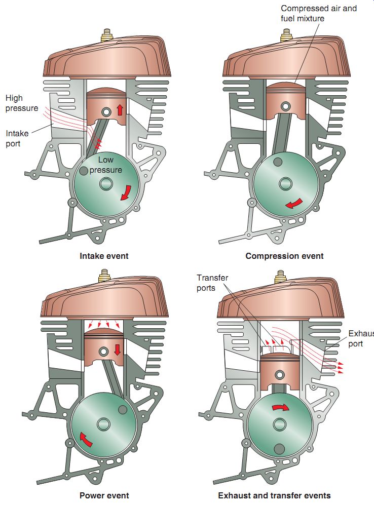
FIG. 30 The five events that occur in one crankshaft revolution in a two-stroke
engine.
Two-Stroke Engine Events
There are five actual events that occur in each engine cycle of a two-stroke engine (FIG. 30). To complete all five events, it takes only two strokes of the piston, which is one revolution of the crankshaft.
The intake event begins when the piston moves toward TDC. The primary (crankcase) area, located below the piston, increases in size, which causes pressure to decrease. Because of the pressure difference, fresh air and fuel are pushed into the primary area through the intake port. The intake event has the longest port duration of all of the two-stroke events.
The compression event (also known as secondary compression) occurs as the secondary (cylinder) area decreases above the piston. The air-fuel mixture that was previously brought
into the cylinder is compressed while the piston is still moving toward TDC. At a precise time, the ignition fires and creates a spark at the spark plug.
The power event begins after the piston reaches TDC, when the expanding combustion gases caused by the ignition force the piston downward. The power event ends when the exhaust port is uncovered (opened) by the piston.
The exhaust event begins when the piston crown uncovers the exhaust port while moving down toward BDC. Because of the high pres sure in the cylinder, the exhaust gases are pushed into the exhaust system.
The transfer event also occurs as the piston is moving toward BDC. As the piston travels down ward, the primary area decreases, which increases the primary-area pressure. This is known as primary compression in a two-stroke engine. While this occurs in the primary area, the secondary area pressure decreases. Because of the pressure differences between the primary and secondary areas, the fresh air-gas mixture located in the primary area is pushed through the transfer ports into the secondary area. The transfer event occurs during the exhaust event, which helps scavenge (similar to four-stroke valve overlap) residual exhaust gases by pushing the remaining exhaust gases out through the exhaust port. The transfer event has the shortest port duration. The transfer event uses what's known as loop scavenging, in which the transfer ports are angled away from the exhaust ports. The angle of the transfer ports directs the fresh air-fuel mixture up and away from the exhaust port to prevent the mix ture from directly flowing out of the port.
TWO-STROKE ENGINE
INDUCTION SYSTEMS
As we've discussed, the intake air-fuel mix ture flows through ports inside the engine.
Two-stroke engines use different methods of controlling the intake flow by what's known as induction. Induction is the method used to pass the air-fuel mixture through the intake port of the engine. Two-stroke power equipment engines use three types of induction systems.
Piston Port Induction--The piston port engine is the oldest and simplest type of two-stroke engine. This engine contains all three engine ports (intake, transfer, and exhaust) in the cylinder walls. As the piston moves up and down, it covers or uncovers the ports.
The piston skirt opens and closes the intake port. As with all two-stroke engines, the piston port engine has a sealed crankcase. As the piston moves upward, low pressure is created in the crankcase. The intake port is uncovered and the air-fuel mixture is drawn into the crankcase.
As the piston continues to move up the cylinder, the exhaust and transfer ports are covered and the air-fuel mixture that's already in the combustion chamber is compressed.
When the piston approaches TDC, the spark plug fires and ignites the air-fuel mixture in the combustion chamber. Once the piston reaches TDC, it's forced downward by the expanding gases and the exhaust gases flow out the exhaust port. As the piston moves downward, the air- fuel mixture in the crankcase is compressed. The transfer port is still closed at this time. As the piston continues downward, the piston uncovers the transfer port. When the transfer port is uncovered, the air-fuel mixture moves from the crankcase area, through the transfer port, and into cylinder.
As the air-fuel mixture enters the combustion chamber area, it helps to remove the remaining exhaust gases. When the piston starts to rise, the intake and compression events begin again.
The piston port engine has the narrowest power band of all two-stroke engines. It may be tuned to run at low speed or high speed, but not both. If the piston port engine is tuned to run at high speed but is operated at low speed, the carburetor tends to allow fuel to come back out of the carburetor. This is called spit back.
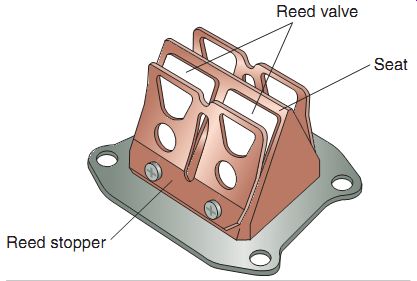
FIG. 31 A typical reed valve assembly.
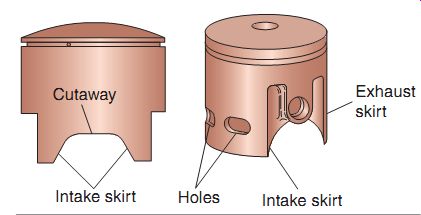
FIG. 32 Two types of reed valve pistons. The piston on the left uses a
cutaway on the intake side of the piston skirt. The piston on the right has
holes on the intake side of the piston skirt.
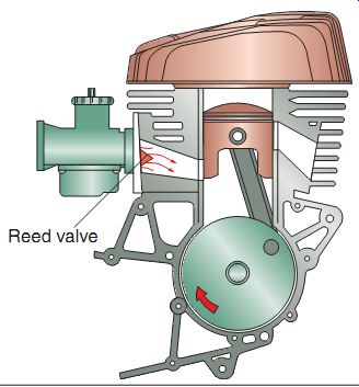
FIG. 33 The location of the reed valve in a cylinder reed valve induction
system in an air cooled two-stroke engine.
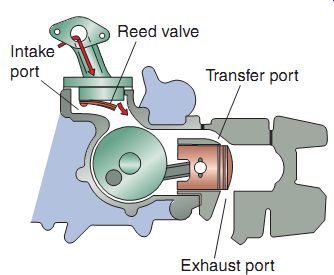
FIG. 34 The location of the reed valve in a crankcase reed valve induction
system.
Reed Valve Induction
To aid in keeping the crankcase sealed and prevent a loss of pressure as the piston moves downward, many modern two-stroke power equipment engines use small one-way valves called reed valves (FIG. 31). A reed valve opens during the intake-and-compression event and then closes tightly during the power-and-exhaust event, to seal the crankcase area and pre vent any of the fuel mixture from escaping back into the carburetor. This prevents spit back.
A reed valve is placed generally between the carburetor and the intake port of the engine. As the piston moves upward during the intake-and compression event of operation, the air-fuel mixture is pulled through the reed valve into the crankcase. When the piston reaches TDC, the reed valve closes, to prevent the air-fuel mixture from flowing back through the carburetor. In this way, the air-fuel mixture is com pressed more completely in the crankcase, which allows the mixture to be pushed more forcefully into the combustion chamber as the piston reaches BDC. Reed valves are made from one of two materials: stainless steel or fiber resin material (fiberglass or carbon fiber).
In some engines that use reed valves, the piston may have either a cutaway or holes on the intake side of the piston skirt to allow the flow of the intake mixture at all possible times (FIG. 32).
Common Reed Valve Induction Systems
There are three types of reed valve induction systems commonly used in two-stroke power equipment engines.
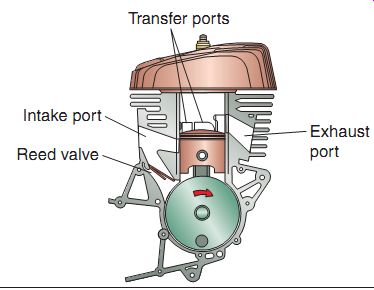
FIG. 35 The location of the reed valve in a piston port/crankcase reed
induction system.
In some older and larger two-stroke engines, the cylinder reed valve induction design (FIG. 33) has the intake port in the same location as the piston port engine (located in the cylinder). With a cylinder reed valve engine, the intake port never closes. The purpose of the cylinder reed valve engine is to broaden the power band of the standard piston port engine.
By using reed valves on a piston port engine, we can tune the engine to run at high speed while the valve prevents spit back through the carburetor at lower speeds.
The crankcase reed valve induction system (FIG. 34) has the intake port located directly on the crankcase. This design can develop a wide power band because it allows a shorter and more direct path to the crankcase and permits approximately 33% more transfer port area.
This lets more air and fuel enter the combustion chamber.
The piston port/crankcase reed induction sys tem (FIG. 35) takes the benefits of both the piston port type of induction to control the lower-speed range of the engine and the crankcase reed induction system for high-speed operation.
FIG. 35 The location of the reed valve in a piston port/crankcase reed
induction system.
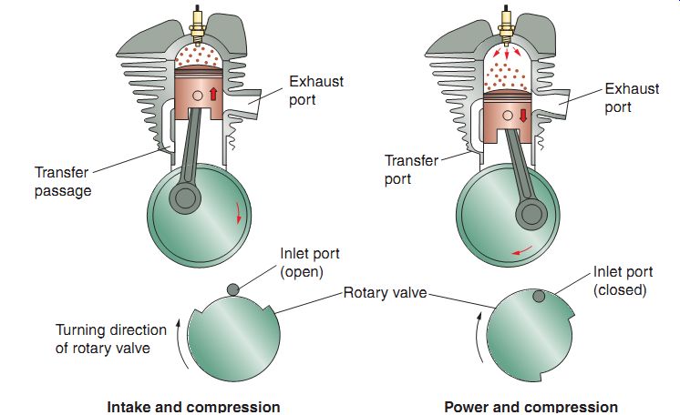
FIG. 36 A rotary-valve induction system in a two-stroke engine.
Rotary Valve Induction
The rotary valve induction system has the intake port located on the crankcase of the engine (FIG. 36). A rotary disk that covers and uncovers the intake port controls the opening and closing of the port. The disk is attached directly to the crankshaft. When the cutaway opening on the disk aligns with the intake port, fuel flows into the crankcase. In a rotary valve assembly, the rotary plate rotates between two fixed plates or between a fixed plate and the crankcase. The two fixed plates, or fixed plate and crankcase, also contain openings. Fuel enters the crankcase only when all three holes line up during the rotation of the rotary plate. At all other times, the rotary valve blocks the passage from the carburetor to the crankcase.
The rotary valve engine design is seldom used in today's power equipment engines because of its size. Rotary valve engines have carburetors attached to the crankcase near the crank shaft and each cylinder has its own disk, which requires that the engine be wider than engines of other designs. This engine generally has the widest power band because it has the shortest and most direct intake path into the primary area of the crankcase.
TWO-STROKE EXHAUST SYSTEMS
The two-stroke exhaust system is a tuned chamber that operates from sonic (sound) waves created by the engine. The shape of the chamber has a direct effect on the performance of the two-stroke engine's operational characteristics. The shape of the expansion chamber also aids in the scavenging of residual exhaust gases and allows for an adjustment of the power band characteristics of the engine.
COMPARING TWO-STROKE AND FOUR-STROKE ENGINES
There are many advantages and disadvantages of two-stroke and four-stroke engines. Because each engine is specifically designed to produce good power over a broad range of engine speeds, you would think that manufacturers would tend to make only one type of engine or the other.
Power equipment engine manufacturers are constantly working to build better, longer-lasting, and more powerful engines.
So, which engine is better-the two-stroke engine or the four-stroke engine? Let's look at the two-stroke engine and compare it with the four-stroke engine.
Advantages of the Two-Stroke Engine
The most noticeable advantage of the two stroke engine over the four-stroke engine is that the two-stroke engine has fewer internal moving parts. This allows the two-stroke engine to be smaller and lighter than the four-stroke engine.
In almost all cases, the two-stroke engine will be lighter than the four-stroke engine when com paring equal displacement engines.
Another advantage of the two-stroke engine is that it generally produces more horsepower compared with a four-stroke engine of equal size. This is because the two-stroke engine has twice as many power strokes in the same given period of time as the four-stroke engine, resulting in better mechanical efficiency.
With these advantages, why aren't all power equipment engine made of two-stroke engines? To answer that question, let's look at the disadvantages of the two-stroke engine.
Disadvantages of the Two-Stroke Engine
The primary disadvantage of the two stroke engine is that it emits a large amount of
hydrocarbons (unburned fuels) in the exhaust, making it a high air-polluting engine. This occurs during the transfer and exhaust events of operation. While the intake gases are being transferred from the primary area to the secondary area of the engine, some of the raw, unburned fuel mixture escapes directly out the exhaust system and into the atmosphere. Even with a properly tuned exhaust system, some raw fuel escapes from the exhaust port at certain engine speeds.
Other disadvantages of the two-stroke engine are directly related to one of its primary advantages. Because the two-stroke engine creates a power stroke every time the crankshaft makes one revolution, it burns more fuel than the four-stroke engine in the same time period.
This generally results in poorer fuel economy.
The two-stroke engine also runs at hotter temperatures compared with four-stroke engines for this same reason. Because the two-stroke engine runs hotter, it's internal parts wear out sooner than those of the four-stroke engine.
This tends to make the two-stroke engine less reliable. It therefore requires more frequent service than the four-stroke power equipment engines.
Finally, as we had mentioned earlier, the basic two-stroke engine has a narrow power band when compared with the four-stroke engine's generally wide power delivery over a range of speeds. For these reasons, most power equipment engine manufacturers primarily build four-stroke engines.
Comparison Tables
Table 1 summarizes our discussion of the advantages and disadvantages of the two-stroke engine compared with the four-stroke engine.

Table 1 Advantages and disadvantages of the two-stroke engine

Table 2 compares the advantages and disadvantages of the four-stroke engine
compared with the two-stroke engine.
Table 2 Advantages and disadvantages of the four-stroke engine
Summary
There are certain physical laws associated with power equipment engines.
All internal combustion engines run using the same basic operational methods.
A mixture of fuel and air is used to make an engine operate.
There are four piston strokes that must be in sequence to complete one full cycle in a four stroke engine.
Many components used in a two-stroke engine are similar to the components found in a four-stroke engine.
Although simple in construction, the operation of the two-stroke engine is somewhat complex.
There are different types of induction systems used in the two-stroke engine.
A two-stroke engine has various differences compared with a four-stroke engine.
There are advantages and disadvantages with both a two-stroke engine and four-stroke engine used in the modern power equipment.
QUIZ
1. If you travel from sea level to 10,000 feet above sea level, what happens to the density of the air?
2. If a gas is compressed, what happens to its temperature?
3. What type of liquid has the ability to burn?
4. What are the four events of engine operation?
5. What type of combustion engine is found in all modern-day power equipment engines?
6. The camshaft in a four-stroke engine rotates at the speed of the crankshaft.
7. The one-piece connecting rod is used on multipiece crankshafts. (True/False)
8. In a four-stroke engine, if the piston is rising toward TDC and valves are closed, the engine is on the stroke.
9. Hot gases are released from the four-stroke engine during the stroke.
10. The cylinder used in a two-stroke engine contains to allow for the flow of gases through the engine.
11. The three basic moving parts in a two stroke engine are the , the , and the .
12. The opens and closes the ports in a two-stroke engine.
13. Two-stroke engines generally generate more hydrocarbon emissions than four-stroke engines. (True/False)
14. Two-stroke engines are heavier than four stroke engines. (True/False)