AMAZON multi-meters discounts AMAZON oscilloscope discounts
Goals:
- Learn about reciprocating engines
- Understand the basic differences between a two-stroke engine and a four-stroke engine
- Understand how engines are rated
- Distinguish the primary components found in a two-stroke engine and a four stroke engine
- Learn about the different cooling systems used in power equipment engines
- Understand the different engine configurations found in power equipment engines
-----------------
BASIC ENGINE OPERATION
In this section, we'll look at the different power equipment engine designs and configurations. We'll start with a simple overview of how engines work in general and then move to a basic overview of the different types of engines found in power equipment engines. Virtually all power equipment engines have either a four-stroke engine or a two-stroke engine. Each type of engine has advantages and disadvantages. We'll cover these in more detail in subsequent sections.
For now, just keep in mind the primary difference between these two engine designs:
The four-stroke engine has a power stroke every two turns (720° of rotation) of the crankshaft, which is every four piston strokes.
The two-stroke engine has a power stroke every full turn (360° of rotation) of the crankshaft, which is every two piston strokes.
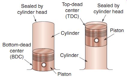
FIG. 1 A simplified drawing of a cylinder and piston. Note the position
of the cylinder at top-dead center (TDC) and bottom-dead center (BDC).
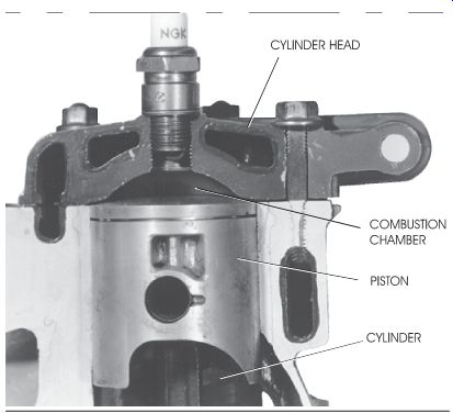
FIG. 2 The piston, cylinder, and cylinder head. The small space between
the top of the piston and cylinder head is called the combustion chamber.
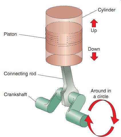
FIG. 3 The connecting rod connects the piston to the crankshaft. The reciprocating (up and-down) motion of the piston is changed to rotary (circular) motion at the crankshaft.
Reciprocating Engines
Power equipment engines use reciprocating engines. A reciprocating engine has a piston that moves alternately up and down inside a cylinder. All reciprocating engines-from tiny model airplane engines to large truck engines-have a number of common components.
FIG. 1 shows a cylinder with a piston positioned inside it. A cylinder is a circular tube that's closed at one end. The closed end of the cylinder is sealed by a cylinder head. The piston is a circular plug that moves up and down inside the cylinder. When a piston is at its lowest position in the cylinder, it's said to be at bottom-dead center (BDC). When the piston is at its highest position in the cylinder, it's said to be at top dead center (TDC).
When the piston is at TDC, a small space remains in the cylinder head. This small space above the top of the piston and below the cylinder head is called the combustion chamber (FIG. 2). In the combustion chamber, a mix ture of fuel and air is burned to produce power.
A mixture of air and fuel is introduced into the combustion chamber through the intake side of the engine. When the air-fuel mixture burns in the combustion chamber, heat is produced, and the internal gases created by the burnt air- fuel mixture expand. This expansion is strong enough to force the piston downward the cylinder. Each movement of the piston either up or down the cylinder is called a piston stroke.
The bottom of the piston is connected to the crankshaft via a connecting rod (FIG. 3). When the piston is forced downward in the cylinder, the piston's motion is transferred to the connecting rod and crankshaft. The connecting rod and crankshaft convert the up-and-down (reciprocating) motion of the piston into circular (rotary) motion. You can compare this conversion of reciprocating motion into rotary motion to the motion produced when you pedal a bicycle. When you pedal a bicycle, the up-and-down motion of your legs is converted into circular motion that drives the rear wheel.
Four-Stroke Basic Engine Operation
Today, four-stroke engines are found in almost all power equipment engines in the United States.
The primary reason for this is that four-stroke engine design is more environmentally friendly than alternative engine designs. This will be discussed in more detail in Section 6.
The basic operation of a typical four-stroke engine is divided into four events: intake, compression, power, and exhaust (FIG. 4). Here is a brief description of each event.
Intake. The piston moves downward and increases the volume of the combustion chamber, which in turn lowers the pressure to a value below atmospheric pressure. This effectively creates a vacuum that draws the air-fuel mixture into the cylinder.
Compression. The piston rises and com presses the air-fuel mixture into the combustion chamber.
Power. The air-fuel mixture is ignited by the ignition system, which creates an expansion of the gases. The expansion pushes the piston back down in the cylinder. The downward motion of the piston is transferred to the connecting rod and crankshaft.
Exhaust. The piston rises and pushes the exhaust gases out of the cylinder.
When a four-stroke engine is operating correctly, it continually runs through these events. A flywheel, which is a component that is weighted, is used to help keep the crankshaft rotating though these events.
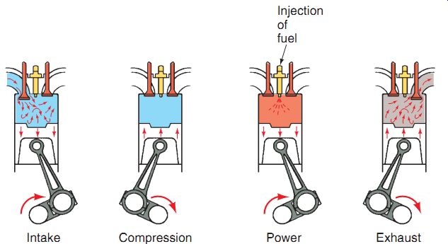
FIG. 4 The four events of the four-stroke engine in their proper sequence:
intake, compression, power, and exhaust.
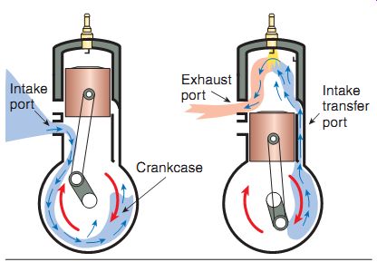
FIG. 5 The two-stroke engine uses ports to allow the intake and exhaust
gases flow through it. The piston opens and closes these ports as it goes by
them.
Two-Stroke Basic Engine Operation
The two-stroke engine operates somewhat differently from the four-stroke engine. In a four-stroke engine, the four events (intake, compression, power, and exhaust) require four piston strokes. In a two-stroke engine, these events are accomplished in only two piston strokes.
The two-stroke engine has inlet and outlet holes, called ports, located at different heights on the sides of the cylinder (FIG. 5). As the piston moves up and down in the cylinder, the ports are covered (closed) or uncovered (opened) at different points in time by the piston.
The air-fuel mixture in the two-stroke engine enters below the piston into the area around the crankshaft. The air-fuel mixture typically contains oil, to lubricate the crankshaft and related components of a two-stroke engine. The air-fuel mixture is delivered from the crankcase area to the combustion chamber through a port above the piston called a transfer port. As the air-fuel mixture enters the combustion chamber, exhaust gases are forced out an exhaust port. As the piston rises, all ports are eventually sealed off. The air-fuel mixture is compressed and ignited, producing a power stroke that forces the piston downward and transfers motion to the connecting rod and crankshaft.
ENGINE RATINGS
Now that we know the events of basic engine operation, let's take a look at how power equipment engine manufacturers rate and classify their engines. Power equipment engines are normally classified in one of the following ways:
By the size of the engine
By the amount of power the engine produces
Before we discuss how engine power is measured, let's define a few basic terms that we'll be using in this discussion.
Work
We're all familiar with the term work. People work in some way or another every day of their lives. However, when we refer to mechanical work, we actually measure the amount of work that's done. By definition, mechanical work is a force that's applied over a specific distance.
We can calculate the amount of work that's being performed by a device (or a person) by multiplying the amount of force being applied by the distance over which it's applied. Therefore, the formula for work is as follows:
Work 5 Distance 3 Force (W 5 D 3 F)
Using this formula, if the amount of force applied is measured in pounds (lb) and the distance measured in feet (ft), the amount of work performed is measured in units called foot pounds (ft-lb).
Let's look at a simple example. Suppose you move a box from the floor to a shelf. The box weighs 10 lb, and the shelf is located 5 ft from the floor. When you lifted the box and placed it on the shelf, you performed a certain amount of work. You can calculate the amount of work by using the aforementioned formula. The box weighs 10 lb; so the amount of force you applied was 10 lb. You lifted the box 5 ft off the floor; so the distance is 5 ft. Substitute these values into the formula and solve.
Work 5 5 ft 3 10 lb 5 50 ft-lb
Thus, the amount of work done in this example was 50 ft-lb.
Note, however, that this work formula doesn't mention time. The same amount of work is per formed whether you took 10 seconds or 10 minutes to move the box from the floor to the shelf. Therefore, the time required to perform the task is directly related to the strength of the person doing the job. If we don't consider the amount of time it took to perform a task, we will be unable to determine the strength of the person who did the work.
The same idea applies to power equipment engines. We can use the formula to calculate how much work an engine can perform, but without a time factor introduced, we can't determine the true strength of the engine. To calculate the engine's strength, we have to figure out the time the engine takes to complete a job.
The rate at which work is accomplished is called power. In other words, power is work done per unit of time. The following formula is used to calculate power:
Power 5 Work/Time
In this formula, we'll divide the amount of work (ft-lb) by the amount of time in ___ seconds (s). The amount of power in this case will be measured in units called foot-pounds per second (ft-lb/s).
Let's return to our example of the box and the shelf. We calculated that 50 ft-lb of work was required to move the 10-lb box from the floor onto the 5-ft-high shelf. Suppose that you completed this job in 2 s. We can use the power formula to calculate the power involved in doing the job.
Power 5 50 ft-lb/2 s 5 25 ft-lb/s
So, from our calculations, you can see that you required 25 ft-lb/s of power to complete your task.
Now that we've looked at the basic concepts of work and power, let's see how we apply this information to power equipment engine.
Horsepower
When internal combustion engines were invented, no one knew how to express the amount of work they could do. At that time, around 200 years back, horses provided most of the transportation and power. As a result, a gentleman by the name of James Watt (who we discussed in Section 1, remember?) made some observations and concluded that the average horse (of the time) could lift a 550-lb-weight over 1 ft in 1 s, thereby performing work at the rate of 550 ft-lb/s, or 33,000 ft-lb/minute (m). Watt then published those observations, stating that 33,000 ft-lb/m of work was equivalent to the power of one horse, or, 1 horsepower (hp). Thereafter, the term horse power came into existence.
1 hp 5 550 ft-lb/s
1 hp 5 33,000 ft-lb/m
Although horses are seldom used to perform work nowadays, we still use the standard unit of horsepower to describe the power output of power equipment engines. So, the next time you're looking at a power equipment engine on an implement in a showroom and it has "8 hp" marked on it, just imagine that power equipment engine being pulled by eight horses. That's pretty impressive!
Today, we rate almost all engines by their horsepower output. Stronger engines produce more horsepower. Now that you understand how to calculate horsepower, let's look at how we measure it.
There are different ways to calculate horse power. The most common way is to measure the horsepower output of an engine as it runs on a device called a dynamometer (also called dyno). A dynamometer is an instrument designed to measure power.
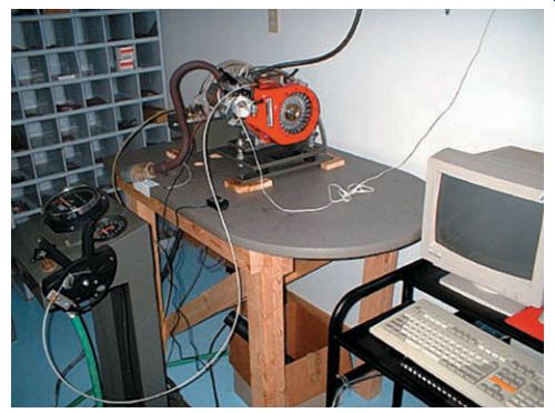
FIG. 6 A dynamometer (or a dyno) is used often in the motorcycle industry
to measure horsepower and torque.
During a typical dyno test (FIG. 6), the technician places the power equipment engine on the dyno and runs the engine at full throttle. The dyno places a load (resistance) on the crankshaft. Usually, the load is either hydraulic or electronic.
As the load increases, its force tries to prevent the engine from turning. Therefore, the engine speed decreases as the load increases. Because the load applied is a known value, the dyno can determine the amount of torque produced by the engine. If we know the torque produced, we can calculate the horsepower of the engine.
Because this type of test involves the slowing or braking of the engine, the type of horsepower measured this way is commonly referred to as the brake horsepower (bhp). The brake horse power rating is the maximum power output of the engine. You'll usually see the specifications for an engine given in bhp.
In practical use, a power equipment engine is normally operated at a level well below its maxi mum power output. If the engine is run always at its maximum horsepower, it would have a very short life span.
You can compare an engine that's running at its maximum rated power to a person running at top speed. That person wouldn't be able to keep up that pace for long; neither would an engine running at its maximum horsepower.
Torque
Torque, as mentioned in Section 3, is a measure of twisting or rotational force. Remember that an engine's output is in the form of rotational motion. The power output from the crankshaft is used to turn another piece of equipment, such as a lawnmower blade, snow thrower auger, or the wheels of a go-cart.
You can compare the torque produced by an engine to the twisting force a person exerts when opening a jar lid. Engine torque is usually measured in foot-pounds and can be measured on a dynamometer.
FIG. 7 A typical dynamometer chart shows horsepower and torque over a wide range of engine revolutions per minute (rpm).
As you've probably figured out by now, the ideal engine would have a high horsepower and torque rating. Unfortunately, we don't see this combination too often in real life. In a typical power equipment engine, the horsepower and torque that are developed will vary with the speed of the engine (FIG. 7). This speed is measured in revolutions per minute (rpm), which is a measure of how many complete turns (360°) the crankshaft makes in 1 minute.
In a typical engine, horsepower generally increases as rpm increases. Remember that power is related to the rate (speed) at which work can be done. Therefore, the maximum horsepower develops near the maximum rpm limit of the engine. Torque, on the other hand, is produced somewhat differently. The maximum torque is normally produced at a lower rpm range and then declines as the rpm increases. This means that the maximum torque and the maximum rpm don't usually occur at the same time.
So, when manufacturers design power equipment engines, they must compromise. The design usually depends on the particular application.
More torque usually means better acceleration and more low-end power. Higher horsepower usually means higher top speed capabilities. The amount of horsepower and torque an engine develops depends on many design factors. The displacement, compression ratio, fuel mixture, engine design, ignition timing, and valve timing (in four-stroke engines) all affect horsepower and torque.
Engine Displacement
When you hear people refer to the size of an engine, they don't mean the overall size of the engine but rather the size of the area inside the engine where the air-fuel mixture is burned.
The size of this area is known as the engine displacement.
By definition, engine displacement is the volume of space through which the piston moves as it moves from BDC to TDC. The distance that the piston travels up or down in a cylinder is called the stroke of the engine (FIG. 8). The inside diameter of the cylinder is called the bore. Displacement in power equipment engines is generally measured in cubic centimeters (cc); but it may also be measured in cubic inches (ci). The displacement of an engine is usually stated in the service manual and often stamped on the engine itself.
You can calculate the displacement of an engine if you know the diameter of the cylinder and the length of the stroke of the engine's crankshaft:
Displacement 5 B2 3 0.7854 3 S 3 N
In this formula, B stands for the diameter (bore) of the cylinder. The number 0.7854 rep resents a constant, which is a number used in a formula that never changes. S stands for the stroke of the engine and N for the number of cylinders in the engine.
To see how this formula works, let's look at an example. Suppose an engine has one cylinder with a diameter of 73 millimeters (mm). The stroke of the engine is 58 mm. To calculate the displacement, we must first convert millimeters into centimeters (cm). Many power equipment engines are rated in cubic centimeters. Simply moving the decimal point one space to the left does this: 73 mm equals 7.3 cm (remember that 1 cm equals 10 mm). Substitute these values into the formula to determine the size of the engine.
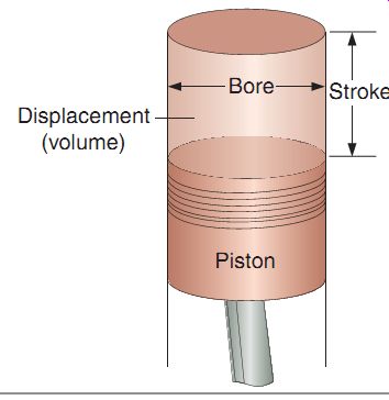
FIG. 8 The bore and stroke of an engine.
This information is used to determine engine displacement.
Displacement 5 7.3 cm (bore) 3 7.3 cm (bore) 3 0.7854 3 5.8 cm (stroke) 3 1 (number of cylinders) 5 242.753 cc
This example is for an 8-hp power equipment engine. Note that the power equipment engine manufacturer will round off the displacement number to indicate the size of the engine. In this case, the engine displacement would be 243 cc.
We can use the same formula to determine the displacement of an engine in cubic inches.
For instance, if we have a single cylinder engine with a bore of 2.67 inches and a stroke of 1.96 inches, the displacement equation would look like this:
Displacement 5 2.67 in (bore) 3 2.67 in (bore) 3 0.7854 3 1.96 in (stroke) 3 1 (number of cylinders) 5 10.974 cubic inches (ci)
This example is for a 6-hp power equipment engine.
Note again that the power equipment engine manufacturer will round off the displacement number to describe the size of the engine, which in this case would be 11 ci.
An engine's displacement has an effect on the power that the engine develops. In most cases, the larger the displacement, the more power the engine will develop. However, this doesn't mean that a smaller engine can never develop more horsepower than a larger one. There are many factors besides displacement that affect an engine's power. However, in general, an engine with a larger displacement will develop more horsepower.
Compression Ratio
You have learned that the displacement of an engine is the volume of space through which a piston moves as it travels up and down in a cylinder. When a piston is at BDC, the cylinder volume (CV) is at its largest. When the piston is at TDC, the cylinder volume is at its smallest.
When the cylinder is at its smallest volume position, it's said to be at its combustion chamber volume (CCV). The ratio of the largest cylinder volume to the smallest cylinder volume is called the compression ratio (FIG. 9). A ratio is simply a comparison between two values. The compression ratio can be calculated by using the following formula:
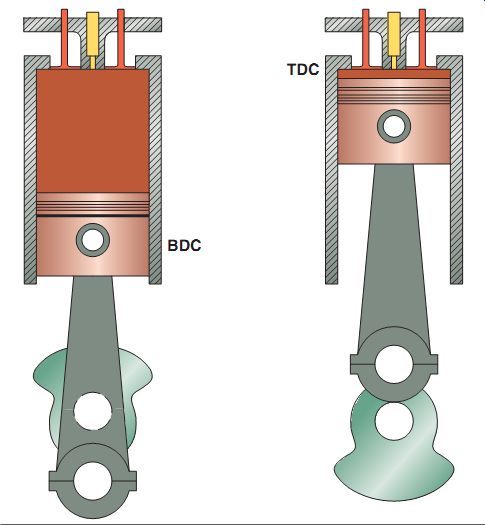
FIG. 9 The TDC as well as BDC of a piston. Knowing the volume of the cylinder
in these positions allows us to determine the compression ratio.
Compression ratio 5 CV/CCV
The volumes at BDC and TDC can be determined by using a combination of mathematical calculations and special test instruments. The typical technician will never be required to measure these volumes, so we won't get into the details of how the volumes are determined. However, you should be aware that the compression ratio of an engine affects the amount of power that the engine develops.
Let's examine the compression ratio in a typical power equipment engine. For example, CV at BDC is 80 cc and CCV is 10 cc. The compression ratio of this engine is therefore 8 to 1. This ratio may be written as 8 to 1 or abbreviated as 8:1.
The compression ratio is important in a power equipment engine because it determines how effectively fuel is burned in the cylinder. As you learned earlier, fuel burns inside the cylinder to produce power.
An engine's compression ratio determines how much the fuel mixture will be compressed when the piston rises. The higher the compression ratio, the more the mixture is compressed. Our example engine had a compression ratio of 8 to 1. This means that when the air-fuel mix ture first enters the cylinder, the mixture has a potential volume of 80 cc. When the piston is at TDC, the 80 cc of mixture is compressed into a 10-cc space. When this compression occurs, the pressure of the mixture increases dramatically.
This large increase in pressure helps the mixture burn more completely and produce more power when it's ignited. The compression ratio is an important parameter in engine specifications.
If an engine's compression ratio is too high, the excessive pressure can damage the engine.
If the compression ratio is too low, the engine may not develop much power. Different engines have their own specified compression ratios.
BASIC FOUR-STROKE ENGINE COMPONENTS
Now that we've established the required components of a simple internal combustion engine, let's discuss ways of making it work for us as a suitable power equipment engine power source.
To best explain the basic design of a typical four-stroke engine used in a power equipment engine, we will cover the main components found in a single cylinder four-stroke engine. Most power equipment engines will be found with single cylinder four-stroke engines. The single cylinder four-stroke design is the least complex of all four-stroke engine configurations and can come in a horizontal (FIG. 10) or vertical (FIG. 11) crank shaft configuration. This configuration is key to the type of implement that the engine is being attached to. For instance, a lawnmower will use a vertical-type engine, whereas a go-cart would use a horizontal-type design.
Cylinder Block/Crankcase--The engine cylinder block (also referred to as a crankcase by some manufacturers) is used to hold all engine components together and pro vide the main engine mounting points (FIG. 12). The cylinder block material may be iron or aluminum. Sometimes, the cylinder may comprise an aluminum block with an iron-sleeved cylinder. In many power equipment engines, the cylinder block also contains the intake and exhaust valves, which are used to allow air and fuel into the engine as well as expel the gases once combustion has occurred.
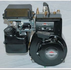
FIG. 10 A single cylinder horizontal four stroke engine.
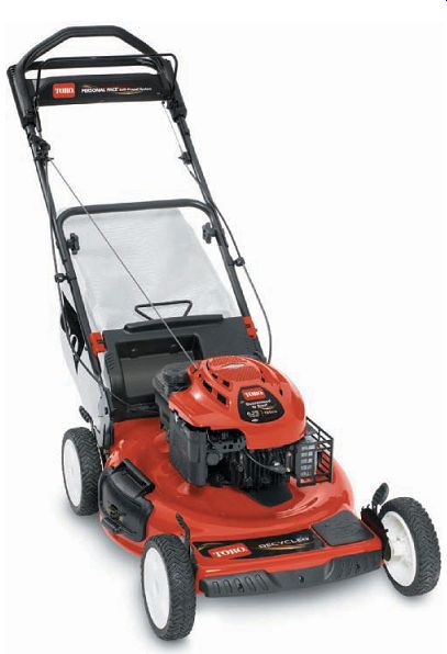
FIG. 11 A single cylinder vertical four-stroke engine mounted on a lawnmower.
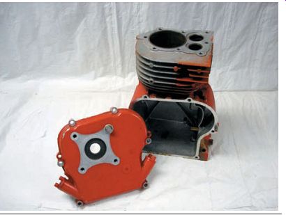
FIG. 12 Four-stroke power equipment engines use a cylinder block that
holds all engine components together and provides for the main engine mounting
points. A cover is used to access the components inside the engine.
Crankshaft
Four-stroke crankshafts in almost all power equipment engines are made to a one-piece design (FIG. 13). They will have connecting rods that attach to the piston. At least one bearing on each end supports the crankshaft and allows it to rotate freely. The crankshaft is located in the engine cylinder block.
Seals
Seals (FIG. 14) are used to protect rotating shaft bearings. Seals are located typically at the ends of rotating shafts that go outside of the cylinder block. These seals prevent gases and oil from escaping from the cylinder block and also prevent outside substances from getting into the block.
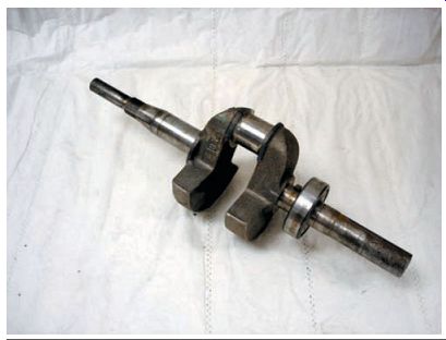
FIG. 13 A one-piece crankshaft without the connecting rod.
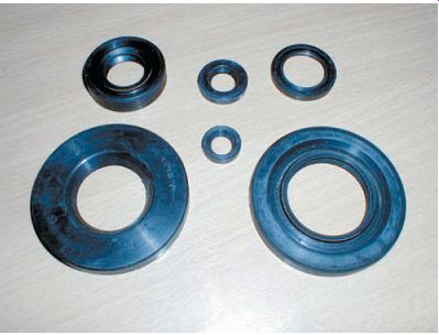
FIG. 14 Seals used in engines protect the rotating shafts and seal in
lubricants and prevent outside contaminants from getting into the engine.
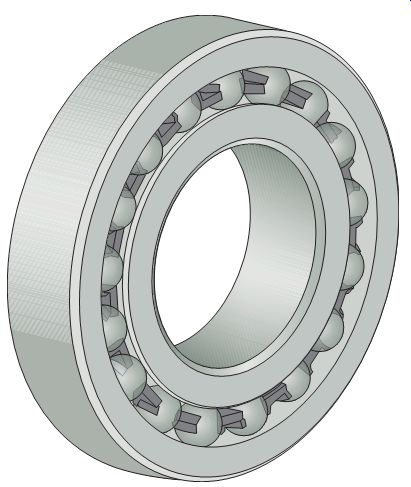
FIG. 15 A typical ball bearing.
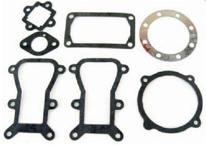
FIG. 16 Gaskets are used to seal the mating surfaces of various parts
of the engine.
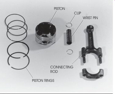
FIG. 17 A four-stroke engine piston and its related components.
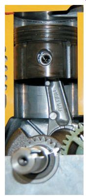
FIG. 18 Piston rings are located in the slots on the outside diameter
of the piston to make a seal between the piston and cylinder wall.
The piston travels up and down in the cylinder, as shown in this cutaway.
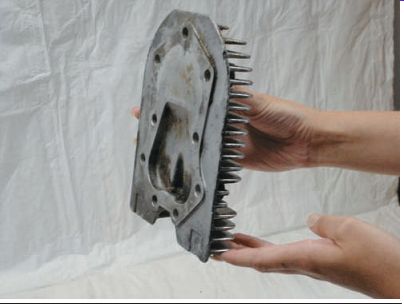
FIG. 19 Heads on engines that have the valve mechanism in the cylinder
block have no moving parts. Note the fins that are used to assist in cooling
the engine.
Bearings
Bearings (FIG. 15) are found primarily in the cylinder block of the four-stroke engine.
Bearings are designed to reduce friction and allow shafts to rotate freely under various engine loads.
Gaskets
Gaskets (FIG. 16) are used to seal the mating surfaces of various parts of the engine.
Typically, the two surfaces are metallic. The gasket material may be rubber, cork, paper, or metal.
Piston
The piston is attached to the crankshaft via the connecting rod. The piston is held in place by a wrist pin. Clips prevent the pin from moving.
The wrist pin usually has a bushing between it and the connecting rod. Piston rings are located in the slots on the outside diameter of the piston to make a seal between the piston and cylinder wall (FIG. 17). The piston travels up and down in the cylinder, which is usually positioned at a 90° angle from the crankshaft (FIG. 18).
Cylinder Head
The cylinder head is attached to the cylinder block to seal the top of the cylinder from the outside of the engine and also forms the combustion chamber. Heads on engines that have the valve mechanism in the cylinder block have no moving parts (FIG. 19). Engines that contain the valve mechanism located in the head are more complex and contain holes that are called ports (FIG. 20). These ports are opened and closed with valves.
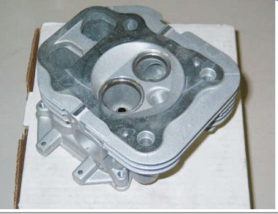
FIG. 20 Engines that contain the valve mechanism in the head are more
complex and contain holes that are called ports. These ports are opened and
closed with valves.
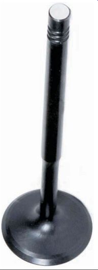
FIG. 21 The valves in a four-stroke engine control the air-fuel mixture
that's drawn into the cylinder and the exhaust gases that are expelled.
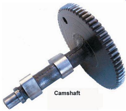
FIG. 22 A typical camshaft used in a power equipment engine.
The valves (FIG. 21) in a four-stroke engine control the air-fuel mixture that's drawn into the cylinder and the exhaust gases that are expelled. These valves are actuated by a cam shaft (FIG. 22). Camshafts are normally located in the cylinder block. The camshaft is generally connected to the crankshaft with a timed gear drive and uses lifters and push rods to open and close the valves.
Counter-Balancer
Many manufacturers of single cylinder engines use a gear or chain-driven counter balancer to offset the uneven forces that create vibration and help keep the engine running smoothly. A counter-balancer is a device that balances the power pulses created by the power strokes (FIG. 23). Although using a counter balancer requires additional parts, it requires very little maintenance.
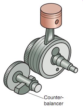
FIG. 23 Counter-balancers are used to help some four-stroke engines run
smoother by subsiding vibration.
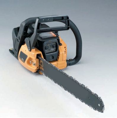
FIG. 24 The single cylinder two-stroke engine is the least complex of
all two-stroke designs. Shown here is a chain saw powered by a two-stroke engine.
Starting Devices
The last part of the bottom end is the starting mechanism. The four-stroke engine uses one of two starting mechanisms.
The recoil starter mechanism uses a pull cord that's attached to a pulley on the crankshaft.
The operator pulls the cord to turn the crankshaft. The cord has a return spring to rewind it into the housing.
The electric start mechanism is similar to an automobile's starter mechanism. It uses an electric motor with a reduction gear to turn the engine's crankshaft. The operator energizes the starter motor with a push-button or key-lock mechanism.
BASIC TWO-STROKE ENGINE COMPONENTS
Now we'll cover the two-stroke engine's major components and their layout. We'll discuss in detail how these components work in Section 6, but for now, let's concentrate on the basics. The two-stroke engine is the least complex engine as far as components are concerned (FIG. 24).
A two-stroke engine has most of the same components as a four-stroke engine: a crank case, crankshaft, seals, bearings, gaskets, and a starting mechanism. Only minor differences exist regarding the actual components.
Cylinder Block/Crankcase
Engine crankcases are used to hold all engine components together and supply the main engine mounting points. There are often two crankcases: center and side. The center crank case holds all major components together. The side crankcase enables you to gain access to the various parts of the engine without having to fully disassemble it. Side crankcases are also known as side covers.
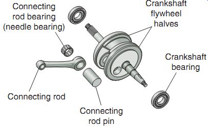
FIG. 25 The parts of a single cylinder two stroke engine.
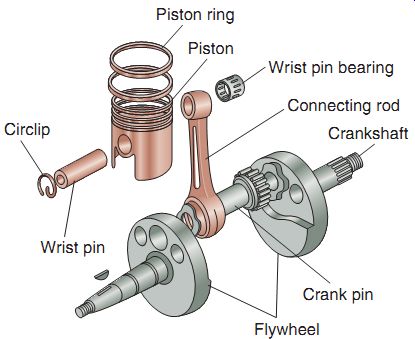
FIG. 26 The piston and its related parts are attached to the crankshaft
via the connecting rod.
Crankshaft
The two-stroke crankshaft is made up of two flywheel halves, a connecting rod, a connecting rod pin, and a connecting rod bearing (FIG. 25). A bearing on each end supports the crankshaft and allows it to rotate.
Seals and Bearings
As in four-stroke engines, seals in two-stroke engines are used to protect rotating shaft bearings. The seals are typically located at the ends of the rotating shafts. These seals prevent the loss of gases and oil from the crankcases. Their sealing action also prevents outside substances and air from getting into the crankcases.
Bearings are found primarily in the crank case of the two-stroke engine and perform the same function as in the four-stroke engine: reduce friction and allow shafts to rotate freely under various engine loads.
Gaskets
Just as in four-stroke engines, gaskets in two-stroke engines are used to seal the mating surfaces of various parts of the engine. These surfaces are usually both metallic. The gasket material may be rubber, cork, paper, or metal.
In some instances, the surface is machined so precisely that no gasket is needed; instead, a thin layer of liquid sealant is used.
Starting Devices
The most common starting device found in two-stroke engines used in power equipment is of the recoil-pull-start variety. The recoil starter consists of a rope, a handle, and a spring device that allows the starter to return after it has been pulled.
Piston
The piston is attached to the crankshaft via a connecting rod (FIG. 26). The piston is held in place by a wrist pin. Clips prevent the wrist pin from moving laterally. There's usually a bearing where the piston pin attaches to the connecting rod. Each piston has one or more rings around its outside surface. These rings are called piston rings. The rings form a seal between the piston and the cylinder surfaces to improve the compression and exhaust functions. Small pins in the ring lands prevent the rings from moving into the ports of the cylinder.
Cylinder and Cylinder Head
A two-stroke engine's cylinder is the most complex component in the engine. The two stroke engine cylinder has holes in it called ports. The ports allow fuel mixtures to enter the cylinder and exhaust gases to be removed from the cylinder (FIG. 27). The cylinder head is attached to the cylinder and seals the top of the cylinder from the outside of the engine. Different types of two-stroke induction systems have their ports located in different areas.
ENGINE COOLING
A significant amount of heat is generated in any internal combustion engine during the combustion stage of the engine's operation.
All engines must have a way to dissipate this heat because excessive heat will damage the components. Power equipment engines use one of two ways of maintaining ideal operating temperature-air-cooling and liquid-cooling temperature control.
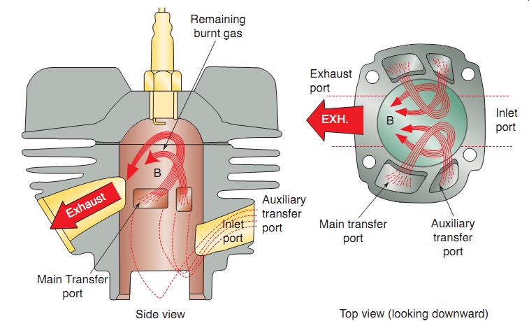
FIG. 27 The ports in a two-stroke cylinder allow the flow of gases in
and out of the engine, using the piston to open and close them.
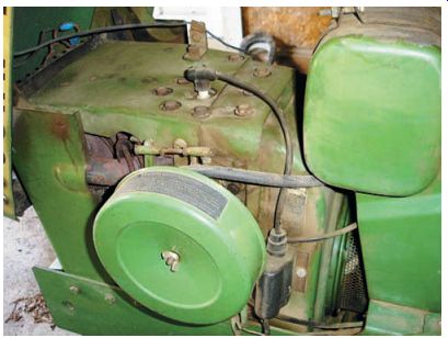
FIG. 28 This air-cooled engine is completely covered in shrouds. Air-cooled
power equipment engines use an engine-driven fan attached to the flywheel to
move air and keep the engine running cool.
Air-Cooled Engines
Air-cooled engines use cooling fins in the cylinder block and the cylinder head to remove excess heat from the engine. In power equipment engines, air cooling is achieved by using a forced draft design. The forced draft design uses air from an engine-driven fan that is attached to the crankshaft-mounted flywheel to move cool air through ducts. These ducts, called shrouds, surround the engine and keep it cool by forcing the air in toward the cylinder and head fins (FIG. 28).
Liquid-Cooled Engines
The main difference between an air-cooled engine and a liquid-cooled engine is the use of liquid instead of air to maintain proper engine operating temperature. This liquid is usually made up of a 50/50 mixture of distilled water and anti-freeze (ethylene glycol). The cylinder and cylinder head have water jackets. A water jacket (FIG. 29) comprises a series of passage ways surrounding the cylinder and combustion chamber. As the liquid circulates through these passageways, the heat is transferred from the metal to the liquid, which helps to control the internal heat of the engine.
Other components such as the radiator, water pump, thermostat, hoses, and a reservoir tank assist with circulation and cooling of the liquid coolant. The prime advantage of liquid cooling is that the engine is maintained at a constant temperature. Another advantage with liquid-cooled engines is that the engines run quieter because the liquid coolant provides sound dampening to the internal engine noises.
ENGINE CONFIGURATIONS
Now that you have a preliminary under standing of basic engine components, let's take a look at the different engine configurations in a power equipment engine. The obvious difference between a single cylinder engine and a multi-cylinder engine is the number of cylinders and pistons. Multi-cylinder engines run more smoothly because there are more power strokes per 360° of crankshaft rotation. In most cases, more cylinders also means more displacement and more power. Multi-cylinder engines may be either air cooled or liquid cooled. Here are the main types of engine configurations.
Single Cylinder Engines
By far the most popular power equipment engine configuration, the single cylinder engine has a single piston and is primarily air cooled (FIG. 30).
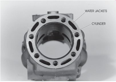
FIG. 29 The liquid-cooled engine has water jackets surrounding the cylinder.
Horizontally Opposed Twin-Cylinder Engines
On horizontally opposed twin-cylinder power equipment engines, the cylinders oppose one another. The crankshaft in this engine configuration will always be of a 180° design. Because the cylinders oppose each other, the pistons move in and out at the same time and keep the engine in balance.
V-Twin Engines
The V-twin engine design (FIG. 31) allows for the greatest amount of engine displacement in the smallest overall area.
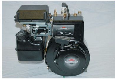
FIG. 30 The most common type of power equipment engine is of the single
cylinder variety.
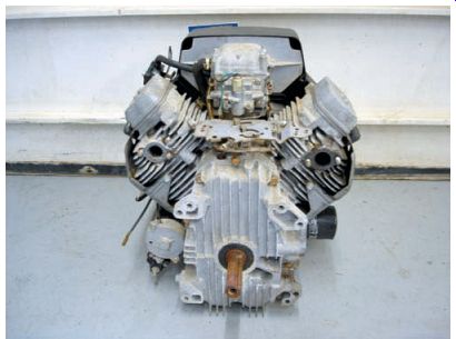
FIG. 31 A V-twin engine.
Summary
All power equipment engines use reciprocating engines as a source of power.
There are two types of power equipment engines: two-stroke and four-stroke engines.
Engines are rated by the amount of horsepower and torque that they produce.
There are distinguishable components found in two-stroke and four-stroke engines.
There are two basic types of engine cooling systems used in power equipment engines.
There are different engine configurations found in power equipment engines.
QUIZ
1. The single cylinder four-stroke engine has a power stroke every ° of crankshaft revolution.
2. During which stage of engine operation does the burning mixture of air and fuel force the piston downward in a four-stroke engine?
a. Compression
b. Power
c. Intake
d. Exhaust
3. The four, basic four-stroke engine operation events, in their proper sequence, are
a. compression, intake, power, exhaust.
b. intake, compression, power, exhaust.
c. power, compression, intake, exhaust.
d. intake, power, compression, exhaust.
4. By definition, work is a force that is applied over a specific .
5. Work/Time 5
6. What would the compression ratio be if a cylinder has a volume of 250 cc and a combustion chamber volume of 20 cc?
a. 0.08:1
b. 8:1
c. 10:1
d. 12.5:1
7. When the piston is at its highest point, it's said to be at
a. TDC.
b. BDC.
c. ABC.
d. BBC.
8. What is the name of the device used to measure engine torque and horsepower?
a. Manometer
b. Compressor
c. Dynamometer
d. Vernier caliper
9. A measurement of the twisting or rotational force that an engine can produce is called
a. rotary distance.
b. horsepower.
c. torque.
d. compression ratio.
10. The connecting rod and crankshaft convert up-and-down (reciprocating) motion into:
a. a small, contained explosion.
b. rotary motion.
c. a release of exhaust gases.
d. movement in the cylinder head.