AMAZON multi-meters discounts AMAZON oscilloscope discounts
Goals:
- Identify the basic measuring systems used on power equipment engines
- Identify common fasteners used on power equipment engines
- Describe the four most important bolt dimensions
- List the three basic types of threads used on fasteners
- Understand how to identify and record bolt grade/tensile strength
- Determine the appropriate tightening torque for a threaded fastener
- Describe common ways to remove damaged fasteners
- Describe how to clean and repair damaged threads
INTRODUCTION
Power equipment engines use two systems of weights and measurement. Most power equipment engines made in the United States use the U.S. or conventional system of weights and measurement. Virtually all power equipment engines built in the rest of the world use the metric system, which is considered by many to be easier to use.
Power equipment engines have hundreds of parts held together by threaded fasteners. Unlike permanent fastening methods like welding, riveting, or gluing, threaded fasteners establish a non-permanent connection that can be disassembled when necessary.
A competent power equipment engine technician must know the different measurement systems as well as about fasteners, including how to properly install and tighten the various fasteners to correct manufacturer specifications and how to repair and remove fasteners when they break.
A technician must be able to use a torque wrench to complete most tightening procedures to ensure a quality reassembly. In doing so, the technician must be able to use factory-specified torque values and recommended tightening methods and sequence of operations. An improperly tightened fastener can fail by loosening (backing out) or breaking, causing a dangerous condition for the operator of the power equipment engine. In this section, we will review measurement systems, fastener identification and classification, removal of broken and seized fasteners, thread repair procedures, and fastener reinstallation guidelines.
MEASUREMENT SYSTEMS
For power equipment engine systems to operate properly, the parts must fit together securely. Fasteners, parts, and the tools needed to work on them are made to specific sizes or measurements.
Power equipment engine manufacturers use the two most common weights and measurement systems: the conventional system and the metric system.
The Conventional System
Use of the conventional system, also known as the standard or United States Customary system, requires knowledge of different combinations of numbers. For example, 1 foot contains 12 inches. One inch can be divided into equal units, as in halves (1/2"), quarters (1/4"), or eighths (1/8") of an inch. Rulers and other measuring instruments divide each inch into units of 16, 32, 64, or 128 equal parts.
Sizes of fasteners, tools, and parts are stated in inches or parts of inches. The parts of inches are expressed either as fractions or as decimal numbers. For example, a fastener diameter of one-half inch can be written as 1/2" or as a decimal, 0.5", and a fastener diameter of 1/8" would be 0.125" as a decimal number.
The Metric System
The metric system, also called the International System of Units (SI), is used in virtually all countries around the world. It's easier to use because it uses a simple decimal system to deter mine different base units of measurement.
There is no need to memorize, for example, that 12 inches make a foot or 3 feet make a yard.
Power equipment engines generally use the following metric increments, the meter being the base point of measurement:
- A millimeter equals one thousandths (1/1000) of a meter.
- A centimeter equals one hundredth (1/100) of a meter.
The metric system uses only decimal numbers. It's easy to remember that each metric unit of measurement is 10 times the size of the previous unit. For example, 10 millimeters (10 mm) equal 1 centimeter (1 cm), and 10 centimeters (10 cm) equal 1 decimeter (1 dm). A meter (39.37 inches) equals 1,000 mm or 100 cm. Each metric unit of measurement smaller than the meter equals 1/10 (0.10) the size of the previous unit. Thus 1 centimeter equals 0.01 meter and 1 millimeter equals 0.001 meter.
FASTENERS
Fasteners are devices that hold the parts of a power equipment engine together. Hundreds of fasteners are used in today's modern vehicles.
FIG. 1 illustrates some of the most common types.
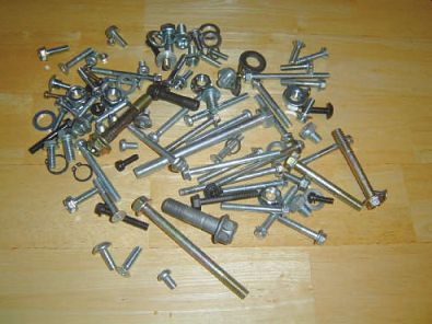
FIG. 1 Many of the common types of fasteners used on today's power equipment
engines.
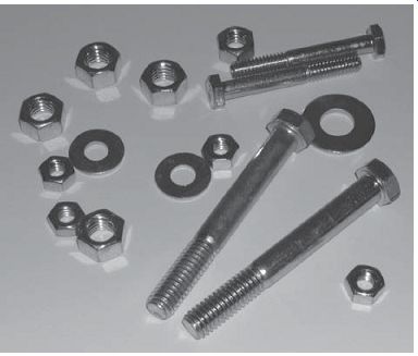
FIG. 2 Examples of nuts, bolts, and washers.
The Nuts and Bolts of Bolts and Nuts
A bolt is a metal rod with external threads on one end and a head on the other. When a bolt is threaded into a part other than a nut, it can also be called a cap screw. A nut has internal threads and usually is made with a six-sided outer shape.
FIG. 2 shows examples of bolts, nuts, and washers. When a nut is threaded onto a bolt, a powerful clamping force can be produced.
In power equipment engine technology, many bolts and nuts are named after the parts they hold. For instance, bolts holding the cylinder head on the block are called cylinder head bolts. Bolts on an engine-connecting rod are called connecting rod bolts.
When more turning force, or torque, is applied, the greater force exerted on the nut creates a tension in the bolt, which clamps the mating parts together. Preload is the technical term for the tension caused by tightening the fastener that holds the parts together. The common term used for this is torque. Producing sufficient preload force is the key to strong and reliable bolted joints that will not loosen or break under load. FIG. 3 illustrates the forces that act on a bolted component. We will discuss these forces later in this section.
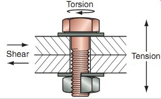
FIG. 3 The forces acting on a threaded fastener: axial tension, torsion,
and shear.
Fastener Anatomy
Bolts and nuts come in various sizes, grades (or strengths), and thread types. A good technician must be familiar with the differences. The four most critical bolt dimensions (FIG. 4) are:
Bolt diameter. The outside diameter of the bolt threads.
Head size. The distance across the flats or outer sides of the bolt head. This is the same as the size of the wrench that would be used to install or remove the bolt.
Bolt length. The distance from the bottom of the bolt head to the threaded end of the bolt.
Thread pitch. Sometimes referred to as thread coarseness, thread pitch for metric fasteners is the distance from the top of one thread to the top of the next (FIG. 5). The Inter national Standards Organization (ISO) sets these specifications. This is also the distance the bolt moves in one complete revolution.
Standard or U.S. Customary (USC) fastener thread pitch is determined by the number of threads per inch (TPI) (see FIG. 6 for thread pitch measurement using the conventional system).
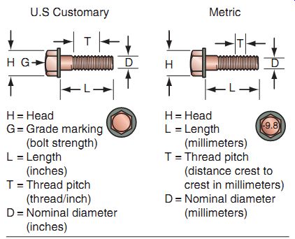
FIG. 4 Critical bolt dimensions, in the United States Customary (USC)
and metric systems.
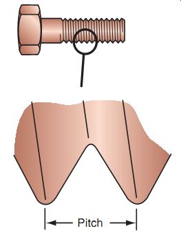
FIG. 5 Thread pitch is the distance from the top of one thread to the
top of the next.
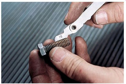
FIG. 6 A thread pitch gauge that measures threads per inch.
Thread Types
With respect to thread standards, there is a metric thread (SI), a parallel thread for piping (PF), a taper thread for piping (PT), and a unified thread [unified national coarse (UNC), unified national fine (UNF)].
The three most common types of threads used on fasteners are:
Coarse threads (UNC)
Fine threads (UNF)
Metric threads [System International (SI)]
An additional thread is used on power equipment engines but in limited applications. For example, threads on oil pressure switches and coolant temperature sensors may use a PT (tapered pipe) or a PF (standard pipe) thread.
Note that PT and PF threads are not compatible with each other or any other threads previously mentioned.
Never substitute thread types or else thread damage will result. To prevent damage to fasteners, always thread the bolt or nut by hand (or fingers) for the first 3-5 complete turns. If the fastener only threads a turn or two and then starts to bind, there may be a mismatch. Don't continue to tighten using a big wrench, air tool, or impact wrench as damage will likely occur.
Bolts and nuts come in right-hand and left hand threads. With right-hand threads, the fastener must be turned clockwise to tighten. This is the most common style of thread. A left hand thread requires turning the fastener in a counterclockwise direction to tighten. Left-hand threads are not common. The letter "L" may be stamped on fasteners with left-hand threads.
Bolt Grades
Tensile strength, or grade, refers to the amount of pull a fastener can withstand before breaking. Bolts are made out of different metals. Some are better than others.
Tensile strength of bolts can vary. Bolt head markings, also called grade markings, specify the tensile strength of the bolt. Standard or USC bolts are identified with lines or slash marks (FIG. 7). Count the lines and add 2 to determine the strength of the bolt. These are known as Society of Automotive Engineers (SAE)-type and are evaluated by the American National Standards Institute (ANSI).
Metric bolts are numbered: The higher the bolt number, the greater the strength of the bolt (FIG. 7). The ISO defines fastener quality in terms of tensile strength and yield strength.
This standard is used for metric fasteners and may someday eventually replace all other grading standards. Metric fasteners classified as 8.8 or higher are required to have the markings.
When replacing any bolt, always replace with the same grade markings. A weaker bolt may easily snap causing part failure and a dangerous condition. Replacing a bolt with a stronger one isn't always safe. Harder bolts tend to be more brittle and may fail in specific applications.
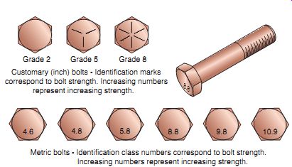
FIG. 7 Typical bolt grade markings.
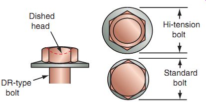
FIG. 8 A deep recess (DR)-type bolt.
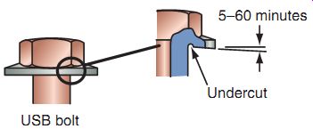
FIG. 9 Uniform bearing stress (UBS) bolts have flanges that flex to resist
loosening.
Bolt Types
There are various types of bolts found on power equipment engines. Here, we will cover a few of the most commonly found.
Deep Recess-Type Bolts
Deep-recess (DR)-type bolts without strength markings (flange bolts with hex-heads and weight reduction recess in them) are classified by outer flange diameters (FIG. 8). Their outer flange diameters are larger than those of standard bolts with a flanged head. Install these bolts in the correct location with the correct torque.
Uniform Bearing Stress Bolts
Uniform bearing stress (UBS) bolts (FIG. 9) are designed to resist loosening. A small angle of 5-60' is rolled or forged on the underside of the bolt head. This causes the flange to flex as the bolt is tightened and pro vides additional friction to hold the bolt tight.
UBS bolts can be identified by an undercut radius under the bolt head. UBS bolts may or may not be marked with strength marks.
Torx Bolts
Torx bolt heads (FIG. 10) have a patented shape. Bolts of this design carry a greater torque from the socket to the bolt. These bolts come in both external and internal types. The external Torx is classified as an E type and the internal as a T type. These are used on many ATV differentials.
Combination Bolts
The combination (CT) bolt is a type of self tapping bolt (FIG. 11). It forms the female threads when it's screwed into the unthreaded pilot hole by deforming the walls of the hole.
The lower half of the CT bolt features the combination of the standard threads and the low threads. Fewer chips and shavings are produced while using a CT bolt.
Note: When the CT bolt is reinstalled, be sure that the male threads drop into the female threads in the component before tightening to prevent forming another set of threads. When replacing a CT bolt (FIG. 12), use a new CT bolt or a standard bolt of shorter length.
Studs
A stud (FIG. 13) is a fastener with external threads on each end. To hold parts together, a stud first is tightened into a threaded hole in a part (such as an engine case). A second part (a cylinder head) fits over the exposed end of the stud. Finally, a nut is fitted to the exposed end of the stud and is tightened. Studs generally come in two thread sizes, to enable the user to be sure which side of the stud should be inserted into the threaded hole. Studs are removed by the use of a puller, also seen in FIG. 13.
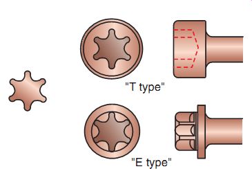
FIG. 10 The two types of Torx bolts.
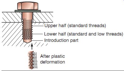
FIG. 11 Combination (CT) bolts are self tapping.
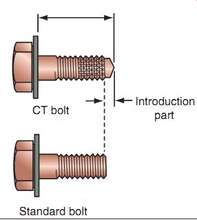
FIG. 12 When replacing a CT bolt with a standard bolt, use a shorter bolt
or else you could damage the component.
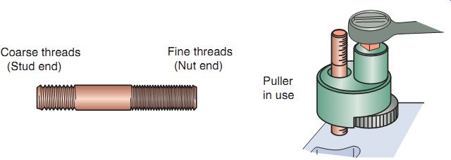
FIG. 13 Studs have external threads on both ends.
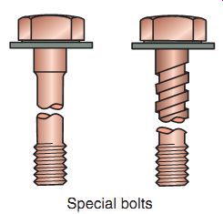
FIG. 14 Special bolts are used in various places on a power equipment
engine. Be sure to use the correct bolt when reassembling!
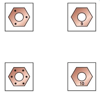
FIG. 15 Grade markings on nuts are used in the same fashion as on bolts.
Tension Bolts
Certain areas of the power equipment engine are subjected to repeated and severe external forces, such as vibration or expansion due to heat. Special bolts (FIG. 14) with greater elasticity are used in these areas. These fasteners stretch further than common bolts without permanently stretching. They're used on cylinder heads, connecting rods, and crankcases.
Nuts
A nut has internal threads and usually a six sided outer shape. The grade of nut used must match the grade of bolt that it's used with. Manufacturers use different nut markings for grade identification (FIG. 15). Some marks are on the top and others are marked on the sides.
Self-Locking Nuts
A self-locking nut (FIG. 16) has a spring plate on the top. This spring plate presses against the thread, making it difficult for the nut to loosen. This type of nut, which can be used again after removal, can be found on the frame, in suspension pivot bolt/nut applications, and the axle. Points to consider when working with self-locking nuts are:
The bolt head must be held during nut installation and removal because of the resistance of the nut spring plate against the bolt.
If the bolt length is too short, the spring plate portion of the lock nut will not engage the thread fully. Therefore, the nut will not lock.
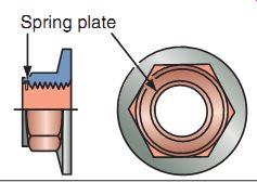
FIG. 16 A self-locking nut with a spring plate.
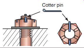
FIG. 17 Castle-headed nuts are used with cotter pins to prevent loosening.
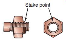
FIG. 18 Stake-type lock nuts are usually used inside engines.
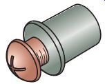
FIG. 19 Well nuts are used mainly on plastic parts like windshields. They
expand when tightened.
Castle-Headed Nuts
The castle-headed nut allows a cotter pin (FIG. 17) to be installed through a nut and bolt to prevent loosening. Applications include important safety points on the frame, axle nut, and brake torque rod. Points to consider when working with castle nuts are:
Always use new cotter pins during assembly.
Tighten the nut to the specified torque.
Align the next possible pinhole while tightening the nut just beyond the specified torque.
Don't align the holes in a position where the nut torque is less than the specified torque.
Stake Nuts--The stake-type lock nut (FIG. 18) incorporates a metal collar at the top of the nut.
A punch is used to stake (bend or indent) the collar of the nut to match a groove in the shaft that it's being used on. Applications include the clutch center lock nut, shift drum stopper plate, and wheel bearing retainers. Points to consider when using stake nuts are:
During disassembly, eliminate the staking point before the nut is loosened.
Replace the nut if the old staked area of the nut aligns with the groove of the shaft after tightening the nut to the specified torque.
After tightening the nut to the specified torque, stake the nut collar using a drift punch. Ensure that the staking point has entered into the grove at least 2/3 of the groove depth.
Well Nuts--Well nuts are rubber fasteners with a brass threaded sleeve installed in the center (FIG. 19). A screw normally threads into the brass insert. When tightened, the insert causes the rubber to expand and hold it in place. Well nuts are used on body panels, fairing parts, and windshields/ windscreens. Don't use excessive force to tighten well nuts.
Acorn (Cap)--Nuts An acorn nut or cap nut (FIG. 20) is a decorative nut with a finished or plated surface and is used often to cover the threaded end of a bolt or stud. Many are made of stainless steel to prevent corrosion or chipping. Bolts (or studs) must be of proper length or else the nut may bottom on the stud before the clamping action can occur. Applications include head nuts and engine covers.
Washers--There are several types of washers common to the power equipment engine industry.
Flat Washers--A plain flat washer is used under bolt heads and nuts. Use of correct-sized washers is necessary to achieve correct loads on bolts. A washer increases the clamping surface under the fastener and prevents the bolt or nut from digging into the part. The latter advantage is especially useful when the material to be clamped is soft, such as aluminum, magnesium, or other metals softer than steel.
FIG. 20 Acorn or cap nuts are used to cover threaded ends of bolts or
studs. Install them correctly or else the nut will bottom out and not tighten
properly.
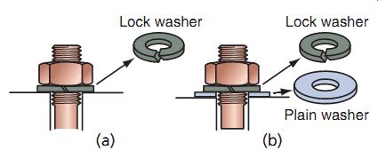
FIG. 21 (a) A typical split-ring-type lock washer. (b) The correct installation
of a plain (or flat) and lock washer. (Parts [a] and [b]:
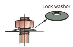
FIG. 22 Cone-type washers must be installed correctly to function properly.
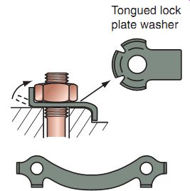
FIG. 23 Tongued lock plate washers can be seen often to hold rotating
components such as sprockets.
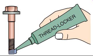
FIG. 24 Thread-locking agents are often used on power equipment engines
to help prevent loosening of fasteners.
Split-Ring-Type Lock Washers
A split-ring-type lock washer (FIG. 21a) is compressed under the pressure exerted by the surface of the nut. The elasticity of the spring and the edges of the ring ends prevent loosening. Applications that include various points on frame- and bolt-incorporating washers are also used. When using with a plain (flat washer) washer, always put the lock washer between the nut and plain washer (FIG. 21b).
Cone-Type Lock Washers--The cone-type lock washer (FIG. 22) is a dished washer made from spring steel. When installed, the center of the washer sits up from the surface. The bearing surface (of the nut) presses on the cone spring washer and the spring reaction presses against the nut to prevent it from loosening. Applications include the clutch lock nut and primary gear lock nut as well as the drive sprocket center bolt.
Tongued Lock Plate Washers--The tongued lock plate (FIG. 23) serves the purpose of a washer and a locking device.
Simply bend the tongue (claw) to the flat face of the nut or into the groove of the nut to lock the nut or bolt head. Applications include clutch locking nuts, some flywheel and starter nuts, and important safety points on the chassis. Replace the lock plate washer with a new one whenever the lock plate is removed.
Thread-Locking Agents and Sealers
Under some conditions, special chemical compounds called thread-locking agents may be needed to help threaded fasteners do their job. Thread-locking agents (FIG. 24) can be used where vibration would cause the fastener to loosen. These compounds are anaerobic adhesives that set up in the absence of air. These products come in several grades, depending on the desired strength, with the most popular being high-strength red and medium-strength blue. Applications include frame components, fork socket bolts, brake disc bolts, and fasteners inside the engine such as the stator coil bolts, bearing retainer bolts, and shift drum stopper plate bolt.
Consider the following when using thread locking agents:
Application of a locking agent increases loosening torque. Take care not to damage the bolt during removal. However, sometimes heat (using a heat gun) is needed to soften the material when higher-strength com pounds are used.
Before applying the locking agent, clean off all oil and/or residual adhesive remaining on the threads and dry them completely.
Applying a small amount of adhesive to the end of the bolt threads distributes the adhesive as it's threaded in.
Excessive adhesive may, during loosening, damage the thread or cause the bolt to be broken.
Locking agents may cause plastic parts to crack.
Some bolts have a locking agent already installed. Never reuse this type of fastener as they're designed to be used only once.
Along with thread-locking agents, thread sealants are used for the same purpose, in locations where the threads of a bolt or another fastener protrude into an area where liquids such a coolant or oil could cause corrosion or leak past the threaded area.
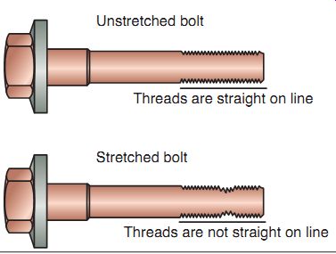
FIG. 25 A stretched bolt (bottom) compared with an unstretched bolt (top).
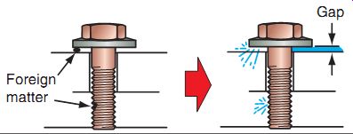
FIG. 26 If debris is in or around a fastener, the latter will not function
properly.
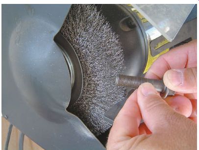
FIG. 27 Cleaning a bolt using a wire wheel.
Use proper safety apparel when using a wire wheel. Can you tell what safety apparel is missing in this picture?
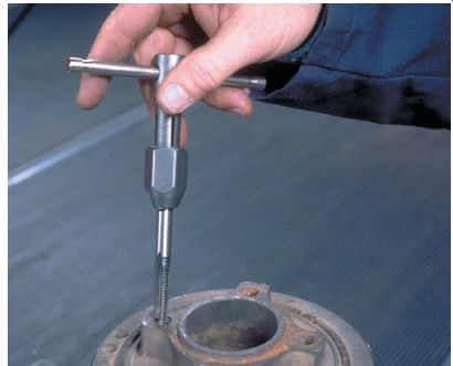
FIG. 28 A technician chasing threads with a tap.
INSPECTION AND CLEANING OF THREADED FASTENERS
Before any reassembly process, threaded fasteners must be inspected, cleaned, and sometimes repaired to be made ready for normal functioning. It's critical to review the service manual specific for the power equipment engine to determine if specific bolts, nuts, or washers can be reused or must be replaced. Failure to replace specific fasteners such as crankshaft-connecting rod bolts/ nuts or cylinder head bolts or nuts, as recommended by the manufacturer, could cause future fastener failure that would be expensive as related components also would certainly be damaged.
Upon inspection of a bolt before use, what is referred to as a stretched bolt may be identified.
If a bolt had been over-tightened, it would have stretched (FIG. 25). A stretched bolt can be identified when a nut threads down the bolt easily but binds when it reaches the stretched area. At that point, it becomes hard to turn. A stretched bolt must be discarded.
Always clean fasteners thoroughly. Installing fasteners with dirt or other foreign matter on the threads or on the bolt- or nut-bearing surfaces will result in improper tension even if the required level of torque is applied (FIG. 26). As the dirt of foreign matter breaks down because of vibration and the attached parts working against each other, the fastener will soon work its way loose.
Solvent cleaning can remove surface grime such as oil and grease. It's necessary sometimes to use a powered wire wheel (FIG. 27) to remove rust and other materials from the head and threads of the fastener. Wear gloves and eye protection when using a powered wire wheel.
Use of a thread die to chase (clean) the threads will insure that the thread is both clean and free of nicks that could cause excessive friction when installed.
Threaded holes in various components must be chased (cleaned) using a thread tap (FIG. 28) to ensure that the internal threads are clean and free of contamination. If damaged threads are found, the threads may be repaired by replacement. Thread replacement will be covered in detail later in this section.
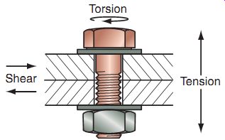
FIG. 29 The forces acting on a threaded fastener.
STRESSES ON THREADED FASTENERS
Preload, as we had discussed earlier in this section, is the tension caused by tightening the fastener that holds the parts together. The forces acting on a threaded fastener are axial tension, torsion, and shear (see FIG. 29). The clamping force is the reaction provided by the bolt on the part mated to it.
Axial tension. The stretching force that is exerted on a bolt when it's tightened into a case or when a nut is tightened onto it. Axial tension is the most important force involved in the tightening of a fastener.
Torsion. The twisting force that is exerted on the head of a bolt when it's tightened.
Shear. The force that is exerted at an angle of 90° to the center line of a bolt.
Clamping force. The force exerted by the bolt holding two parts together.
When a fastener is tightened, an axial tension is applied on it. This stress stretches the fastener and reduces its diameter slightly. As we further tighten the fastener, we reach what is referred to as a yield point (FIG. 30). Continuing to tighten the fastener moves it into the plastic range, in which the fastener stretches permanently, that is, the fastener will not return to its original diameter when the axial tension is removed. If we continue to tighten the fastener beyond its yield point, the fastener reaches its ultimate tensile strength and shortly thereafter breaks.
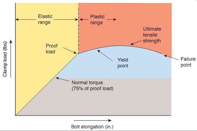
FIG. 30 Different levels of torque that can be exerted on a fastener.
Preload
For any fastener to work properly, it must be stretched sufficiently to produce a static pre load (clamping force) that is greater than the expected external loads. This is what the torque applied to the fastener does. When in their elastic range, bolts and screws stretch like a spring and then return to their original length when tightened. It's critical that the fastener be tightened the right amount. Too little and they will loosen, too much and they may break or dam age threads.
Fasteners tightened into their plastic range will remain permanently stretched and should be replaced. Fortunately, engineers have taken care of these design characteristics. All we need to do is prepare the fasteners correctly and tighten them to the torque specified in the service manual. Preparing fasteners includes inspecting, cleaning, and making sure they're dry.
There are some variables that can affect tightening torque. Tightening torque can decrease over time, from external forces or vibration.
Tightening forces are specified on the basis of fastener strength, strength of fastened parts, and intensity of external forces involved. Tightening must be carried out in accordance with service manual specifications, especially for critical fasteners. For example, tightening a connecting-rod-bearing cap with a torque higher than specified will reduce the oil clearance for the bearing to a value less than specified, which may lead to premature bearing seizure. A low torque,
on the other hand, may loosen the nuts or bearing caps, which may then fall off during engine operation, leading to serious engine damage.
TIPS FOR WORKING WITH THREADED FASTENERS
Here are a few tips when working with threaded fasteners:
Always clean bolts, screws, and threads in engine cases and blow them dry. Dirt or foreign matter under the head or on the threads will prevent a proper torque from being applied, leading to loosening.
Don't lubricate fasteners unless specified in the service manual.
Bolt or screw lengths can vary for engine covers and cases (FIG. 31). These different lengths must be installed at correct locations.
If you're not sure, place the bolts in their holes and compare the exposed lengths. Each should be exposed the same amount. A bolt that is too long will bottom out and break or strip threads. A bolt that is too short will pull the threads out of the case. The exposed length of bolts should be at least 1.5 times their diameter.
To prevent warping important components and ensure proper gasket sealing, torque to multiple-sized fasteners should be applied keeping in mind the following points:
During disassembly, always loosen the small fasteners first.
Tighten all fasteners to hand-tight.
Torque larger fasteners before smaller fasteners.
Torque the bolts in sequence to half the specified torque and then repeat the sequence to the full specified torque to prevent component damage.
If no sequence is given, torque in a crisscross pattern from inner to outer.
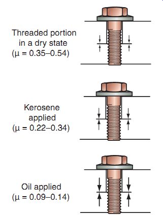
FIG. 32 Dry surfaces have the highest levels of friction, as shown here.
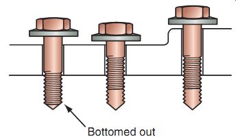
FIG. 31 Use the right bolt lengths when reassembling any component.
TIGHTENING AND TORQUE
As mentioned, the most important point in fastener tightening is the axial tension or tightening force. The problem is that this tightening force is difficult to measure. Using a predetermined tightening torque is, therefore, the most common method of controlling fastener tension. The axial tension is proportional to the torque applied in certain conditions, the most common of which being clean, dry threads.
Friction in the threads uses up 40% of the applied torque. The friction between the bolt head and mating surface uses 50% of the torque.
That leaves 10% to tighten the bolt. Dry surfaces have the highest friction, whereas oiled threads have the lowest (FIG. 32). When a lubricant is applied to fasteners, friction is decreased. µ indicates the coefficient of friction: the lower this number, less the friction.
If the threads are lubricated, more of the torque applied contributes to the axial tension. This means the parts are held together with a greater force and the fastener is stressed more. FIG. 33 gives examples of how much the friction is reduced when kerosene or oil is applied to the threads. With the same tightening torque, axial tension increases greatly with use of a lubricant. This graph can be compared to the images in FIG. 32.
Some manufacturers specify that oil be applied to the threads and the underside of the head of certain fasteners. Such parts must be oiled before tightening. If they're assembled and tightened dry, the requisite preload (clamping force) will not be applied, which could cause the bolt to loosen or a joint to leak. Also of great importance: Don't over oil: excessive oil could cause damage to a part.
All other threaded fasteners must be assembled and tightened dry, because lubrication of these bolts may cause them to break.
Torque
Torque values are determined according to fastener size and strength, and the strength of the parts that are fastened together. In earlier service manuals, a range of torque values was specified. In current service manuals, a single value is given for the torque to be applied.
This is equivalent to the midpoint of the range in earlier manuals. Service manuals specify torque in newton-meters, kilogram-meters, and foot-pounds.
As seen in FIG. 34, torque is simply a force applied to a lever of a specific length. One kilogram attached to the end of a 1-meter arm gives 1 kilogram meter (kg-m) of torque. A weight of 5 kg applied to an arm 1/5 of a meter gives the same torque.
Torque 5 Force 3 Length
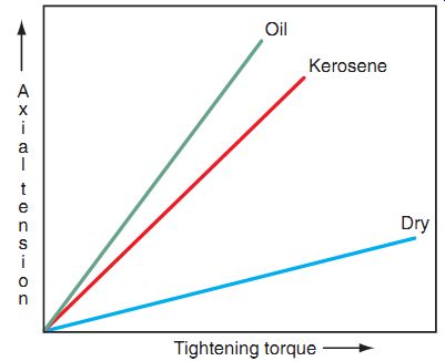
FIG. 33 Different levels of friction when assembly is carried out dry (without lubrication), and when using kerosene and oil.
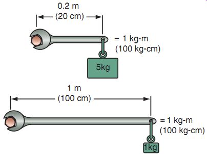
FIG. 34 Torque applied varies with the point of application of torque.
Torque Wrenches
As mentioned in Section 3, there are two common types of torque wrenches used by technicians to tighten fasteners to specifications.
Both will be discussed in more detail here. We will discuss an additional type of torque wrench, the dial torque wrench, though it's not used as often.
Beam-Type Torque Wrench
The beam-type torque wrench (FIG. 35) is the least expensive of the three types mentioned here and works by beam bending in response to the torque applied. It's simple, reliable, and accurate. When tightening a bolt, apply force at the center of the handle. This allows the beam to bend in the manner designed to indicate the correct torque.
Don't over-torque the wrench or the beam may bend permanently.
Rough handling can bend the pointer arm.
However, if bent, it can be bent back to the center without loosing accuracy.
If the beam is bent, it can't be bent back.
Click-Type Torque Wrench--The click-type torque wrench (FIG. 35) is popular with technicians because of its ease of use and easy-to-store profile. It works by preloading a "snap" mechanism with a spring that releases at the specified torque. When the mechanism releases, the ratchet head makes a "click" noise. The torque is set by rotating the micrometer-style handle to the appropriate torque setting. To use, pull on the handle until you feel the handle flex or hear the click.
You'll find the click-type torque wrench easy to use in a confined space because of its ratchet head.
Don't use this torque wrench to loosen tight fasteners as it may damage the calibration mechanism.
When finished, always return the wrench to its lowest setting before putting it away. This will prevent the internal spring from taking a set.
The actual click from a torque wrench is considered a "cycle" of that wrench. Most manufacturers recommend basic calibration after 8,000-12,000 cycles.
Dial Torque Wrench
The dial torque wrench (FIG. 36) isn't as popular as the previous two types mentioned but it's easy to operate. The bezel face can be rotated to "zero" to calibrate the wrench before use. The pointer moves up the scale as the fastener is tightened. Some technicians turn the bezel face to the torque setting and then pull the wrench back to zero to obtain the proper torque.
Ensure "zero" before using the tool.
The glass/plastic bezel cover can break or be scratched; use care when storing the tool.
Calibration should be checked every 12-18 months.
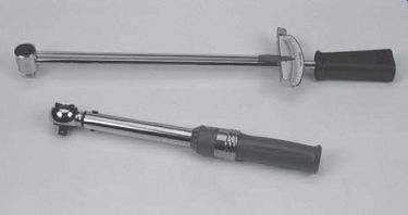
FIG. 35 A beam-type torque wrench (top) and a click-type torque wrench
(bottom).
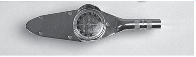
FIG. 36 Dial-type torque wrenches are not used often on power equipment
engines.
Hints for Using Torque Wrenches
To ensure exact accuracy and reliability when using a torque wrench, keep in mind the following points:
Even the most expensive torque wrenches lose accuracy. It's a good idea to have your torque wrench calibrated periodically.
Always work on clean threads. For an accurate torque wrench reading, the final turn of the nut must be tightened with the torque wrench.
Use your torque wrench for tightening only.
Always loosen or remove bolts, nuts, or studs with a standard wrench (not the torque wrench).
If using a dial-type torque wrench, ensure that the dial and pointer are set correctly before applying torque.
Wear proper safety gear when using a torque wrench.
Release the tension on click-type torque wrenches after working with them to keep them calibrated properly.
REPAIRING AND REPLACING BROKEN FASTENERS
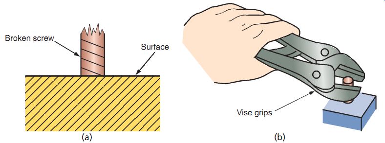
FIG. 37 (a) In most cases, a bolt that has broken off above the surface
can be removed more easily than one that has been broken off flush. (b) Using
a vise grip wrench can be used to remove fasteners that have broken off above
the surface.
Sooner of later, every technician would be required to remove a broken bolt or repair a damaged thread. It may take just a few minutes to repair or it may take hours. It may cost a few cents for a new bolt or screw or hundreds of dollars to repair or replace the component made unusable by a repair job gone bad.
A bolt that has broken off above the surface (FIG. 37a) may be removable with vise grip pliers (FIG. 37b). The following tips will assist you in removing a broken fastener using vise grip pliers:
Tap the top of the broken fastener with a ball peen hammer a few times to loosen or break the grip between the threads.
Applying a penetrating oil to loosen any rust or corrosion may help.
Another technician trick is to heat the surface (with a heat gun or propane torch) to expand the metal and loosen the grip on the broken bolt.
A fastener broken flush with the surface may require the use of screw extractors. Some technicians may try using a sharp punch or chisel to tap the broken fastener counterclockwise to turn it out of the threaded material (FIG. 38). This sometimes works but at times other methods are necessary. Also, using "left hand drills" to drill into the broken fastener may actually remove the bolt as you drill the larger hole.
The drill motor must turn counterclockwise to work properly when using left-handed drill bits; therefore a reversible drill will be needed in these situations.
FIG. 38 Try to remove a broken fastener off flush first by using a sharp punch or chisel and a hammer.
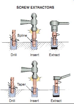
FIG. 39 The two most common extractors.
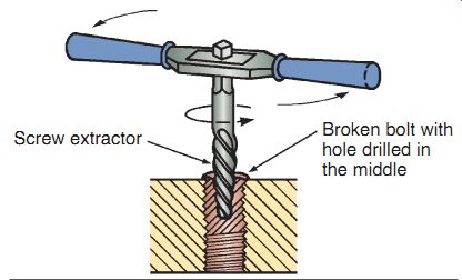
FIG. 40 An easy out screw extractor in use.
Screw Extractors
There are two common types of screw extractors. The easy out screw extractor has large, widely spaced, sharp edges and tapers to a rounded tip. The fluted extractor has multiple, sharp-edged groves along its length and does not have any taper.
Both types of extractors are usually pack aged as kits to be used on different sizes of bro ken bolts, screws, or studs. To remove a broken fastener using an easy out:
Use a center punch to mark the center of the fastener.
Drill a pilot hole all the way through the bottom of the fastener using the smallest drill bit.
Then, drill the hole out using a drill of recommended size for the tool being used.
Insert the easy out by tapping it into place with a hammer, attach the handle, and turn counterclockwise to remove the damaged fastener (Figures 39 and 40).
The fluted extractor set includes several sizes of fluted extractors, the correct-sized drill bits, splined hex nuts, and drill guides. To remove a broken fastener using a fluted extractor, use the same methods as mentioned for the easy out.
Extractors are hardened, which makes them difficult to remove if they break. A broken extractor can't be drilled with a common drill.
Therefore, too much force must not be applied when removing a damaged fastener. If a drill, tap, or easy out does break off (somewhere it's not supposed to be), there are other methods of removal. A process known as EDM (electro discharge machining) can remove the bro ken piece(s). The process is quite expensive and requires the complete disassembly of item to be repaired. The process is like welding, only in
reverse. The results are good but finding a shop in your area that can use this system of fastener removal may be a little tricky.
Drilling and Re-Tapping
Occasionally, after a broken fastener has been removed from a hole with damaged threads, a hole of slightly smaller diameter than the original is drilled. The hole is then carefully tapped back to the original diameter. This method sometimes works and may be well worth the effort.
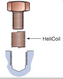
FIG. 41 HeliCoils are used often when thread repair is required.
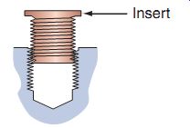
FIG. 42 Solid-threaded inserts are widely used when repairing threads
in a component.
Thread Inserts
When a screw thread is damaged or stripped, a thread insert may be necessary to restore the original thread size. A variety of thread inserts are available. They all involve drilling and tap ping a slightly larger hole. The insert is then threaded and locked into place.
HeliCoil
The HeliCoil is an oversized spring coil made of stainless steel (FIG. 41). HeliCoil kits are available for standard and metric thread sizes.
When installed, the inside thread of the HeliCoil restores the original thread size and pitch and provides a repair that is just as strong and some times even stronger than the original thread.
To install a HeliCoil:
Use the kit drill to drill an oversized hole.
Tap the hole using the tap included with the kit.
Install the insert using the special tool provided with the kit. The insert is installed slightly lower than the surface. A drive tang at the bottom of the HeliCoil locks to the tool during installation. The tang is notched for easy removal once the insert is installed.
Break the driving tang off the bottom of the HeliCoil with a hammer and punch. Remove the tang before installing the bolt.
Solid-Threaded Inserts
In applications that require high strength, such as repairing stripped head bolt/stud holes, solid-threaded inserts are used. The insert shown in FIG. 42 has bottom external threads that are cold rolled. The installation tool locks the insert into place by forcing the bottom threads to expand the mating external threads into the threads cut into mating material (e.g., engines and transmission systems).
Summary
Power equipment engines are held together by hundreds of threaded fasteners.
There are two common systems used to classify the measurement systems used on power equipment engines: the conventional system and the metric system.
Bolts and nuts come in various sizes, grades (strength), and thread types. The four most important bolt dimensions are bolt diameter, bolt head size, bolt length, and the thread pitch.
Quality standards for fasteners are established by the ANSI and the ISO.
A variety of washers serve to achieve the correct load on a bolt and to prevent loosening of threaded fasteners.
Proper tightening of fasteners using a torque wrench is a critical skill required to reassemble components on a power equipment engine.
Torque wrenches used to tighten threaded fasteners vary in accuracy, and for best results, they should be calibrated regularly.
Broken bolts or studs can be difficult to remove or replace. Proper methods must be used to remove broken fasteners.
Thread inserts are used to restore threads in engine or transmission cases and even to replace spark plug threads.
QUIZ
Fill in the blanks in each of the following statements.
1. Power equipment engines use two common measurement systems, the and the ___.
2. ___ is the technical term for the tension caused by tightening the fastener that holds the parts together.
3. The four most critical bolt dimensions are: bolt diameter, bolt head size, bolt length, and ___.
4. The three most common types of threads used on fasteners are ___ , __ , and ___.
5. The of a bolt is determined by the number of threads per inch when using the ___ of measurement.
6. A __ has internal threads and usually a six-sided outer shape.
7. The two common tools used to torque fasteners are the ___ and torque wrenches.
8. During disassembly, always loosen the ___ first.
9. When a screw thread is damaged or stripped, it may be necessary to use a ___ to restore the original thread size.
10. Don't lubricate fasteners unless specified to do so in the ______.