AMAZON multi-meters discounts AMAZON oscilloscope discounts
Goals:
- Identify common hand, power, and special tools
- Know how to select the correct tool for a repair
- Understand advantages and disadvantages of various types of tools
- Identify and select the right measuring tool for different jobs
- Understand the importance of having an up-to-date service information library
INTRODUCTION
Power equipment engine technicians use hundreds of tools to perform a wide variety of repair activities. In addition to the standard hand and power tools that you may already be familiar with, there are specialized and precision repair tools that will probably be new to you. The assortment of tools that you'll use depends primarily on the types of machinery you'll encounter and the specific systems that you'll be responsible for. As an example, if you were to specialize in lawn mowers, your tools would be different from those of someone who specializes in tractors.
Skilled professionals, no matter what their trade or field, know how to use tools correctly and safely. Knowing exactly which tools to use for each task is essential for completing quality repair jobs quickly, safely, and efficiently. When you gain experience in the power equipment engine repair field, you'll acquire the skills to do jobs faster and more efficiently. A large part of this skill development will focus on your ability to use the tools of the trade correctly.
Power equipment engine repair tools can be divided into the following groups:
- Basic hand tools
- Power tools
- Special tools
It would be virtually impossible for us to discuss every type of power equipment engine repair tool in this section. For this reason, we'll limit our discussion to the tools that you'll use most often. You've probably used many of the standard hand tools that we'll cover. But you may be totally unfamiliar with some specialized tools and measuring/testing instruments that we're going to discuss. It's recommended that you take your time as you read about the various tools and instruments and familiarize yourself with their use. Caution: Always wear eye protection when working with tools.
BASIC HAND TOOLS
Basic hand tools are the common tools that are found in just about every workshop toolbox.
Some of these are screwdrivers, hammers, pliers, wrenches, and socket sets. Because they use these tools so frequently, most power equipment engine repair technicians own a complete set of hand tools, similar to the one shown in FIG. 1. Undoubtedly, most of the basic hand tools would be familiar to you.
You've probably used them and may even own many of them. To be sure, however, that you understand the proper use of these tools, we'll take a brief look at each of them. Let's begin with the most commonly used hand tool, the wrench. The largest portion of your current tool collection probably consists of different types of wrenches.
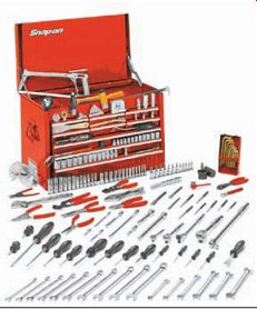
FIG. 1 A typical set of hand tools that a power equipment engine technician
would own. This assortment of tools could be used for different applications
and isn't limited to power equipment engine repair. Snap-on Tools Company.
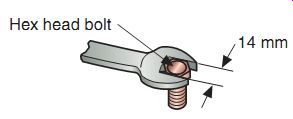
FIG. 2 The size of a wrench is determined by the width of the opening
at the end of the wrench.
Wrenches
Wrenches are used to tighten or loosen nut and-bolt-type fasteners (FIG. 2). As you probably know, wrenches come in a variety of sizes, from very small to very large.
Metric and SAE (Society of Automotive Engineers) are the general classifications of the wrenches found in a power equipment engine technician's toolbox. Metric wrenches use millimeters, such as 10 mm, 11 mm, or 12 mm.
SAE wrenches use fractions of an inch, such as 1/2 inch, 9/16 inch, or 5/8 inch. As a rule of thumb, American-made power equipment engines require SAE tools (keep in mind that this is only a rule of thumb as some American-made engines now use metric components) and foreign-made power equipment engines require metric tools.
More information on different measuring systems will be provided in Section 4.
Wrenches are forged from strong, tempered steel. Each wrench size is designed to fit one particular-sized fastener. A common mis take when using wrenches is to use the wrong size (where the wrench "almost fits"). Using a wrong-sized wrench can, in many cases, damage the fastener and the wrench as well. In addition to varying sizes, wrenches are available in different styles (Figures 3 and 4). The five most common styles are the Open-end wrench Box-end wrench Combination wrench Adjustable wrench Socket wrench Open-End Wrenches
Open-end wrenches have U-shaped openings at both ends and are designed so that the length of each wrench is proportional to the size of its opening. The larger the opening, the longer the wrench's handle, so that more rotational force can be applied. Rotational force is referred to as torque. Caution: Because of the open-end wrench's design, you should never use an extension on a wrench handle to increase the torque.
Using any type of handle extension could break the wrench and possibly cause an injury. There are different types of open-end wrenches. Two common examples are:
The standard wrench (FIG. 5) has a 15° head angle with a different-sized opening on each end.
The l are nut or line wrench (FIG. 6) is used for fuel and oil line fittings or brake lines. The head contacts 270° of the nut for a secure grip while allowing for access around fuel, oil, and brake lines.
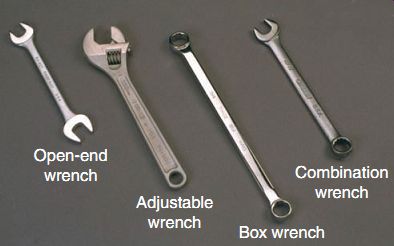
FIG. 3 Four different styles of wrenches.
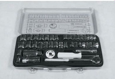
FIG. 4 A typical socket wrench set.
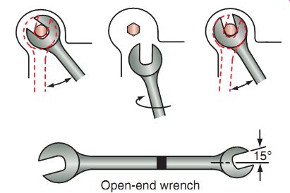
FIG. 5 The standard wrench has a 15° head angle with a different-sized
opening on each end.
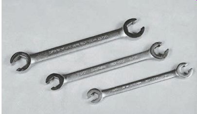
FIG. 6 The l are nut or line wrench is used for fuel, oil, or brake line
fittings. The flare nut wrench head contacts 270° of the nut for a secure grip.
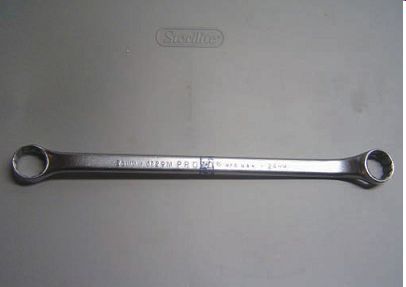
FIG. 7 A typical box-end wrench.
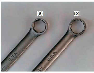
FIG. 8 Box-end wrenches are available with (a) 6-point and (b) 12-point
openings.
When using an open-end wrench, always place it squarely on the nut or bolt and pull toward you. Using this position reduces the chance of injury. Open-end wrenches have a tendency to slip when high torque is applied. If you must use a pushing motion, push with the palm of your hand. Don't grip the wrench with your fingers. You've probably heard the term "knuckle buster." Guess where that phrase came from? And always keep your wrenches clean to help prevent slipping.
Box-End Wrenches
Box-end wrenches (FIG. 7) should be used to loosen very tight bolts or nuts. The end of a box-end wrench encircles a nut or bolt head, providing more contact surface than an open-end wrench. Box-end wrenches have thin heads. This makes box-end wrenches useful in tight places, where there's limited access space around the nut or bolt head.
Box-end wrenches are available with 6-point and 12-point openings (FIG. 8). The number of points refers to the inside shape of the box end. A 6-point box-end wrench provides more support to the head of a bolt than the 12-point box-end wrench.
You should use a 6-point wrench on bolts and nuts that are very tight. The 6-point wrench is less likely to slip than a 12-point wrench. The main disadvantage of the 6-point wrench is that its head is thicker than that of a 12-point wrench. Also, a 6-point wrench can be placed on a bolt or nut in only six different positions.
Because its head is thinner and can be placed on the bolt or nut in 12 different positions, the 12-point style wrench is the better choice to use in tight places. You frequently can't get enough wrench travel in tight places to advance a 6-point wrench to the next turning position. With a 12-point wrench, the travel required to turn to the wrench to the next position is only half that required for the 6-point wrench. Remember, a 6-point box-end wrench is stronger and grips the fastener more securely, whereas a 12-point usually works better in tight spaces.
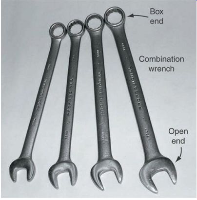
FIG. 9 Combination wrenches are among the most popular wrenches found
in a power equipment engine technician's toolbox.
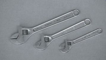
FIG. 10 Adjustable wrenches are commonly called crescent wrenches and
have movable jaws that allow you to adjust the opening to fit a nut or a bolt
of almost any size.
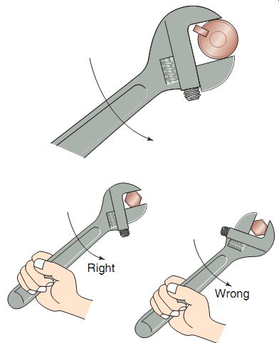
FIG. 11 Proper use of an adjustable wrench.
Combination Wrenches
Combination wrenches (FIG. 9) combine the open-end wrench and the box-end wrench into one tool. In most cases, both ends of the combination wrench are of the same size. This allows you to use the box end to loosen bolts or nuts that are tight and the open end to quickly remove them when they're loose.
Adjustable Wrenches
Adjustable wrenches (also called crescent wrenches) have movable jaws that allow you to adjust the opening to fit almost any size nut or bolt (FIG. 10). But adjustable wrenches don't grip the fastener as tightly as other types of wrenches.
Adjustable wrenches have a tendency to slip and round off the corners of nuts and bolt heads. Because of this limitation, adjustable wrenches should be used to remove only bolts or nuts that are already loosened. Adjustable wrenches can be used in a pinch, when the correct size of wrench isn't available. Remember that adjustable wrenches can slip. When using them, always pull toward you to save your knuckles, by using the method shown in FIG. 11.
Note that there is a right and wrong way to use the adjustable wrench and using it incorrectly can cause the wrench to break.
Socket Wrenches
Socket wrenches are among the more frequently used tools and are usually purchased in sets (FIG. 12). The individual sockets contained in a set are in graduated sizes. The size of the socket refers to the size of the bolt head or nut that the socket fits. Socket sizes range from small to very large, to match the largest avail able bolt and nut sizes.
There are two basic depths of sockets: standard and deep well (FIG. 13). Deep well sockets allow access to recessed fasteners or nuts that are threaded onto studs.
Sockets are available in 6- and 12-point configurations, just like box-end and combination wrenches (FIG. 14). The 6-point socket is stronger. The 12-point is good for tight areas but is more likely to round off the nut or bolt. Some sockets have fluted corners designed to place stress on the sides of the fastener. Sockets of this design tolerate higher torque with less chance of rounding off the nuts or bolt heads.
Sockets come in various degrees of hardness.
The strongest are made for use with impact drivers and are usually black in color. Hand type sockets are usually chrome plated and are not meant to be used with hand, air, or electric impact drivers (FIG. 15).
Sockets can be installed onto different types of handles (FIG. 16). The drive lug on the socket handle fits into the drive hole in the socket. Sockets come with different drive hole sizes: typically 1/4 inch, 3/8 inch, and 1/2 inch.
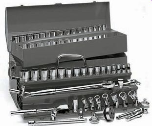
FIG. 12 A wide range of different types of sockets.
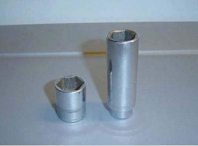
FIG. 13 A standard socket (left) and a deep well socket (right).
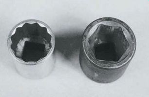
FIG. 14 Six- and 12-point sockets. Whenever possible, it's recommended
that a 6-point socket be used as it's stronger.
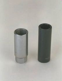
FIG. 15 You can easily tell the difference between hand and impact sockets.
The impact socket is black in color and the hand socket is chrome plated.
The most common handle is the reversible ratchet handle. A lever on the handle allows you to change direction to either tighten or loosen fasteners (FIG. 17). Reversible ratchet handles are great for removing and installing fasteners quickly, but they can be damaged if too much torque is placed on them. Ratchet handles can have a swivel or flex head to allow easier access to difficult to reach fasteners.
If you're using a socket to loosen an exceptionally tight fastener, use a breaker bar, not a ratchet handle, to turn the socket. A breaker bar is a non-ratchet solid handle with a socket drive fixed on its end. Because a breaker bar has no ratchet mechanism, it can withstand much more torque than a ratchet handle.
Along with the breaker bar, other popular handles are speed handles and sliding T-handles (FIG. 18). These handles are often used to turn sockets in tight spaces. Most socket sets also contain a variety of extension bars and adapters. These accessories allow the sockets to be used in different situations.
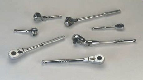
FIG. 16 Different styles and sizes of ratchet handles for socket wrenches.
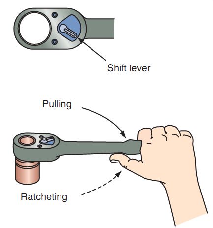
FIG. 17 A reversible ratchet handle. Note that it has a shift lever that
is used to change the direction of the ratchet action.
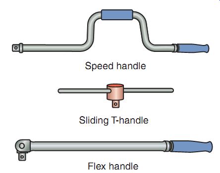
FIG. 18 Popular types of socket drivers.

FIG. 19 An Allen and a Torx wrench.
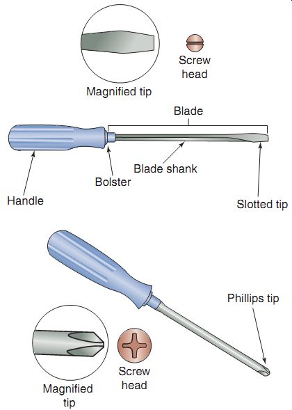
FIG. 20 The basic parts of a screwdriver.
Allen and Torx Wrenches
The Allen wrench or hex wrench is a short, six-sided rod that is used to tighten screws and bolts that contain similar six-sided (hex) indentations (FIG. 19). A typical Allen wrench has a right-angle bend near one end. The bend forms a convenient handle. Certain special Allen wrenches are equipped with T-handles or screw driver-style handles, and others are designed to be used with socket wrench drive handles. Allen wrenches can be purchased individually, but they're normally sold in sets that contain all the commonly used sizes.
The Torx wrench is similar to the Allen wrench, except the end of the Torx wrench is star-shaped (FIG. 19). Because they can handle more torque without slipping or strip ping, Torx wrenches and bolts are used where higher fastening strengths are required. Torx bolts are ideally suited for use with impact tools. Torx wrenches are also available with
screwdriver-type handles or attachable to socket wrench drive handles.
Screwdrivers
Although just about everyone is familiar with the standard screwdriver (FIG. 20), let's have a quick review. A standard screwdriver has the following parts:
A handle, which is usually made out of plastic or wood A blade shank, which can be round, square, or hex. If it's square or hex, you can use a wrench on the screwdriver to increase torque.
A bolster, which some screwdrivers have, allows you to use a wrench A tip or blade, which you insert into the screw head slot, which is commonly a straight tip or Phillips head The screwdriver is one of the most abused hand tools. Have you ever:
Used a screwdriver as a pry bar or chisel? Used a screwdriver handle as a hammer? Hammered directly on a screwdriver handle? Used the wrong-sized screwdriver? Used the wrong type of screwdriver?
See what I mean?
There are so many opportunities to misuse screwdrivers. Almost every one of us has done one or more of these things at one time or another. If used improperly, the screwdriver can cause damage, even serious injuries to you.
Types of Screwdrivers
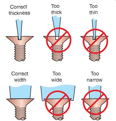
FIG. 21 The blade of a screwdriver should fit the screw slot snugly to
prevent slipping or slot damage.
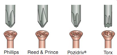
FIG. 22 These screw head shapes are used in many applications on power
equipment engines.
Screwdrivers are available in a variety of shaft lengths and tips. Here are the most common:
Flat (or slot) tips. These range in size from very small (1/16 inch wide) to large (3/4 inch or wider). Be sure to always choose a screw driver of correct thickness and width, as required by the fastener (FIG. 21).
Phillips screwdriver tips. (FIG. 22) These have a crossed point but a somewhat blunt end. These tips have good holding power and are less likely to slip than slotted tips. The common sizes of Phillips screw head slots used in power equipment engines work are #1, #2, and #3.
Reed & Prince tips. These tips are similar to Phillips tips but have a sharper tip. Reed & Prince tips are not interchangeable with Phillips-tipped screwdrivers.
Pozidriv tips. These are similar to the Phillips tips but allow for a more positive fit of the tool, which in effect allows more torque to be applied. Pozidriv screws can easily be distinguished from other tips, by a line embossed on the screw head at 45° to the slots.
Torx tips. This type of tip is used when higher fastening strengths are required, because Torx tips can handle more turning force without slipping.
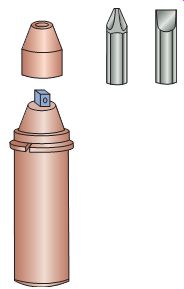
FIG. 23 A typical impact screwdriver. Note the removable cap that would
allow a socket wrench to fit on the end of the tool.
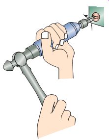
FIG. 24 Recommended grip when using an impact screwdriver.
Special Purpose Screwdrivers
Screwdrivers are also available in special shapes to provide access in restricted areas.
Several of the special-shaped screwdrivers are described here.
Offset screwdrivers. These are special-purpose tools with an angled tip to allow access where space is limited. The offset screwdriver comes with either slotted or Phillips tips and is avail able in different sizes.
Stubby screwdrivers. These have a short shaft and a short, fat handle. Like the offset style, the "stubby" is used in cases where there's limited access space. The stubby screwdriver is available with either slotted or Phillips tips.
Angled or remote screwdrivers. These have a hollow tube with a handle on one end and a bit on the other end. They're used for jobs where you can't get hand access. Some are curved or angled. Deluxe versions may have a 1/4-inch square drive end to accommodate interchangeable tips.
Impact screwdrivers. These are used often on power equipment engines to remove and install fasteners where hand or wrench torque is insufficient (FIG. 23). The drive mechanism of the impact screwdriver converts the impact force of a hammer blow to rotational torque, which is transferred to the screwdriver tip.
The end of the impact screwdriver is designed to accept a variety of tips. When using the impact screwdriver, always:
Use the correct size bit. Use a bit that was designed for impact use. Use eye protection equipment. To use the impact screwdriver, first install the tip onto the fastener and twist the tool in the desired direction. Hold the tool firmly and keep the tip squarely on the fastener; then strike the tool sharply with a hammer (FIG. 24).
Observe the following rules when you're using any screwdriver:
Always clean the slot(s) in a screw head before attempting to remove the screw.
Always hold a screwdriver so the shaft is at a 90° angle to the screw slot. Don't hold it at an off angle as the screwdriver may slip out of the screw and may damage the screw.
Make sure that the screwdriver blade fits a screw slot snugly to prevent slipping and possible damage to the screw and/or screwdriver.
Never use a screwdriver to cut or remove metal, punch holes, pry, or for any other unintended purpose. This could damage the tool and cause injury.
Never hammer on the handle of the screwdriver (except, of course, for impact screwdrivers).
Never use a screwdriver to work on an object that you're holding in your hand.
The screwdriver could slip and cause a painful injury. Use a bench vise to support the object that you're working on.
Pliers
Pliers are another commonly used hand tool. There are a variety of pliers (FIG. 25). They vary in size and shape, depending on their intended function. Certain pliers are designed for holding or gripping, others are designed for shaping, and others are used for cutting.
Types of Pliers
Combination and rib-joint pliers. Also known as slip joint pliers, these are used generally to hold parts when you work on them or to twist and bend materials. Rib-joint pliers have a slip joint that lets you open the jaws wide to grip large-diameter items. The jaws have gripping teeth. The outside end of the jaw set is for grasping flat objects and the middle for grasping curved objects.
Locking or "vise grip" pliers. These are functionally similar to combination and rib-joint pliers. Locking pliers are used to get a firm holding grip on items. They can be locked in place to hold parts tightly while keeping both your hands free. They can function as a small, portable vise. For example, you can use locking pliers to hold two metal parts in position while you install screws, washers, or bolts.
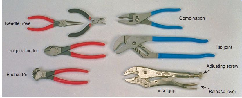
FIG. 25 A wide variety of pliers are available; shown are just a few that
would typically be found in a power equipment engine technician's collection.
Needle nose pliers. These are useful for grip ping or twisting small parts and for reaching parts in limited-access spaces. The jaws of needle nose pliers are smaller and thinner than those of long nose pliers. Needle nose pliers allow you to easily move and position parts that are too small to be handled properly with your fingers. Use of these pliers for heavy work can easily damage them. The tips of the jaws will break if you apply too much pressure on them. Needle nose pliers are often found with bent jaws to help get to tight spaces.
Cutting pliers. These come in different shapes and sizes, with the most popular being diagonal and the end cutter designs.
Retaining-ring pliers. These (FIG. 26) are used to spread or compress retaining rings when these rings are being removed or installed. There are two main types of retaining-ring pliers: those used for internal retaining rings and those used for external retaining rings. These pliers are of generally either long nose type or angle nose type to allow for varying access angles. Some models of retaining-ring pliers come with replacement tips. External retaining rings fit into grooves machined in the outer surfaces of shafts. Internal snap rings are used to retain components on the inside of hollow shafts.
Special Purpose Pliers
The following types of pliers are also often used when working on power equipment engines.
Hose clamp pliers. These have grooves cut into the jaws to provide positive gripping when removing or installing wire hose clamps.
Wire stripper/crimper pliers. Commonly referred to as electrical pliers (FIG. 27), these are used to remove insulation from wire and install crimp-type electrical connectors.
Snips or shears are used for cutting sheet metal and metal gasket material. They come in several styles and sizes to match the material being cut. Aviation snips are used for cut ting sheet metal and come in left, right, and straight cutting styles.
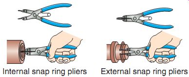
FIG. 26 Internal and external retaining ring pliers in use.
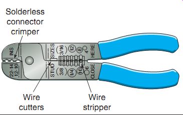
FIG. 27 Wire stripper/crimper pliers, also known as electrical pliers.
Hammers
Power equipment engine technicians use a wide variety of hammers, which range in size from 2 to 48 ounces (FIG. 28). Ball peen and mallet (or soft-faced) hammers (FIG. 29) are two of the most common types.
The head of a ball peen hammer has two opposing striking surfaces, a flat-faced surface and a rounded surface. The flat-faced surface is used for regular hammering. The ball end is used primarily for shaping cold metal.
You should use a mallet or soft-faced hammer if a ball peen hammer might damage the part that you're working on. Several types of soft-faced hammers are commonly used in a power equipment engine repair shop.
Rubber hammers. These are used to help seat tire beads and to carry out sheet metal work. If you're concerned about damaging a part, use a plastic-faced hammer.
Plastic-faced hammers. These are available with replaceable heads of varying densities (hardness). Almost all dead blow hammers are made out of high-impact plastic. The plastic shell is filled with lead shot that helps direct the force from the hammer blow and prevents the hammer from bouncing on impact. They're frequently used where a heavy, non-damaging blow is needed, such as while installing a bearing.
Brass/bronze hammers. These hammers are soft faced and prevent damage to the part and sparks when using them.
Here are a few things to remember when using a hammer:
Make sure that the head is securely attached to the handle.
Wooden hammer handles should be replaced if damaged. Be sure that the handle fits the hammerhead securely. The handle requires the correct-sized wedge to properly retain the head.
You can't repair fiberglass or steel hammer handles. Replace the hammer if the head becomes loose or damaged or if the handle is cracked.
Grip the hammer close to the end of the handle to provide better control of the tool and strike a stronger blow.
Always ensure that while striking, the hammer face is parallel to the object being hit.
Always wear safety goggles to protect your eyes.
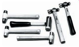
FIG. 28 Types of hammers.
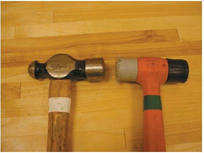
FIG. 29 The ball peen hammer (left) and rubber mallet (right) are among
the most commonly found in a power equipment engine technician's toolbox.
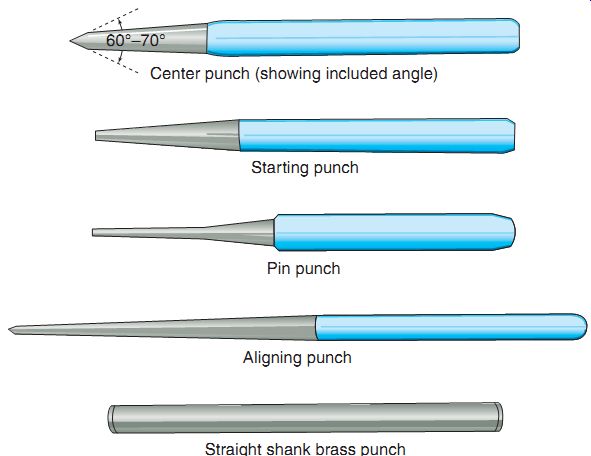
FIG. 30 Punches used in power equipment engine repair.
Punches and Chisels
You'll use an assortment of punches and chisels when working on power equipment engines (FIG. 30). Punches are used for aligning and driving items, whereas chisels are used for cutting.
Punches
Center punches. These have tempered ends with sharp points. They're used for punching indentation marks on metal. These marks are used as reference points for measuring or as starting points for drilling.
Starting or aligning punches. These have tapered shafts with flat tips. They're used to align holes or to start pins moving.
Pin and straight shank punches. These have no taper. They have a flat tip and are used to drive out pins. If you use the correct-sized drift punch, you won't enlarge the hole and damage the end of the pin.
Here are a few points to remember when using a punch:
Hold the punch with a firm--but not overly tight grip.
Use a punch holder when possible to prevent possible injury to your hand (if the hammer misses the punch when striking).
Hold the pointed end of the punch in place while striking the other end with a ball peen hammer.
Strike the end of the punch squarely.
Always wear approved eye protection equipment when using punches.
The ends of punches wear or get misshapen with use. When the end surface enlarges beyond its normal size or mushrooms, you should grind the bit end back to its original shape.
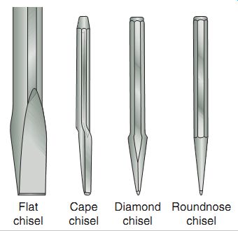
FIG. 31 Different types of chisels.

FIG. 32 The bench vise is a useful holding device that mounts onto a table
edge. Note that the jaws are covered with a soft metal insert to protect the
item being held.
Chisels
Chisels (FIG. 31) are another of those often abused tools. They're not meant for opening paint cans, tightening or loosening screws, or prying things apart. Unfortunately, many a chisel has met an early end because of its use for one of these unintended functions! Chisels are meant to be used for cutting, shearing, and chipping.
The flat chisel is the most common type of chisel used in a power equipment engine repair shop. The chisel has a bevel on both sides of the cutting edge. Like the punches that we just covered, the striking head on the chisel is softer than the cutting edge.
Here are a few things to remember when using a chisel:
The chisel head diameter should be approximately one half the diameter of the hammer head that you use for striking the chisel.
Hold the chisel the same way you would hold a punch. Don't hold it too tightly, but use a firm grip.
Chisels wear with use. You should grind the head when it shows signs of mushrooming.
Always keep the cutting edges of chisels sharp.
Grind the cutting edges to the original contours and angles.
Always wear eye protection.
Use a chisel holder when possible to prevent possible injury to your hand (if the hammer misses the chisel when striking).
Clamps and Vises
Clamps and vises are used to hold workpieces securely. This frees up both your hands so that you're better able to handle tools. Clamps and vises are often referred to as an extra pair of hands. Proper and timely use of a vise or clamp can help prevent injuries and eliminate damage to expensive parts and components. If you're ever in doubt as to whether or not you should use a vise, use it! It only takes one slip or accident to make you wish you did.
C-clamps are basically portable vises that you can use to hold pieces of material together while you work on them. They're available in a variety of sizes, to accommodate a wide range of applications. Most power equipment engine repair shops have a collection of C-clamps, with multiples of each size.
The bench vise (FIG. 32) is a useful holding device that clamps onto a workbench or table edge. The jaws of a vise are opened and closed by turning a handle. The jaws are usually covered with soft metal. This covering protects the piece being held in the vise from scratches and dents. There are also jaw protectors made of soft materials to better protect items placed in a vise.
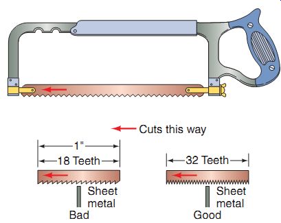
FIG. 33 A standard hacksaw with two types of blades. A thin material requires
more saw teeth, as seen in the example here.
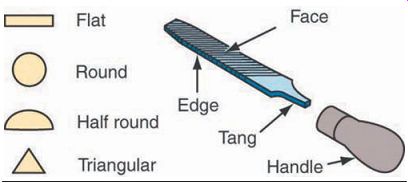
FIG. 34 The parts of a file and the different edge shapes used by a power
equipment engine technician.
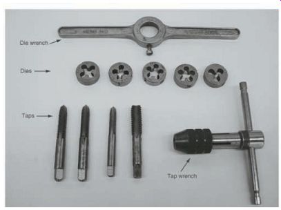
FIG. 35 Taps and dies are used to cut threads.
Cutting Tools
Various types of cutting tools will be found in a power equipment engine service shop. The most common are covered here.
Hacksaws
Hacksaws are used to cut metal stock that's too heavy to be cut with snips or cutting pliers (FIG. 33). Hacksaws are available with adjustable frames to accommodate different length blades. A wing nut on the blade retention bracket is used to tighten the blade to the correct tension. An improperly tensioned blade doesn't cut well and dulls quickly. Hacksaw blades are available in a variety of lengths, hardnesses, and tooth patterns for cutting different materials.
Generally speaking, harder and thicker materials require coarser, harder hacksaw blades.
When using a hacksaw, it's important to apply pressure only on the forward stroke. Use little to no pressure on the backstroke.
Files--Files are cutting tools used to smooth
surfaces and edges. Files are classified by their cross- sectional shapes and types of teeth (Figure 34). The main parts of the file are the face, edge, and tang.
Taps and Dies
Taps and dies (FIG. 35) are used to cut threads in metal stock. A tap cuts "female" threads (equivalent to the threads in a nut). A die cuts "male" threads (like the threads on a screw or bolt). There are different types of taps for various uses. A popular tap used on power equipment engines is the bottoming tap, which allows material to be removed (i.e., "threaded") down to the very bottom of the hole. The tap is turned using a special wrench called a tap wrench. Dies are turned using a die wrench.
Here's a quick overview for using taps and dies. To use a tap, insert the proper-sized tap into a predrilled hole in the metal stock. Screw in the tap about a third of a turn and then back (to break the excess material from the newly cut thread) until the hole is threaded. To use the die, clamp the bolt or screw stock into a vise, and screw down the die using a back-and-forth motion to cut the threads (FIG. 36). Note that the actual use of these tools is complex, precision work that requires skill and experience.
We've simplified the description so that you can distinguish between using a tap and using a die.
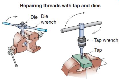
FIG. 36 Use of a tap and die to repair threads in different types of fasteners.
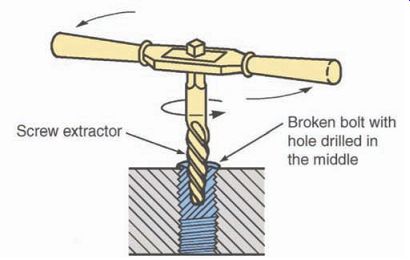
FIG. 37 A screw extractor is a handy tool to assist in the removal of
broken fasteners.
Screw Extractors
The screw extractor (FIG. 37) falls under the cutting area and is a valuable tool that's similar in operation to the tap and die. If a bolt or screw head has been accidentally sheared off, you can use a screw extractor to remove the screw. To use a screw extractor, start by drilling a small hole in the center of the broken screw.
Then thread the screw extractor into the hole and twist it in a counterclockwise direction.
The screw extractor self-taps into the broken screw. Continue turning in the counterclockwise direction and the broken screw or bolt will be extracted.
POWER TOOLS
Power tools are essential to the power equipment engine technician. Proper use of power tools will help to make you more efficient at your job. You must, however, exercise extreme care when using power tools. Not only can they cause severe injuries (covered in Section 2), they can also break fasteners, warp covers, and strip threads and permanently damage components. The power-operated hand tools that we'll cover are either driven by air pressure or powered by electricity.
Drills
One of the more common power tools is the drill. A power drill, sometimes referred to as a drill motor, is a handheld device that's used to drive a drill bit.
The drill bit is a tool that bores through the material. The end of the bit that attaches to the power drill is the shank, and the power drill's socket that holds the drill bit is the chuck.
Power drills come in a variety of speeds. Speed is measured in rpm (revolutions per minute). You should consider rpm values before selecting a drill. Lower-speed drives are well suited for drilling large holes in certain types of metal. Higher-speed drives are better for drilling smaller holes. Drills with lower rpm values are often equipped with gripping handles. These handles are necessary because of the high rotational torque produced by these tools.
Some drills are equipped with variable-speed motors that are controlled by movable triggers.
These variable-speed drills are handy for day-to day use. Many drills also have a reverse feature that allows you to back a drill bit out of the material you're drilling.
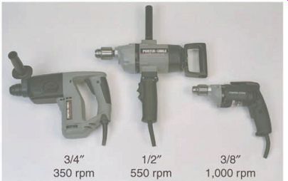
FIG. 38 Different types of drill motors. The most common drill found in
a power equipment engine technician's tool collection is the 3/8-inch drill.
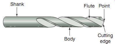
FIG. 39 The parts of a typical drill bit.
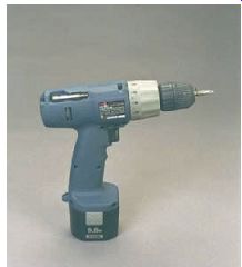
FIG. 40 Self-powered drill motors are popular and can also be used as
a powered screw driver, as seen here.
Power drills come in two common shop sizes: 1/2 and 3/8 inch (FIG. 38). These measurements refer to the maximum diameter of the drill bit shank that the chuck will accept. The larger 1/2-inch power drill is used for special low-speed, high-torque situations. The 3/8-inch drill is more commonly used for general-purpose applications in the shop. 3/4 inch drills are not as common in power equipment engine repair shops but are available for drilling larger holes.
Drill bits (FIG. 39) are manufactured from hardened steel rod stock and are available in a variety of shapes and lengths. They're frequently sold in graduated-size sets, but each size is available separately.
Drill bits are available in both SAE and metric sizes. A well-equipped repair shop has at least one complete set of each. The drill bits used in a handheld power drill are the same as those used in a shop-style drill press. You must consider the type and thickness of the material you'll be drilling and the type and size of the power drill you'll be using when making a drill bit selection.
Not all bits are made for cutting metal. Some are made for wood, plastics, and concrete.
Here's a safety tip when drilling metal. When the bit starts to break through the other side of the metal, the bit may catch and twist the power drill. That's why you should be sure that the piece you're drilling is properly secured and you have a firm grip on the power drill. This will help avoid damaging the part or the drill and will reduce the risk of injury.
Rechargeable cordless drills are popular (FIG. 40). These drills are quite powerful and allow you to work in difficult places with out being restrained by an electrical power cord.
This is particularly handy if you have to work in a remote location where normal power isn't available. Rechargeable batteries are the power source for cordless drills. A fully charged battery may provide several hours of drill usage. Because they must be recharged periodically, you may want to keep spare batteries handy. That way, when you're busy, the only time you'll lose is the time it takes to swap batteries. Be sure to read the instruction manual for proper use and maintenance of these batteries. Some types should be used until they're completely discharged, and other types may be recharged at any time during use. If you recharge the first type before it's completely discharged, the battery's quality will be compromised and its useful life shortened.
Always be cautious when using power drills.
Be sure to follow these guidelines:
If you're using corded drills, use only grounded power equipment.
Determine if there are any obstructions or wiring in the path of the bit before drilling.
Select the correct drill-and-bit combination to perform the drilling task effectively and safely.
Don't apply too much pressure on the drill bit.
Use bit lubricants where required.
Ensure that the bit is tightly clamped in the chuck.
Never leave the chuck key in the chuck.
Use sharp bits. A dull bit could bind, causing the drill to grab. An unexpected twist of the drill could injure your wrist.
To drill a large hole, start by drilling a smaller hole and gradually increase the hole size by selecting increasingly larger bits.
Drill Press
Another power tool you may need from time to time is the drill press. The drill press is a large, floor-standing device that can drill precisely located and angled holes. Because the drill press holds the drill bit in an exact position, it can cut at precision angles and depths. Drill presses use many of the same drill bits that are used with the handheld power drill.
Bench Grinder
The bench grinder is another useful tool in the power equipment engine service department.
The typical bench grinder (FIG. 41) has two rotating wheels, one with an abrasive grinding surface and the other with a buffing wire surface.
The wheels can be used to sharpen tools, buff or polish metal, and remove rust from parts. Also popular are handheld grinders, which are more flexible to use as they're not stationary tools.
It can't be overstated that caution should be used every time you use any type of grinder.
Always use eye protection equipment and heavy gloves. Gloves will protect your hands from the heat caused by grinding and abrasives. Always keep a firm grip on the piece you're grinding or buffing. Finally, make sure that all guards, guides, and shields are in place before you operate a grinder.
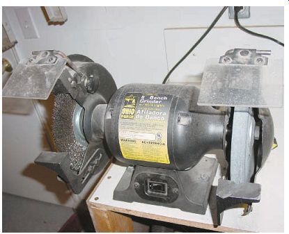
FIG. 41 A typical bench grinder has a grinding wheel as well as a wire
brush attachment.
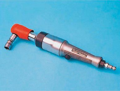
FIG. 42 An air ratchet can aid in the speed of removal of fasteners, but
should not be used to tighten fasteners.
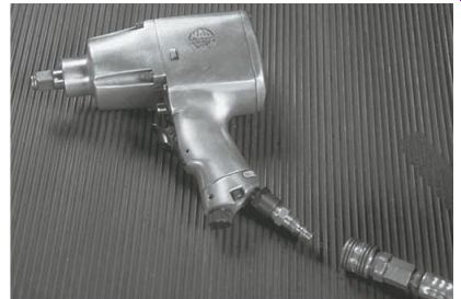
FIG. 43 A typical air-power impact wrench.
These types of tools should be used only to remove items and not used to install, as they're so powerful that they could break or over torque the fastener in question.
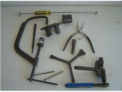
FIG. 44 An assortment of special tools used in power equipment engine
repair.
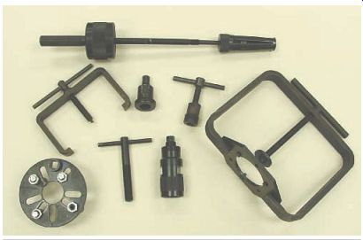
FIG. 45 Different types of pullers related to power equipment engines.
Air Tools
The air ratchet (FIG. 42) is similar to the standard hand ratchet wrench but is larger than the hand ratchet. The size of the air ratchet drive restricts the places where it can be used directly. With a selected set of shaft extensions and universal joint couplers, the air ratchet can be used for most applications. There are 1/4-inch and 3/8-inch drive lug models. The air ratchet turns at a much higher speed than a handheld ratchet and lets you remove nuts and bolts more quickly.
Power impact wrenches are driven by com pressed air. They come in either 3/8-inch or 1/2-inch sizes (FIG. 43). Power impact wrenches are useful for component disassembly but aren't recommended for reassembly.
Caution: It's easy to apply too much torque using a power impact wrench, which could easily shear the fastener and/or damage the part or assembly that you're working on.
As mentioned earlier, special, heavy-duty impact sockets are designed for use with air or impact wrenches. If you recall, they're the ones that generally have a black finish. Here's a handy hint: never start a bolt or nut with a power impact wrench. The fasteners can cross thread, causing damage to the fastener or component. Remember to always use approved eye protection equipment when using power tools.
When using compressed-air power tools, never exceed the recommended air pressure rating of the tools.
SPECIAL TOOLS
The basic hand tools that we described are often used to repair power equipment engines. But many repair activities involve procedures that can't be performed with standard tools alone.
You'll need various special tools (FIG. 44), especially when rebuilding engines. As you learn more about power equipment engine repair, you'll discover that there exists a special tool for almost every purpose.
You should be aware that some special tools are designed to be used on only one make or model of engine, whereas other special tools can be used on a variety of engines. In most cases, these special tools are owned by the service department and controlled by the service manager, but many technicians opt to purchase all the special tools that they utilize, to ensure that they know that they have the right tool at hand whenever they're in need of it. We'll review the names and uses of some special power equipment engine repair tools now. You're not expected to understand how to use these tools yet; you're expected just to become somewhat familiar with them. In later sections, we'll cover the use of specialized tools in detail. Now, let's take a look at some more common special tools.
Pullers--Pullers are used to safely remove gears, fly wheels, or various such components from shafts. A puller can easily separate machined parts that are tightly pressed together without damaging the parts. There are different types of pullers used in power equipment engine repair (FIG. 45). For safety reasons and protection of precision parts, you should use pullers whenever possible. A type of puller called a bearing splitter is popular as it features knife like edges that are easily placed behind the part to be removed to secure a gripping surface when clearances are limited.
Precision Measuring Tools
Precision measuring tools are used to make exact measurements of parts or distances between parts. Measuring tools are used primarily to check for wear of components and specific, part-to-part clearances when reconditioning or rebuilding an engine. The measuring instruments used during power equipment engine repair can range from standard rulers to precision instruments. They're designed to measure thickness, clearances, pressure, and fastener tightness. Let's take a quick look at some of the common measuring tools.
Vernier Calipers
The vernier caliper is one of the most commonly used precision measuring tools in power equipment engine repair work (FIG. 46). They can be used to measure inside, outside, or depth measurements, which makes them versatile.
To operate vernier calipers, place the jaws of the caliper around the part (FIG. 47). The caliper indicates the size of the object on its display scales. You can use the jaws of most sliding calipers to measure both outside and inside dimensions.
Individual styles of vernier calipers display their measurements differently. Some of the more common styles include the printed beam and vernier scale, the dial gauge, and the digital display to allow quick readings. Our caliper example has a printed beam and vernier scale.
You must read the numbers on the scale and perform minor calculations to obtain the actual measurement.
In contrast, digital calipers (FIG. 48) are considered by many to be much easier to use. The caliper displays the true measurement directly on the digital display screen and most will show in SAE or metric measuring systems.
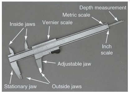
FIG. 46 The vernier caliper is a versatile tool that can be used to measure
inside and outside diameters as well as depth.
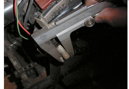
FIG. 47 A vernier scale caliper is shown being used here.
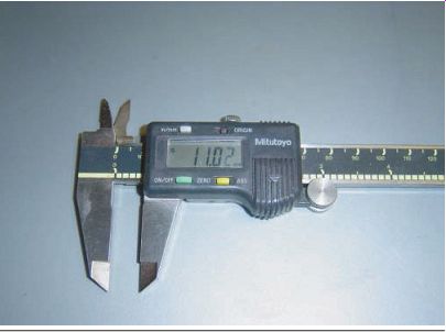
FIG. 48 Some people feel that reading a digital caliper is easier than
reading the standard vernier scale. As you can see here, that point is hard
to argue!
Micrometer
As mentioned, vernier calipers can be quite accurate, but they're less accurate than micrometers. In those cases when exact precision is needed, micrometers should be used.
The micrometer is used to measure the size of a part or component. The basic components of a micrometer are shown in FIG. 49.
Micrometers come in a variety of sizes and styles (FIG. 50a). Some micrometers are designed to measure the outer dimensions of an object, whereas others are made to measure inner dimensions, such as the inside diameter of a cylinder. Another type of micrometer measures depth. Many micrometers use an electronic read out that allows quick and easy-to-read measurements, whereas many other micrometers can be read using a vernier scale on the tool itself. Just like vernier calipers, micrometers with digital displays can be purchased, which also allow for easy conversion from SAE to metric denominations (FIG. 50b).
To use a micrometer, place the object between the anvil and the spindle, and then turn the thimble until the anvil and spindle contact the object with a light resistance. You can read the measurement on the thimble and sleeve of the gauge (FIG. 51).
Micrometers are often used during the engine-rebuilding process. During a rebuild, you'll completely disassemble an engine and inspect and measure all the engine parts to determine if they're worn or damaged. Because the micrometer can measure thickness so accurately, it can easily detect small changes in part sizes, which indicates wear. Using a micrometer is a typical procedure performed during engine reconditioning.
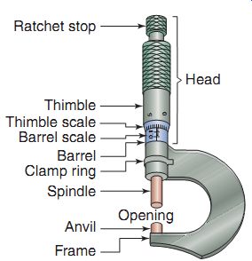
FIG. 49 The components of a typical micrometer.
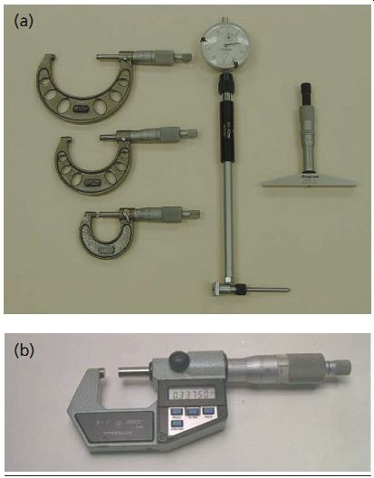
FIG. 50 (a) The three primary types of micrometers used in power equipment
engine repair. (b) Just like the vernier caliper, micrometers also come in
versions that can be read digitally.
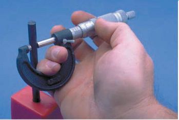
FIG. 51 Measurement using a micrometer.
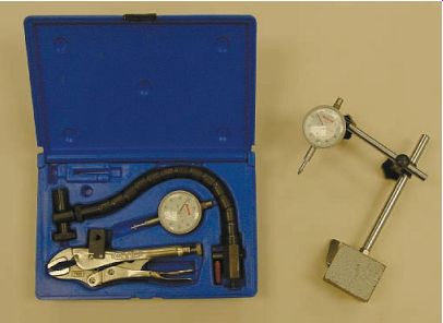
FIG. 52 Two dial indicators. The one on the right uses a magnetic base
to hold it in place, whereas the one on the left uses a flexible shaft that
locks in place.
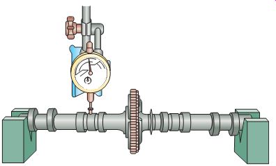
FIG. 53 A dial indicator in use measuring a camshaft from a power equipment
engine.
Dial Indicator
So far, with precision measuring tools, we've looked at tools that measure the sizes of parts. However, there are times when you'll need to measure the distance that a part moves, such as the in-and-out movement (travel) of a shaft.
The most common way to measure this type of movement is to use a dial indicator, which is simply a dial gauge with a plunger that sticks out from one side (FIG. 52) and can be used in numerous positions. Dial indicators are held in place by a magnetic base or a flexible shaft that can be locked in place once the desired location has been determined.
To use the dial indicator, attach it to a solid object (usually by means of a magnetic base or a clamping device) next to the item you're going to measure (FIG. 53). Position the dial indicator so that the plunger contacts the object whose movement is to be measured. Move the object back and forth. The dial indicates the distance that the plunger has traveled. Dial indicators are often used in engine and transmission rebuilding.
Torque Wrenches
Accurate tightening of fasteners is a key consideration in the proper operation of engines and other power equipment engine components.
In shop repair and service manuals, manufacturers specify the exact amount of torque that should be used to tighten fasteners, such as head bolts (note that most torque figures given by manufacturers are "dry torque" readings, meaning that no lubrication is used). Because it's almost impossible to accurately tighten a bolt by hand to a specified torque, special tools called torque wrenches are used. A torque wrench allows you to apply an exact amount of tightening force (torque) to a fastener. Frequently, the torque wrench is a modified socket drive handle that has a torque-measuring device built into it.
This allows you to use standard interchange able sockets when you're setting the torque on fasteners.
A torque wrench contains a measuring dial or scale. As you tighten a nut or bolt with the wrench, the dial or scale indicates how much torque you're applying. These scales are usually calibrated in SAE foot-pounds (ft-lb), inch-pounds (in-lb), or metric newton-meters (N-m). There are two common types of torque wrenches used in the power equipment engine service shop (FIG. 54).
The beam-type torque wrench contains a metal pointer rod. As you tighten a bolt, the rod points to the measured torque value (FIG. 54a).
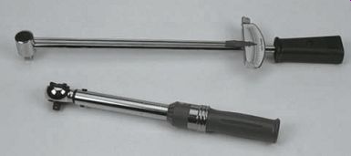
FIG. 54 The two most popular types of torque wrenches found in a power
equipment engine technician's tool collection are the (a) beam and (b) click
types.
The click-type torque wrench is somewhat easier to use than the beam type (FIG. 54b). With a click-type torque wrench, you preset on a calibrated dial the desired amount of torque before tightening the bolt. When you reach the preset torque value, the wrench clicks and no more torque is required to be applied. At low torque values, the click is inaudible and therefore you must feel the wrench flex. To preserve the calibration of the click-type torque wrench, you must release the adjustment after each use.
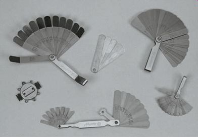
FIG. 55 A wide array of feeler gauges.
Feeler Gauges
Feeler gauges are another type of precision measuring tool. They're typically used to mea sure very small spaces between two parts, such as spark plug gaps. These small spaces are often called clearances. A typical feeler gauge is actually a set of gauges, made up of a large selection of metal blades that can spread open like a fan (FIG. 55). The blades vary in thickness to pro vide a complete range of precise measurements.
Each blade is marked with its thickness, in some cases marked in both metric and SAE sizes.
To measure the distance between two parts, insert one blade at a time between the parts until you find the blade that's an exact fit. The marked size of that blade indicates the measured clearance between the two parts. In some cases, a combination of two or more blades is used to precisely measure the clearance. In these cases, the total of the individual blade thick nesses gives the clearance.
Test Instruments
Troubleshooting and repairing power equipment engines require a wide variety of special test instruments. These test instruments are designed to test the condition of various systems.
For example, there are different instruments that you can use to test an engine's ignition and electrical systems. Let's take a brief look at some of the common test instruments.
Multi-meter
You can use different special instruments to test or measure parameters in electrical circuits within a power equipment engine's electrical system. The most common electrical testing instrument is the multi-meter (also called a volt ohmmeter or VOM). This one instrument can measure voltage, current, and resistance. The multi-meter is a box-like device that has two flexible wire test leads connected to it (FIG. 56). The ends of the wire leads hold probes that are used to contact the electrical circuitry.
When the readout on the display is digital, the meter is referred to as a digital volt-ohmmeter (DVOM).
The probes can be of either needle-point or alligator-clip design. Most comprise a combi nation to allow you to either probe or connect the test leads, depending on what component is being tested. To make measurements, the probes are made to touch different areas of an electrical circuit. The multi-meter has a display face to provide the circuit measurement information to the user. The display can be of either an analog type, which uses a moving needle (FIG. 57), or a digital display type (FIG. 56). Both types of multi-meters are popular in the power equipment engine technician's tool collection.
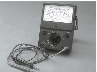
FIG. 57 A typical analog multi-meter.
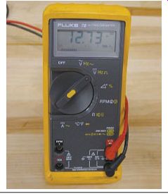
FIG. 56 A typical digital multi-meter.
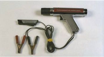
FIG. 58 Timing lights are still popular and are used to determine if the
engine's spark timing is correct.
The circuit information displayed by the multi meter helps you determine where problems, such as broken wires, faulty connections, or defective components, may exist in an electrical system.
Note that this is a brief and basic description of the multi-meter's operation. The actual operation of a multi-meter is more complex. You must al ways observe electrical safety precautions when using the multi-meter. You could damage the multi-meter and the electrical circuit if you use it improperly. More important, you could receive a severe electrical shock. We'll discuss in detail where to use a multi-meter in Section 13.
Timing Light
Although not used much today, a special device called a timing light (FIG. 58) may be used to determine if the timing of the spark impulse is correct.
You connect the timing light device between the spark plug and the plug wire, start and run the engine, and watch the timing light flash against a rotating timing mark. Every time the plug fires, the timing light will produce a flash of light (strobe) that freezes the mark. The illuminated timing mark is compared with a fixed reference mark to verify correct timing. If the timing is wrong, the two marks (fixed and rotating) will not line up. You then adjust the timing until the marks come into alignment.
Most of today's power equipment engines don't have adjustable timing; therefore, you may conclude that if the timing isn't correct, there is a problem in the system that will require a component to be replaced. Another tool that can be used with the spark plug is a spark tester, which allows you to actually see the spark of the ignition. In many cases, you would be able to adjust the spark plug gap to verify that the ignition coil is working well.
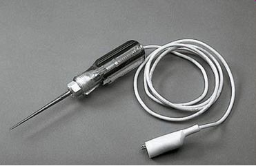
FIG. 59 A test light is a handy tool when diagnosing a problem in an electrical
system.
There are two types of test lights, self-powered and non-self-powered. Shown here is a non self-powered test light.
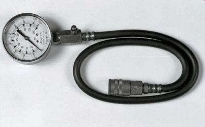
FIG. 60 Compression testers measure the amount of pressure inside an engine
cylinder and are used often on all types of power equipment engines.
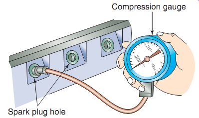
FIG. 61 Proper placement of a compression tester.
Test Lights
A test light (FIG. 59) is used to determine if electrical power is available to a particular circuit. It's often used in the diagnosis of failed lighting systems. Test lights come in two styles: self-powered, which is used to verify that a circuit is complete, and non-self-powered, which is used to verify that power is being supplied to the circuit. Both types have various uses in the service shop environment.
Before using a self-powered test light, ensure, with the help of the service manual, if it's likely to damage the circuit board being tested, because some applications of self-powered test lights can do so. In these cases, use a multi-meter.
Compression Gauge--The compression gauge is used to measure pressure in an engine cylinder (FIG. 60). You may know that a mixture of air and fuel is compressed inside of the engine's cylinder, after which the mixture is ignited. The higher the cylinder compression, the better the fuel mixture burns. As engine components wear, the compression in the cylinder decreases. By measuring the cylinder's compression pressure, you can determine if the engine is mechanic ally sound.
To use the compression gauge, unscrew the spark plug from the cylinder head and install the compression tester gauge adapter into the cylinder head in place of the spark plug (Figure 61). When you turn the engine over a number of times, the amount of pressure that's developed in the cylinder is displayed on the gauge.
Many technicians use another tool in con junction with a compression tester to deter mine the condition of a four-stroke engine-a leak-down tester. This type of tester is used to check the amount of air pressure that is allowed to escape under pressure. More information on this type of special tool will be discussed in Section 12 (on the four-stroke engines).
PURCHASING TOOLS
Few power equipment engine technicians own every type of available repair or diagnostic tool. This is because most technicians don't perform every type of repair. Exactly what tools you'll need depends on your repair specialty area and the availability of equipment at the service department where you work. In most power equipment engine service departments, technicians are required to buy their own basic hand tools and possibly some diagnostic tools.
The service department usually provides only specialized tools and expensive test equipment.
When you buy tools, remember that you'll use these tools almost every day. You must be able to depend on them. For this reason, the tools you buy should be of high quality to provide you with many years of service. It's a good idea to buy professional quality tools with a brand name. These tools are usually of the highest quality and are often backed by lifetime warranties. If a tool under warranty is damaged or fails in normal use, you can return it to the manufacturer for a replacement. You can purchase most tools individually or in sets. If you intend to enter the power equipment engine repair field, you may want to consider purchasing a complete starter set rather than dealing with individual tools. Although in most cases purchasing tools in sets works out to be less expensive than buying them individually, if you already own a reasonable assortment of quality tools, you may need to purchase only a few additional items to meet your tool needs.
As you perform more repairs and gain experience, you can add more tools to your starter set. Remember that it's better to avoid buying too many tools until you're reasonably established in your field. Before purchasing an assortment of tools that you may never use, stop and analyze your situation. When you determine the types of repairs that you'll be doing routinely, you can purchase extra tools on the basis of your specific needs. This planning will help you avoid spending a lot of money on tools that you may never need in the future. Tools aren't cheap, but they're a sound investment in your future.
Invest wisely!
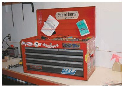
FIG. 62 A typical portable toolbox.
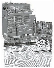
FIG. 63 Many long-term power equipment engine technicians go all out and
purchase large, floor-standing toolboxes, such as this one. Snap-on Tools Company.
STORING TOOLS
Proper tool maintenance and storage should be an important part of your daily routine. Professional technicians always take care of their equipment. Because you'll probably own a large collection of tools one day, it's important to establish good work habits and housekeeping practices early in your career. One of the most important first steps is to organize your tools so that you can find them easily. You wouldn't want to spend a lot of time looking for a tool each time you need it. And equally important, tools are an expensive investment. You should keep them locked up when you're not using them. The best way to store and organize your tools is to keep them locked in a sturdy, professional-quality toolbox. Toolboxes come in a variety of sizes and price ranges. They can be small and portable units (FIG. 62) or large, floor-standing units with wheels (FIG. 63). When choosing a toolbox for storage, always consider your future needs and plan ahead. As a professional technician, you'll continue to add tools to your collection as the need arises. So, when you choose a toolbox or cabinet, select one that will allow room for future expansion.
SERVICE INFORMATION LIBRARY
Whenever you're repairing or rebuilding a power equipment engine, the correct service reference material is a must. Because each make and model is different, you'll frequently need to look up manufacturer's information and specifications about the particular machine you're working on. An up-to-date, service information library is as essential to your work as proper tools. Franchised power equipment engine dealerships are required to keep a variety of reference books and service manuals on hand. Service manuals can be a printed copy or a CD that is used in a computer. These collections of service documentation grow every time new models and features are introduced to the market. Service manuals contain a great deal of helpful information, such as engine identification information, engine specifications, reconditioning specifications, and recommended repair procedures. Many manufacturers are making manuals and other service information available online also, as it's easier to access and update specifications online.
Most manufacturers also send out specification manuals, known as "spec" manuals. Use of the term specification here focuses on certain precision measurements made on parts of the vehicle, particularly in the engine. The exact measurements are determined by the manufacturer and are listed in the vehicle's service manual or spec manual. When you're working on a major rebuild of a power equipment engine, many of the engine specifications must be checked with precision measuring instruments we had discussed earlier in this section. These measurements are com pared with the specifications listed in the service manual. Any deviations from the listed, acceptable tolerance limits indicate a problem that should be corrected as part of the repair process. An engine must conform exactly to its specifications to operate properly. Some common engine specifications include:
Spark plug gap.
The width of the gap between the spark plug's electrodes.
Cylinder bore.
The inside diameter of the engine's cylinder.
Torque specifications.
Tightness of fasteners, usually measured in foot-pounds, inch pounds, or newton-meters.
Some technicians attempt to make repairs on a vehicle without using service manuals, but this isn't a good practice for several reasons. First, even the most experienced technicians can't remember every specification for every make and model vehicle. If you were to work on only one type of power equipment engine, you could probably handle most repairs without the use of outside references. But in almost all power equipment engine service departments, technicians are required to work on a large variety of models, often from different manufacturers. Second, manufacturers constantly make changes and improvements to their vehicles. Each year, new vehicles are introduced and more features are added to existing models. An up-to-date ser vice information library will help you stay cur rent with the latest changes to the vehicles you service. And finally, service manuals are often necessary in those cases where you weren't the person who disassembled a particular component. You may be picking up work left unfinished by someone else. With a service manual at hand, you can quickly determine how the component should be assembled and how it should be adjusted once it's installed.
Service manuals are useful tools, but they can't tell you everything. Most manuals, written with the assumption that you already know the basics of power equipment engine repair, concentrate on specifications and repair procedure sequences. Therefore, service manuals can never take the place of good training. Service manuals are simply additional tools to help you make repairs correctly and efficiently.
Summary
You should be able to easily identify common hand, power, and special tools.
It's important to know how to select the correct tool for a particular type of repair.
Use of the correct types of tools, as required by the job at hand, ensures that you're an efficient and effective technician.
There are different special tools needed to properly disassemble and reassemble power equipment engines.
There are different types of precision measuring tools and each has a specific purpose.
A proper service information library is among the most important tools that you can use.
QUIZ
Fill in the blanks in each of the following statements.
1. A is a test instrument that's commonly used to measure voltage, resistance, and other electrical parameters.
2. Power equipment engine tools can be classified into these three categories: ___, and ___.
3. A is used to tighten a nut or bolt with the exact required amount of pressure.
4. One of the most commonly used precision measuring tools in power equipment engine repair can measure inside and outside diameters as well as depth. This tool is called a ___.
5. The measuring system uses millimeters.
6. A short, six-sided rod used to tighten screws with similar indentations is the
7. Which type of wrench would be a better choice in tight places?
a. 6-point box wrench
b. 12-point box wrench
8. An air ratchet is suitable for tightening fasteners. (True/False)
9. Franchised power equipment engine dealerships have service libraries that include ___ and ___.
10. combine the open-end wrench and the box-end wrench into one tool.