AMAZON multi-meters discounts AMAZON oscilloscope discounts
(cont. from part 1)
6. ON-SITE INDIVIDUAL BUILDING SEWAGE TREATMENT
The great majority of stand-alone building sewage treatment systems in North America use a septic tank (FIG. 34) as a primary treatment device, where the settling of solids and anaerobic digestion take place. Subsequently, the effluent receives secondary treatment, which usually consists of a filtering process. Four common filtration systems are seepage pits, drain fields, mounds, and sand filters.
Occasionally, a tertiary treatment (usually disinfection with chlorine) must be used, as when outflows from secondary treatment will flow directly into surface waterways.
(a) Primary Treatment: Septic Tanks
These (FIG. 35) are commonly constructed of precast concrete, although steel, fiberglass, and polyethylene tanks are also available. The sewage enters the first chamber, where solids sink to the bottom as sludge, and scum forms on the surface.
Anaerobic decomposition proceeds, with production of methane gas. The liquid moves through the submerged opening in the middle of the tank to the second chamber, where finer solids continue to sink, and less scum forms on the surface. Finally, the effluent, about 70% purified, leaves the septic tank for secondary treatment.
The longer the sewage stays in the septic tank, the less polluted the effluent. This is why water conservation measures are so welcome with septic tank systems; the less the flow, the longer the water remains in the tank. The anaerobic decomposition process, while malodorous, is so thorough that the sludge needs only occasional removal-once in several years is about average for residences. The methane and its odor are kept within the tank, and access hatches are sometimes covered with soil (as in FIG. 35), even though this makes their occasional need to be located far more difficult.
Most systems with septic tanks will eventually experience failure, usually due to a breakdown in the secondary treatment rather than in the septic tank. With periodic removal of sludge, the septic tank itself is a reliable and simple primary treatment device. However, some types of domestic waste can disrupt the anaerobic process within the tank. The worst offenders are paints, varnishes, thinners, waste oil, photographic solutions, and pesticides.
Also to be avoided are coffee grounds, dental floss, disposable diapers, kitty litter, sanitary napkins, tampons, cigarette butts, condoms, gauze bandages, fat and grease, and paper towels.
Septic tank sizes are commonly based on code requirements that consider the number of bedrooms in residences (Table 7) or the number of waste fixture units served (see Table 2). (As shown in Table 8, maximum size may also be related to the soil condition.) Sewage flow rates are also considered. Oversized septic tanks are more expensive to install, but they release cleaner effluent and pro long the life of the secondary treatment system.
The size of the secondary treatment system is usually based upon the size of the septic tank it serves or on the expected total flow over a 24-hour period. (Flow can be estimated from Table 20.4.) Where effluent must be raised for secondary treatment, or when the total length of the secondary treatment disposal line exceeds 500 ft (154 m), a dosing tank (also called a siphon or pumping chamber; see FIG. 34c, d) is used to automatically discharge the septic tank's outflow chamber to the secondary treatment lines or sand filters.
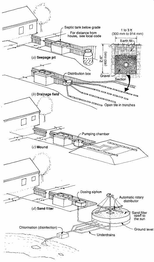
FIG. 34 For individual sewage treatment systems, septic tanks are commonly
used for primary treatment. Four options for secondary treatment are shown
here. (Tertiary treatment usually is required only for effluent discharge into
waterways.) (a) Seepage pits are rarely allowed. (b) Drain fields are the most
commonly used options. (c, d) Mounds and sand filters are more expensive to
construct and are used where high water tables preclude the use of option (b).
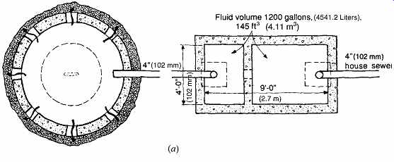
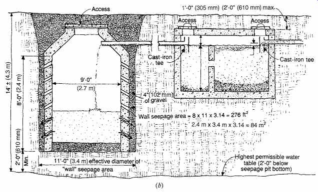
FIG. 35 Plan (a) and section (b) of a septic tank and seepage pit for a
four-bedroom house in sandy loam soil. A pit is suitable only when the earth
is absorbent and the water table low (below the pit bottom). The drawing is
not to scale.
(coming soon) TABLE 7 Septic Tank Capacity
(coming soon) TABLE 8 Septic Tank and Leaching Area Design Criteria for Five Typical Soils
(b) Primary Treatment: Aerobic Treatment Units
Active aerobic treatment units (ATUs, FIG. 36) are an increasingly popular alternative to sep tic tanks for primary sewage treatment. They are frequently used to replace a passive septic tank in a troubled system; this "upgrade" can rejuvenate an existing drain field and extend its life. ATUs depend upon air bubbled through the sewage to achieve aerobic digestion, which is faster than anaerobic digestion; hence, they can be smaller than septic tanks. They are energy-intensive and require more maintenance than anaerobic tanks. A secondary treatment process is required as well. The effluent typically is less polluted than that of septic tanks; the biochemical oxygen demand (BOD) is reduced by 90% in ATUs compared to the 50% typical of sep tic tanks.
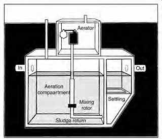
FIG. 36 Aerobic treatment unit (ATU), requiring more energy and maintenance,
but with cleaner effluent than that of a passive anaerobic septic tank. (National
Small Flows Clearinghouse.)
(coming soon) TABLE 9 Location of On-Site Sewage Disposal Systems
The sewage first enters an aeration chamber, where it is kept in turmoil so that air can continue to percolate through it. Either air is forced through the sewage by distribution lines fed by an air compressor or the sewage is stirred by a variety of devices, depending upon the manufacturer. After about a day's retention in the aeration chamber, the aerated wastewater enters a settling chamber, allowing remaining solids to settle and to be filtered out before the effluent leaves, for further treatment in a secondary process.
(c) Secondary Treatment: Seepage Pits
Also called cesspools (FIG. 35), these follow treatment by either septic tanks or ATUs. They are increasingly rare, and are appropriate only in very porous soil, where the water table is at least 2 ft (0.6 m) below the bottom of the pit. Because these pits are commonly 10 to 15 ft (3 to 4.6 m) below the earth's surface, a very low water table may be required. Another common usage of precast seep age pits is for dry wells that receive runoff from paved areas during rainstorms.
Seepage pits are sized by the square footage of the wall area exposed to the earth-the leaching area, as listed in Table 8. Placement of pits relative to buildings, water sources, waterways, and property lines is strictly controlled-see Table 9 and FIG. 37.
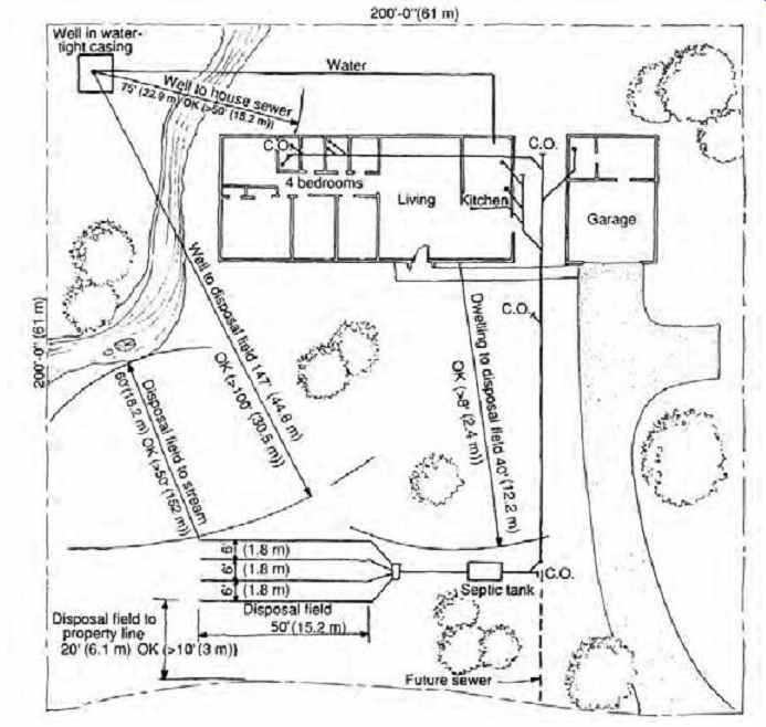
FIG. 37 Checking for required clearances on a suburban lot. Although the
40,000-ft 2 (3716-m2) lot is more than the minimum required, space should be
left for a backup disposal field (of equal size) in case of failure of the
original field.
(d) Disposal Fields
These are very commonly used as a secondary treatment method (FIG. 38) because they are relatively inexpensive to build and do not require a water table so deep-or soil so permeable-as do seepage pits. Drain lines consisting of either perforated pipes (of many approved materials) or square edge agricultural tile, 4 in. (102 mm) or more in diameter (with the ends of the tiles separated by ¼-in. [6-mm] openings), are used. These lines are placed in shallow trenches, on a bed of gravel, and covered with gravel. The effluent runs out of these lines and stands in the interstices of the gravel until it seeps into the earth. In effect, the gravel provides spaces that act as a dry well to receive the fluids and accommodate them until they slowly sink into the ground.
Disposal fields are located according to regulations such as those given in Table 9 and sized in relation to total sewage flow and septic tank size (see Tables 8 and 10). Although Table 8 shows the maximum absorption capacities for soils based on gal/ft 2 (L/m2) over a 24-hour period, a common alternative is to use percolation tests. For such tests, a trial pit is dug and water poured into it. The absorption in gal/ ft 2 (L/m2) over a 24-hour period is determined from this test. Some codes require design sizes based upon percolation test data. Codes often require that an area equal to the required drain age field size be set aside for use in the event of failure in the original field.
Design guidelines for sizing disposal fields were presented in Section 20.3, but a more accurate method is shown here. The trench width, depth, and spacing shown in FIG. 38 are typical, but other combinations can be used, provided that they meet the requirements listed in Table 10.
(coming soon) TABLE 10 Disposal Field Trenches
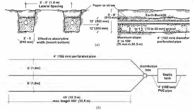
FIG. 38 Example 3. Tile drain field for a four-bedroom house. Although
the drawings are not to scale, the dimensions show a required area of about
20 × 50 ft (6 × 15 m) on the lot. Because paving is not permitted over drain
fields, sewage treatment on a small lot demands considerable creativity. (a)
Transverse and longitudinal sections. (b) Schematic plan. (Redrawn with SI
units by Nathan Majeski.)
(e) Mounds with Leaching Beds
These (FIG. 39) represent a newer solution in the United States and thus may require special approval. The guidelines for leaching-bed sizing are essentially similar to those for drainage tile disposal fields. The absorption area for leaching beds, how ever, must be 50% greater than that required for trenches. The bottom of the leaching bed generally must be at least 5 ft (1.5 m) above the water table, although in water-scarce areas, officials may reduce this requirement.
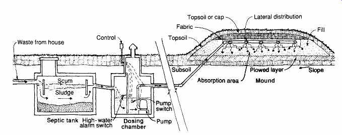
FIG. 39 Mounds with leaching beds offer a disposal option when the water
table is high. The system serves a two- or three bedroom home. (Adapted from
Converse, 1978.)
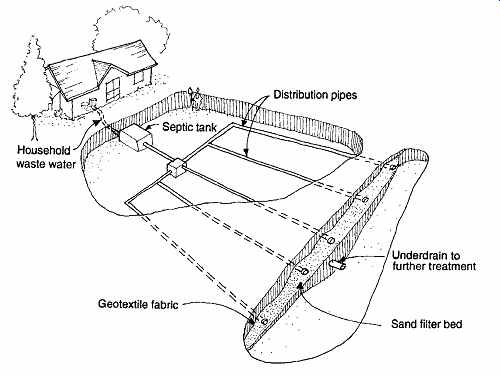
FIG. 40 Buried sand filters appear to be like the common disposal fields,
but are deeper and may require an impermeable membrane liner. (National Small
Flows Clearinghouse.)
(f) Buried Sand Filters
Slow sand filters for treating supply water were discussed in Section 2.
Buried sand filters (FIG. 40) work in a similar way, using primarily biological but also physical and chemical processes to clean wastewater. The medium is most commonly sand, although other locally available materials such as crushed glass, mineral tailings, bottom ash, and so on have been used. The grain size ranges from 0.01 to 0.1 in. (0.3 to 3 mm) in diameter.
The layout is similar to that of the disposal fields described in Section 6(e), but these filters, themselves 24 to 36 in. (610 to 914 mm) deep, usually require an excavation of 4 to 5 ft (1.2 to 1.5 m). The filter bed must be level and sited to avoid con tact with groundwater and excess surface water runoff. Some authorities require the sand filter to be contained in an impermeable membrane liner.
Underdrain pipes and a graded layer of washed gravel or crushed rock are placed on the bottom of the filter bed, with the finer gravel on top to keep the medium from washing into the underdrains.
Then a layer of fine gravel first, with coarser gravel above, is placed around and over the distribution pipes. A geo-textile fabric covers the top of the entire filter bed, which in turn is covered by backfill material. A properly constructed buried sand filter that receives properly digested waste from a well-maintained septic tank should last for up to 20 years without maintenance.
Buried sand filters are one remedy for failed disposal fields. They are also used where high groundwater, shallow bedrock, or poor soil preclude use of the simpler disposal field. Although buried sand filters may require considerable site area, the ground surface can be used for lawns or other non-paved surface activities. More detailed information on the sand filter types discussed here is available from the National Small Flows Clearinghouse.
In general, sand filters are designed for normal dosing twice a day; they need time to allow the filter medium to drain between doses. The water that filters through the medium is collected in underdrains that are sloped toward an outlet and vented to the surface at the upstream end.
This vent is a potential source of odors. The water is then taken either to a disinfection (usually chlorination) unit or to a disposal field for subsurface discharge.
Water from sand filters has been cleansed of many pathogens, such as harmful bacteria and viruses, and is therefore more likely to be approved for a down-line disposal field. Typical values for three types of sand filters are shown in Table 11.
(Open and recirculating sand filters are discussed in the next section.)
(coming soon) TABLE 11 Sand Filter Design Values
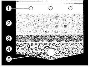
FIG. 41 Open sand filter receives wastewater from above through (1) distribution
pipes (or a thin layer of flooded waste water). A filter medium (2) such as
sand is on top, then (3) fine gravel, then (4) coarse gravel, surrounding the
(5) under drain. Slow sand filters are very similar. (National Small Flows
Clearinghouse.)
7. ON-SITE MULTIPLE-BUILDING SEWAGE TREATMENT
The first approach to multiple-building treatment involves providing septic tanks at each building for primary treatment. Then the outflows from the individual septic tanks are combined and enter a secondary treatment process. Either of two specific types of sand filters can be employed for this purpose.
There are several advantages to this approach. The effluent lines from the septic tanks carry no solids; they can be much smaller in diameter and placed in shallower trenches than conventional sewer lines.
The runs are far shorter, because distant centralized treatment plants are not involved. With sand filter secondary treatment, the septic tank waste water is more likely to find a recycling use, such as irrigation.
(a) Open Sand Filters
Also called intermittent sand filters, these are very similar in construction to slow sand filters. They are nearly identical in performance to buried sand filters (FIG. 40); the difference is that these are at least partially aboveground. A detail of the filter medium is shown in FIG. 41.
Table 11 shows that they are able to accept a somewhat higher flow than a buried filter, so they require less area than a buried filter, but the surface is no longer usable for any other purpose. (A removable cover is typically used for odor control, despite the "open" name.) They are used on systems with flows of up to 120,000 gpd (454,240 L/day) of wastewater. Frequently, two such open filters are built so that one can rest while the other is in use. Alternatively, two filters may be used in series, with an even cleaner resulting final effluent.
(b) Recirculating Sand Filters
These eliminate odors by ensuring an adequate supply of oxygen to the wastewater. The recirculating sand filter (FIG. 42) first receives water (from the septic tank or other primary treatment) into a recirculation tank. This tank has a pump, a timing mechanism, and float valves. Either in timed doses or when triggered by the float valve, doses of water are pumped to the sand filter. The treated wastewater collects in the underdrain, where the majority (75% to 80%) is directed back to the recirculation tank. Thus, mixing with the septic tank effluent and being pumped to the sand filter, the result is weaker (cleaner) effluent, containing more oxygen, entering the sand filter. This eliminates odor and allows a slightly larger filter grain size, making the system less prone to clogging. Table 11 compares sand filter types, showing the highest allowable flow rates per surface area for the recirculating sand filter.
At Stonehurst, a 47-lot subdivision in Contra Costa County, California, 1500-gal (5680-L) sep tic tanks serve each unit; each tank has a screened effluent vault, keeping solids out of the effluent lines. The effluent is taken through small-diameter, variable-grade sewers (located under the roadway) to a recirculating granular medium filter. (Homes lower than the roadway use effluent pumps at the septic tank outflows.) Outflow from the recirculating filter is then taken to a UV recirculation tank, where it is treated by UV radiation (see Fig. 21.6). From this tertiary treatment area, it is conducted to a subsurface drip irrigation system serving a com munity park. In winter, a 2.5-acre (1-hectare) com munity soil absorption field is utilized.
(c) Lagoons
These basins need sun, wind, and more land area than other methods, but are very simple to maintain and very low in energy use. They usually must be lined to prevent wastewater from polluting the groundwater. Sometimes the outflow must undergo further treatment before release. If lagoons are not square or round, their length should not exceed three times their width. Outflow and inflow should be at opposite ends. Detailed information is available from the National Small Flows Clearing house (1997).
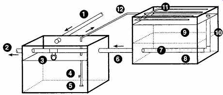
FIG. 42 Recirculating sand filters periodically distribute a cleaner, more
oxygen-rich effluent to the sand filter. This eliminates odor and allows a
larger medium grain size. (1) Effluent from pretreatment (such as a septic
tank). (2) To disinfection/discharge. (3) Float valve. (4) Bleed line. (5)
Submersible pump. (6) Recirculated effluent line. (7) Perforated underdrain
piping. (8) Layered support gravel. (9) Filter media. (10) Riser pipe. (11)
Distribution piping. (12) Recirculation pump discharge to recirculating filter.
(National Small Flows Clearinghouse.)
Anaerobic lagoons are usually used as the first of at least two lagoons in series. Working much like a septic tank, they hold wastewater for 20 to 50 days and are relatively deep, 8 to 15 ft (2.4 to 4.6 m). With a surface of floating scum that blocks oxygen from the wastewater, they are unsightly and malodorous.
Aerobic lagoons are shallower than other lagoons, so sunlight and oxygen from wind and air can better penetrate. Aerobic bacteria and algae do the work of cleaning the wastewater. These are best in warm climates where freezing is not a threat.
They hold water for 3 to 50 days. The bottoms are either paved or lined to prevent weeds from growing within the lagoon.
Aerated lagoons take the aerobic lagoon a step further, actively stirring and adding oxygen to the lagoon. Because they speed aerobic action, they require shorter retention time and less land area than a passive aerobic lagoon.
Facultative lagoons (also called stabilization, oxidation, photosynthetic, or aerobic-anaerobic ponds) are the type most commonly used by small communities and individual households. They work in most climates and require no machinery. They require about 1 acre (0.4 hectare) for every 50 homes (or for every 200 people) served, are 3 to 8 ft (0.9 to 2.4 m) deep, and are designed to hold wastewater for 20 to 150 days (the longer period in cold weather).
Three layers form in these lagoons; the top is an aerobic zone, the middle is the facultative zone, and at the bottom is the anaerobic zone. The depth of the surface aerobic zone depends upon how much sunlight, wind, and rain can contribute oxygen; the deeper this zone is, the better it controls odors rising from the anaerobic zone. Therefore, these lagoons should be sited with full access to both sun and wind.
Down in the anaerobic zone, anaerobic bacteria convert sludge to gases, including hydrogen sulfide, ammonia, and methane. As these gases rise, they provide food for both the aerobic bacteria and the algae in the aerobic zone. Sludge accumulates more quickly in cold climates; sludge removal should be expected every 5 to 10 years.
(d) Advanced Integrated Wastewater Pond System (AIWPS)
At California Polytechnic State University, San Luis Obispo, there is an innovative proposal to create an integrated infrastructure facility combining campus wastewater treatment and solid waste processing. In addition to the waste treatment and resources recovery for this campus of 18,000, the schematic design for the Energy Efficient Resource Recovery (E2R2) Facility includes an educational facility, a wildlife habitat, and park facilities.
The wastewater and related wetlands proposals are shown in FIG. 43; the solid waste facility appears in Fig. 23.1 (next section).
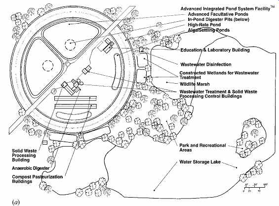
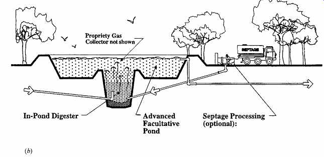
FIG. 43 Schematic design proposal for wastewater treatment at the Energy
Efficient Resource Recovery (E2R2) Facility at Cal Poly, San Luis Obispo. (a)
Site plan. (b) Effluent enters the advanced facultative pond (AFP) through
the in-pond digester, where solids settle, undergo methane fermentation, and
are reduced to ash. Rising biogas is channeled by a proprietary submerged gas
collector and passes through a highly aerobic surface layer where impurities
are removed, yielding methane-rich biogas at the surface. (c) AFP effluent
then goes to the high-rate pond, where it is slowly moved along the shallow
channels by an energy-efficient paddle wheel providing optimum solar exposure
and enabling the profusely growing algae to supply abundant oxygen for oxidation
of wastewater organics and disinfection of pathogens. Subsequently, effluent
moves into the quiescent Algal Settling Pond where algae settles and is periodically
removed for beneficial use. (d) Effluent then moves into constructed wetlands,
where the plants in this system create an ideal environment for invertebrates
and vertebrates (in free surface wetlands) and aerobic and anaerobic microbial
populations to thrive and provide further treatment and effluent polishing.
Finally, the effluent from the wetlands is disinfected by ozone or UV disinfection
systems and stored in a lake that is part of a campus park and recreational
facility. (Courtesy of Dr. William Oswald, Professor Emeritus of Civil and
Environmental Engineering and Public Health at the University of California,
Berkeley, and Principal of Oswald Engineering Associates, Inc.; Dr. Bailey
Green, Research Engineer at the University of California, Berkeley, and Principal
of Oswald Engineering Associates, Inc.; and Professor Daniel Panetta, Architecture
Department, Cal Poly, San Luis Obispo.)
Three ponds are used in the AIWPS facility (Oswald, 1990; Oswald et al., 1963). The first is the advanced facultative pond (AFP) (FIG. 43a), which includes an in-pond digester (IPD) or anaerobic fermentation pit at the bottom, and an oxygen rich aerobic surface water layer. Two AFPs used in parallel allow fail-safe operation. This design enables isolation and treatment of toxic substances in the event that such material is accidentally released into the community sewer system. Conventional sew age treatment plants typically cannot isolate or treat accidental toxic releases in wastewater due to their short processing time.
The raw sewage enters the system near the bottom of the IPD, where anaerobic bacteria slowly reduce biosolids to ash (Oswald et al., 1994; Green et al., 1995b). Biochemical oxygen demand (BOD) is reduced to 60% to 80%, and minimal accumulation of refractory solids (sludge) has been demonstrated since the late 1960s.
Using earthwork construction for the ponds allows them to be quite large and deep, without the substantially higher costs of concrete and steel construction typical of conventional wastewater treatment facilities. A berm surrounding the IPD prevents mixing of aerobic water with the influent below, whether by wind or thermal inversion.
The aerobic upper layer oxidizes any malodorous biogases rising from the IPD. The biogas generated in the IPD is scrubbed as it passes through the water column and the aerobic surface layer. At the current campus population, between 3000 and 5000 ft 3 (85 and 142 m3) per day of methane (CH4) are estimated to be available for collection from the IPD and use as fuel (Green et al., 1995a).
The second pond is the high-rate pond (HRP) designed to grow algae (FIG. 43b). The lined channels in this pond are approximately 3 ft (1 m) or less in water depth and include a paddle wheel (see FIG. 49) to slowly mix the primary effluent.
The HRP design allows maximum oxygen production by algal photosynthesis due to optimum exposure to sunlight and abundant nutrients. The pond's aerobic and facultative bacteria oxidize most of the soluble and readily biodegradable BOD.
The next pond in the series is an algal settling pond (ASP) (FIG. 43c). The quiet waters of this pond allow 50% to 80% of the algae to settle over several days' residence time. The settled algae are periodically harvested, and the algal biomass does not produce objectionable odors. When properly disinfected, the harvested algae, rich in nitrogen and phosphorus, can be used as fish or livestock feed or as a nitrogen source in compost.
Near St. Helena, California, an AIWPS facility has functioned since the late 1960s. During this time period, no sludge removal has been necessary, attesting to the efficiency of the methane fermentation process. The facility is near several large win eries and is considered a good neighbor without odor problems.
While a maturation pond usually follows the ASP in an AIWPS facility, various appropriate treatment components can subsequently be used to achieve advanced tertiary treatment-the highest wastewater reclamation and reuse standard required by the state of California (Green et al., 1996). In the proposed schematic design, the ASP effluent flows into a constructed wetland.
(e) Constructed Wetlands
Wetland surrogates constructed specifically for waste treatment are shown in FIG. 43c. In the schematic design, two parallel constructed wet lands are proposed, allowing a comparison between their outflows.
The free surface wetlands (FSW) consist of shallow open basins or channels that are lined to pre vent seepage. Soil supports a succession of wetlands vegetation, nourished by a continuing flow of effluent from the initial wastewater treatment system(s) (such as a secondary AIWPS facility, septic tank, etc.). Although the water surface is exposed to beneficial air and sunlight, proper design is required to mitigate human contact with the treated effluent in FSWs. It is also necessary to address potential problems such as mosquitoes or other water-borne insects.
The subsurface flow wetlands utilize a lined treatment basin filled with a coarse medium such as large gravel or crushed rock. The large voids (if properly designed) allow the effluent to flow freely through rocks and plant root systems. The relation ships among gravel size, slope of bed, and rate of flow is complex and is described in detail in an EPA document (1993). A layer of soil is used to cover the gravel bed, so subsequent human contacts with the effluent and insect problems are precluded.
In either type of constructed wetland system, saturated and nutrient-rich conditions encourage the growth of both aerobic and anaerobic microbes and certain invertebrates. The most common plants include varieties of scripus (bulrushes), phragmites (reeds), typha (cattails), canna, and iris. These plants not only provide large amounts of surface area for microbial activities, but also create an aerobic zone underwater by transporting air through their stems to their roots. A thin aerobic environment results among the root hairs.
Constructed wetlands become a vivid, colorful demonstration of how, in nature, there is no such thing as waste. After passage through a slow sand filter and final disinfection, the reclaimed water from the E2R2 facility can provide campus landscape irrigation water, be released into the campus creek to assist with habitat restoration, or be used for aquifer recharge. Arcata, California, completed its wetlands treatment system in 1986. This system draws several hundred species of birds, as its abundant vegetation removes nutrients from, and allows habitat reuse of, the city's treated wastewater.
(f) Greenhouse Ecosystems
When constructed wetlands are moved indoors, greater control and less required area become possible. As pioneered by marine biologist John Todd at Ocean Arks International, Living Machines are a series of tanks, each with a particular ecosystem, that form a "stream." The stream is followed by an indoor marsh; together they achieve a high degree of tertiary wastewater treatment.
These enclosed systems typically cost less to construct and about the same to maintain as conventional sewage treatment plants, but use less energy because photosynthesis (solar energy) and gravity flow largely replace energy-intensive pumps and large-scale aerators. These systems do not harm the environment with a final dose of chlorine, and they produce about one-quarter of the sludge of conventional systems. Because they are pleasant to look at and smell much like commercial greenhouses, they can be located within the neighborhoods they serve. This can save the huge costs associated with large-diameter, deep-trench sewer lines and pumping stations necessary with distant, centralized treatment plants.
A diagram of one greenhouse ecosystem is shown in FIG. 44. This Living Machine begins with an anaerobic bioreactor, in effect a septic tank where solids are reduced to sludge and methane gas is produced. From here the wastewater passes to aerated tanks and then to ecological fluidized beds, each with a particular combination of bacteria, algae, snails, and fish. The further along the treatment process, the more advanced the ecosystem, with goldfish (carp) growing in the final clarifier. This process depends upon the following food chain: (1) aerobic bacteria consume suspended organic matter and convert ammonia into nitrites and then nitrates; (2) algae and duckweed feed on the products of the bacterial action; (3) snails and zooplankton eat the algae, while floating duckweed provides shade that discourages algal growth in the later stages of the process; (4) fish eat the zooplankton and the snails. Plants range from water hyacinth in the early stages to an increasing variety of specialized "accumulators" that remove troublesome phosphorus, heavy metals, and so on. Papyrus, canna lilies, bald cypress, willows, and eucalyptus (among other plants) all have a role. When trees outgrow the greenhouse, they are transplanted outdoors-but they are long-term storage for the heavy metals they absorb, not final solutions, because heavy metals will be returned to the earth when the trees die and decompose.
Plants can be sold to nurseries or ground up as compost; the fish also enrich the compost. The smaller fish (shiners) can be sold as bait fish.
These are small enough to dart back and forth in the piping between tanks, choosing their water quality. If a toxic slug of waste enters the system, they swim to later, clearer tanks until the danger is past.
FIG. 44 A Living Machine enclosed within a greenhouse uses a food chain in a series of ecosystems to treat wastewater. (Living Technologies, Inc.)
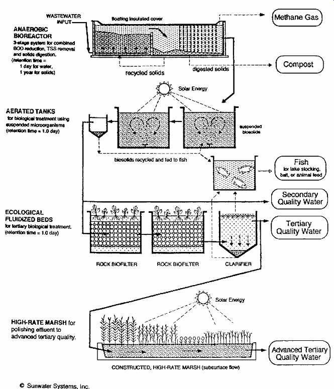
FIG. 45 (a) A greenhouse in a mobile home park in British Columbia encloses
the 12 solar tanks and marsh of a Solar Aquatics Sys tem, designed by Ecological
Engineering Associates and ECO-TEK, Inc. (Photo by Charles Rusch.) (b) In the
middle of an urban block in Denmark, a Living Machine is a good neighbor. (Photo
© 1996 by Robert Peña.)
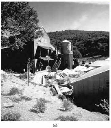
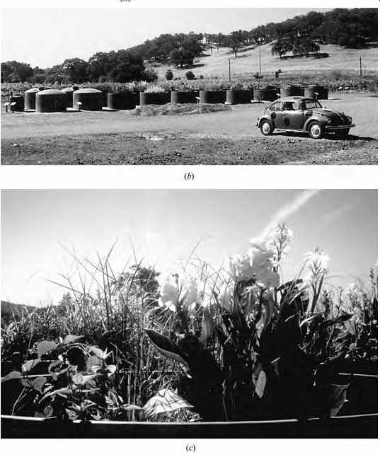
FIG. 46 In the mild climate of California's Sonoma Valley, the waste from
the Sonoma Mountain Brewery (a) is treated by an outdoor Living Machine (b).
Flow is from left tanks to right tanks, then to a marsh. (c) Calla lilies and
other plants lend beauty as well as function to this open aerobic tank. (Designed
by Living Technologies, Burlington, VT.)
The greenhouse solar aquatic system in FIG. 45a cleans the wastewater from a mobile home park on Vancouver Island, British Columbia.
In FIG. 45b, a striking Living Machine design occupies the center of an urban block in Kolding, Denmark.
In milder climates and with specialized wastewater, these processes can be achieved without the greenhouse enclosure. The Sonoma Mountain Brewery's Living Machine (FIG. 46) near Sonoma, California, occupies about 1 acre (0.4 hectare) and treats a maximum flow of 7800 gpd (29,525 L/day) of waste from the brewery process. Two streams move in parallel, allowing a comparison of their outflows as experiments with detailed ecosystems are conducted. A part time operator manages this treatment plant.
After an underground anaerobic holding tank, flow moves to:
1. Closed aerobic reactors, each holding 2500 gal (9463 L). Air is blown through the tanks from the bottom (an adjacent small building encloses the blower); wastewater spends about 15 hours in these tanks. Next are-
2. Open aerobic tanks, four per stream. Plants, snails, and organisms can migrate among the agitated tanks, choosing their preferred level of nutrients ("pollution"). Water leaving the last of these tanks is much cleaner; water and sludge collected from the tanks are taken next to the-
3. Clarifier. Shaded by water hyacinth, algae can not grow in the water at this advanced stage. In this quiet-water environment, solids settle out and are then pumped to an adjacent-
4. a. Open-air reed bed ("composter"), where they are dried and then composted. The com post will serve as nutrient for the hops used in the brewing process. Excess water percolates through an underlying sand bed and is returned to the beginning of the Living Machine streams. Meanwhile the clarified water passes next to-
b. Ecological fluidized beds (two per stream), whose purpose is to further polish the wastewater. Water circulates many times through this section, pumped from the plant-shaded perimeter into a rock bed at the center. In this bed, microorganisms continue to clean the water.
From the second ecological fluidized bed, water moves to an underground-
5. Irrigation pond, from where it is filtered through a-
6. Constructed wetland for further purification.
Finally, it is welcomed for irrigation of the hops and grapevines grown on site.
The IslandWood environmental education cam pus on Bainbridge Island, Washington, prominently features a Living Machine (FIG. 47) as a focal point near a major classroom. This location brings waste processing into the consciousness of those using the campus and reminds us that human wastes do not literally just disappear if piped off site. In this cool climate setting, the greenhouse provides a thermal environment to support the biological waste treatment processes that are the heart of a Living Machine.
(g) Pasveer Oxidation Stream
This method of sewage treatment (Figs. 48 and 49) has been adopted at the New York Institute of Technology. Serving the 450-acre (182-hectare) campus at Old Westbury, Long Island, New York, this system provides on-campus sewage treatment, which returns purified effluent to the ground through 48 leaching wells located under the athletic field. The groundwater, thus restored, provides a contributing source of water for 400-ft- (122-m)-deep wells, distantly located, that furnish part of the water supply for the campus buildings (see FIG. 48).
A few of the original small buildings, later converted to administration offices and classrooms, are still served by septic tanks and leaching fields. There was no public sewer near the campus, and in the 1970s the health authorities ruled out the use of septic tanks for the numerous additional buildings that were contemplated.
The oxidation stream process applied here was developed by the Netherlands Research Institute for Public Health Engineering and is now in operation in many U.S. locations as well as in Europe. It is considered to be a modified form of the activated sludge process (see later discussion of the Oceanside Plant in Section 8b), with aerobic digestion and periodic sludge removal.
The mechanical aerator (FIG. 49), which keeps the stream of sewage moving and provides the oxidation necessary for aerobic digestion, is an important feature. In this design, sludge-drying beds are placed on an island, surrounded by the continuously moving oxidation stream.
Another feature of the system is its low profile (FIG. 50), readily screened by trees. The aerobic digestion process is not malodorous. Sound is produced by the splashing water-wheel action of the mechanical aerators; no air compressor is required (reducing noise generation).
The plant has a full-time accredited operator; there are also two assistants and one relief opera tor. This design provides for an eventual population of 4330, with a 340,000-gpd (1,287,010-L/day) flow. Sludge was removed from the drying beds twice in the first five years of operation.
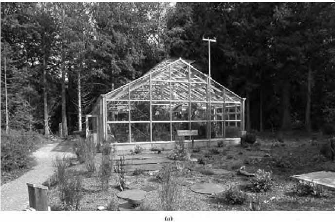
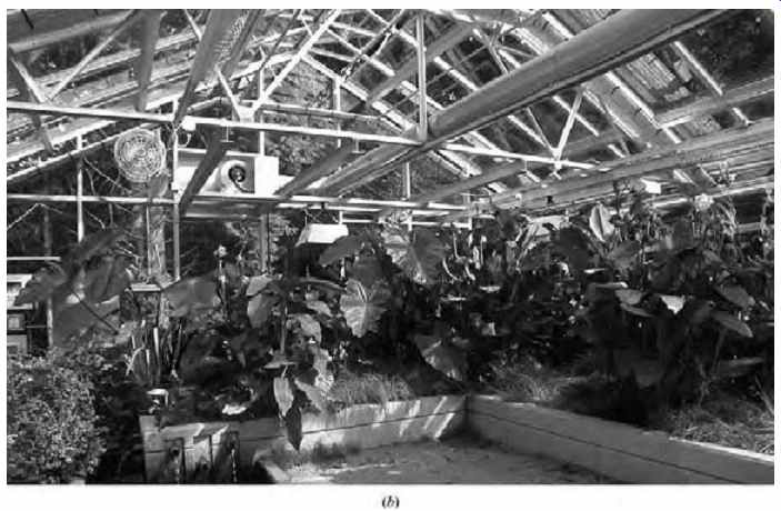
FIG. 47. (a) Greenhouse enclosing a Living Machine on the IslandWood campus
on Bainbridge Island, Washington. (b) Interior view of the IslandWood Living
Machine, showing plant materials that are an integral aspect of this biological
waste treatment approach.
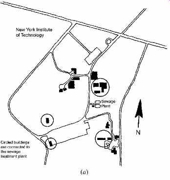
FIG. 48 Sewage treatment plant, New York Institute of Technology (NYIT).
(a) The treatment plant's location is central to all of the buildings it serves,
an efficient choice.
(b) Layout of the treatment plant. Because of the plant's odor less operation,
its proximity to campus buildings poses no problem. (Courtesy of Bogen Jenal,
Engineers, P.C. Redrawn by Amanda Clegg.)
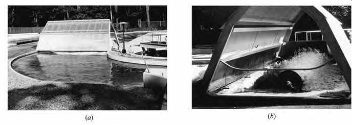
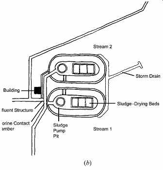
FIG. 49 Details of NYIT treatment plant. (a) Rotor with a plastic "greenhouse" cover.
(b) The rotor induces oxidation in this oval circulating stream. (A similar
mechanism serves the high-rate pond in FIG. 43.)
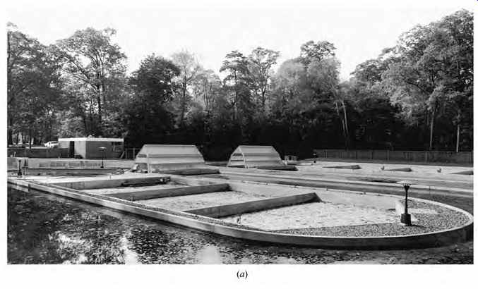
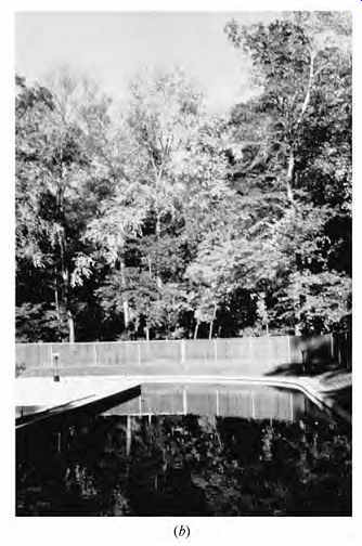
FIG. 50 NYIT sewage treatment plant at completion. (a) The only projections
above ground level are the office/laboratory and the plastic covers over the
rotors. (b) The oxidation stream does not appear turbulent here, but it becomes
so under the action of the mechanical aerator (rotor).
8. LARGER-SCALE SEWAGE TREATMENT SYSTEMS
Two examples of community-wide sewage treatment are presented here-one for a small, water-scarce community near San Diego, California, and one for an oceanside urban neighborhood in San Francisco.
(a) Padre Dam Municipal Water District
The Santee Water Reclamation Plant (FIG. 51) incorporates innovations in water conservation and recycling developed during the 1960s and 1970s.
The Padre Dam Municipal Water District is a region where rainfall is less than 15 in. (380 mm) per year.
It has no local water supplies, so water is imported 300 miles (480 km) from the Colorado River. If conventionally treated, the wastewater resulting from water usage would be discharged into the Pacific Ocean. Alternative sewage treatment (shown here) processes this fluid waste for secondary uses such as irrigation and recharging of groundwater. Many municipal potable water supplies are taken from rivers often heavily polluted with sewage. After treatment, water from such sources is pumped into domestic water supply mains. Therefore, district officials here decided to install a system that would make use of purified wastewater for many secondary uses.
However, would such a concept be acceptable to the public? An effective public relations program concurrent with the incorporated technological advances has proved successful.
The project involved building a sewage treatment plant and utilizing seven pits left over from prior surface mining of sand and gravel. After partial purification of the sewage at the plant through the first two stages of a conventional activated sludge process, the effluent is discharged to form the lakes adjacent to the plant. This provides tertiary (oxidation) treatment, after which the cleaner effluent is pumped to a filter area at the north end of the complex, where it is further purified by flow through sand and gravel. Chlorination is performed, and the water then flows through a series of seven lakes, Nos. 7-6-5-4-3-2-1, in that order.
The appearance of new lakes in this semiarid region created initial interest that was rapidly augmented by a very clever program. At first, the lakes were fenced in. Then the fences were removed. Next, the seven lakes were made avail able for boating. They were stocked with fish, and careful studies were made that indicated that the fish were healthy and flourishing. Fishing was per mitted, but for a while, all fish had to be returned to the water. Anglers were later permitted to keep and consume the fish. Finally, swimming was permitted. The overflow from the last lake, No. 1, discharges into Sycamore Canyon Creek and is used for irrigation of a golf course and the recharging of groundwater.
(b) Oceanside Water Pollution Control Plant
Imagine the challenge of locating a major new sewage treatment plant on the shore of the Pacific Ocean, within the city of San Francisco, immediately adjacent to both the city zoo and a well-established neighborhood. This plant treats all the sewage in the western San Francisco watershed, an average dry weather flow of 21 million gal/day (79,491,720 L/ day). The treated effluent is discharged through an ocean-bottom pipeline, 4.5 miles (7.2 km) offshore, with effluent and ocean water quality monitored by an on-site laboratory. Sludge is shipped north to serve as the required daily cover for a landfill near Novato. The plant itself is concealed by large earth berms, through which entry and exit tunnels carry plant traffic. And the odor? It is completely contained within a huge underground complex of wastewater basins and channels, over which the zoo has proposed to build its new Mammal Conservation Center on 5 ft (1.5 m) of topsoil cover.
Exhaust air from the underground plant is filtered through activated carbon and potassium permanganate before release.
The process is shown in simplified form in FIG. 52a. Incoming sewage passes through a bar screen and grit chambers, which remove the largest objects as well as grit, sand, and gravel (these are trucked to a landfill). Then the water flows to the primary clarifier, in which floating scum is skimmed off, and sludge settling on the bottom is pumped to the egg-shaped anaerobic digesters (FIG. 52b). The wastewater flows next to aeration tanks where bacteria grow fat, feeding on and breaking down the remaining dissolved and suspended solids. Next is the secondary clarifier, where the fattened bacteria (activated sludge) sink to the bottom. Part of this activated sludge is returned to the aeration tanks to bolster the bacterial culture there. The remainder is thickened and pumped to the digesters.
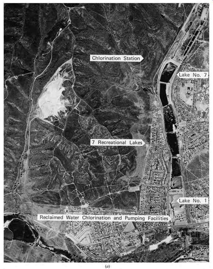
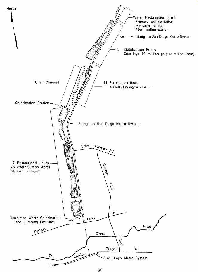
FIG. 51 Santee Water Reclamation Plant and Santee Park and Recreational
Facilities, Padre Dam Municipal Water District, California. (a) Aerial photograph
of the Santee Plant, including the seven recreational lakes. Note the location
of the San Diego River at the bottom of the photograph. The water reclamation
plant and the stabilization ponds do not appear in this aerial view. (b) Raw
sewage from the community of Santee enters the treatment plant, which is located
at the top of this diagram. The process then proceeds south to the point where
reclaimed water is pumped to irrigation or recharges groundwater. Sludge is
pumped to the San Diego Metro system. The plant is not burdened by storm water,
which is recharged to the ground locally in the community.
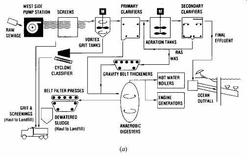
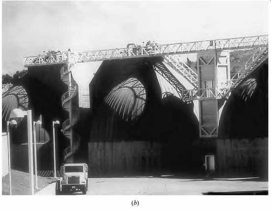
FIG. 52 The Oceanside Water Pollution Control Plant, San Francisco, is
largely underground, as well as hidden behind high earth berms. (a) Flow diagram.
(Courtesy CH2M Hill and the City/County of San Francisco.) (b) View of some
of the egg-shaped anaerobic digesters from within the berm walls. Biogas produced
within the four 750,000-gal (28,375-m3) digesters supplies about 20% of the
electricity used in the treatment plant.
Thus, the anaerobic digesters receive both primary sludge and thickened, activated sludge.
As this sludge is stabilized and reduced in volume, biogas is produced: enough to heat water for both process and facility heating and to generate about one-fifth of the electricity used within the plant.
Sludge leaving the digesters is dewatered in belt presses, then hauled to the landfill. During summer, biosolids are spread on agricultural land for soil enrichment.
Questions remain about such use of biosolids.
Although a 1998 EPA national survey of sewage sludge found toxic chemicals at such low levels that regulation was deemed unnecessary, concentrations of certain industries may produce local chemical or radioactive sludge pollutants at higher levels.
Intercepting such wastes at their source, rather than allowing them into the sewage stream, seems an obvious imperative.
9. RECYCLING AND GRAYWATER
These sections on water and waste have illustrated four common "grades" of water in buildings:
Potable water (usually treated, suitable for drinking) Rainwater Graywater (wastewater not from toilets or urinals) Blackwater (water containing toilet or urinal waste) Two more categories are:
Dark graywater (from washing machines with dirty diaper loads, kitchen sinks, and dishwashers; usually prohibited for reuse) Clearwater (backwash water from reverse osmosis water treatment; condensation from a cooling coil) After considering the many blackwater sew age treatment complications described in the previous section, it might be expected that graywater reuse would, by contrast, be a simple matter. How ever, there are lingering prejudices against waste water of any kind that complicate water recycling, if not prohibit it outright. This section presents some future approaches that may be more actively implemented if water conservation is to be taken seriously, followed by some code-mandated approaches.
Rainwater, given an adequate supply, could meet the need for many uses of water in and around a building: bathing and laundry, toilet flushing, irrigation, and evaporative cooling, for example. Little or no treatment of rainwater is needed for such uses.
Blackwater requires much more extensive treatment, given its high concentration of human waste. However, this may be the easiest waste stream to eliminate, given the several waterless alternatives discussed in Section 1.
Graywater (also spelled greywater) reuse opportunities are more limited than those of rainwater, because graywater carries increased threats from pathogens. It must undergo treatment before reuse in toilet flushing. It is likely to contain soap, hair, and, occasionally, human waste (from soiled clothes in the laundry). If it is to be used in drip irrigation systems, filtering is essential. If kitchen wastes are included, grease and food solids add to the problems. Graywater may well be dirtier than rainwater, but its supply is likely far more predict able and constant. However, codes tend to limit the use of graywater to underground landscape irrigation for single-family houses.
The collection of these separate types of water poses a problem. In the early years of indoor plumbing, rainwater, graywater, and blackwater were mixed together, which severely overloaded sewage treatment facilities in rainy weather.
Today, graywater and blackwater are typically mixed, with rainwater being kept separate. There are precedents for keeping all three separate, how ever (FIG. 53).
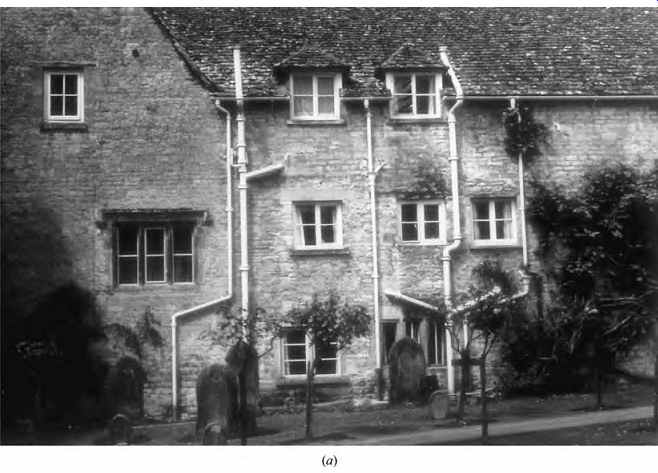
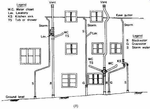
FIG. 53 Residence of the 27th Vicar of the Parish Church at Bibury (established
A.D. 1086) in the English Cotswolds. (a) Clearly, the plumbing was added after
the construction of the residence-perhaps several hundred years later. In England
the drainage system for an older building often appears on the outside of the
building. (b) It seemed inappropriate to ask the vicar's permission to inspect
his indoor facilities, so probable uses have been assigned. Note that (1) offsets
of the vertical piping are made with "easy bends" and are pitched
down in the direction of the flow; (2) vents are located at high outdoor points;
and (3) stacks carrying blackwater (from toilets) are of larger pipe size than
those carrying graywater. In this sparsely settled region of the Cotswolds,
the dispersal of storm water to the ground and the private septic tank treatment
of blackwater plus graywater can be satisfactory. (Photo by William McGuinness.)
(coming soon) TABLE 12 Residential Graywater Sources for Irrigation
(coming soon) TABLE 13 Heat Recovery from Graywater
(a) Graywater and Future Recycling
Notwithstanding present code restrictions, the potential for residential graywater reuse (given separate waste collection systems) was shown earlier (FIG. 1b). The 21 g/cd (gallons per capita per day; [80 Lcd]) produced by bathing can meet much of the 32 g/cd (120 Lcd) water consumption of a conventional water closet and all of the water needs of a low-flush water closet. The 14 g/cd (53 Lcd) produced by doing laundry can help with irrigation; limiting contact between irrigation water and people seems prudent, hence the previous emphasis on underground distribution. Table 12 relates both the quantity and quality of residential gray water to its use in irrigation. Another potential benefit of separate graywater collection is that the heat content of the water might be partially reclaimed (Table 13). In England, the Aquasaver Company diverts and cleans water from lavatories, baths, and showers for reuse in toilet flushing, clothes washing, car washing, and irrigation. This low pressure system, installed behind panels in a bath room, uses a pump to push graywater through a series of filters to remove soap, detergents, and other impurities and then to a storage tank (in the attic or above points of use). Here it undergoes weir and trickle filtration and then treatment with non hazardous cleaning agents. Finally, before reuse, it passes through a carbon filter network.
Storage raises a health issue. To avoid bacteria buildup in graywater, storage should be avoided and the filtered water taken directly to irrigation.
However, storage allows for controlled dosage, allows solids to settle, allows for some potential heat recovery, provides for overflow to the sewer, and is often mandated by code.
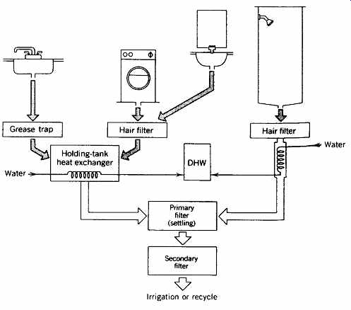
FIG. 54 Sequence of water treatment and heat reclamation for domestic graywater,
where such systems might be approved.
Various stages of treatment are appropriate for different kinds of graywater (FIG. 54). Kitchen sink waste contains grease, which should be trapped (and periodically removed) before it can clog the filters and heat exchangers in a graywater recycling system. Similarly, lavatory showers and laundry waste contain lint and hair that must be intercepted quickly. Devices that do so (called interceptors) were described in FIG. 21.
Currently, building codes tend to sharply limit graywater recycling, generally presume there will be no filtering, and rigidly constrict its use. It is hoped that such restrictions will loosen, with due regard for human health, as conservation of resources becomes more of an imperative than it already is.
(b) Subsurface Irrigation
The 1997 Uniform Building Code (Appendix G), notes that water only from bathroom lavatories, showers and tubs, and clothes-washing machines and laundry tubs, and only in single-family residences, can only be used for subsurface "irrigation" on the same site as the residence. The associated use of mandated trench constructions, as a means of avoiding any surface graywater distribution, may deliver very little water to plants.
Site conditions must meet the requirements of Table 14 and FIG. 55. The bottom of the trenches must be at least 5 feet (1.5 m) above the highest known seasonal groundwater. Flow estimates are as follows:
Number of occupants:
- two for the first bedroom
- one for each additional bedroom
Combined showers, bathtubs, and washbasins, flow per occupant: 25 gal/day (95 L/day) Laundry, flow per occupant: 15 gal/day (57 L/day) A holding tank is required with a minimum 50-gal (189-L) capacity. An unvalved overflow must connect to the building sewer (ahead of any septic tank).
(coming soon) TABLE 14 Location of Residential Graywater System
The irrigation/disposal field must be divided into a minimum of three valved zones (allowing the occupants to better direct flow rates). The total area of this field is the aggregate length of the perforated pipe times the width of the pro posed field. The required area is based on the estimated graywater flow (or size of the holding tank, whichever is larger), based upon the soil types and acceptance rates, as well as the trench design guidelines, shown in Table 15. If percolation tests are performed, the 24-hour percolation rate results must be within these limits:
Minimum, 0.83 gal/ft 2 (33.8 L/m2) Maximum, 5.12 gal/ft 2 (208.5 L/m2) One of several graywater system types from Appendix G of the 1997 Uniform Plumbing Code, is shown in FIG. 56.
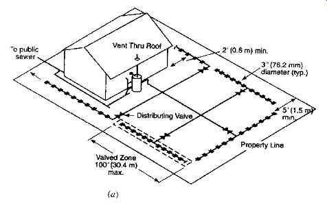
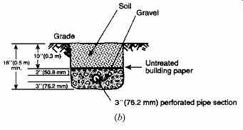
FIG. 55 Example of a residence whose daily graywater flow requires an irrigation/disposal
field (a) using a valved zone as shown in the detail (b). In this example,
five such valved zones are shown (a minimum of three such zones are required).
(Reprinted by permission from the 1997 Uniform Plumbing Code. © by the International
Association of Plumbing and Mechanical Officials, Walnut, CA.)
(coming soon) TABLE 15 Graywater Design Criteria, Six Typical Soils
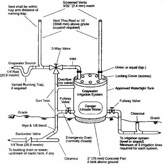
FIG. 56 Schematic diagram of a graywater system with an aboveground, gravity-emptied
tank. (Reprinted by permission from the 1997 Uniform Plumbing Code. © by the
International Association of Plumbing and Mechanical Officials, Walnut, CA.)
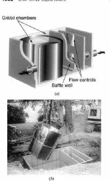
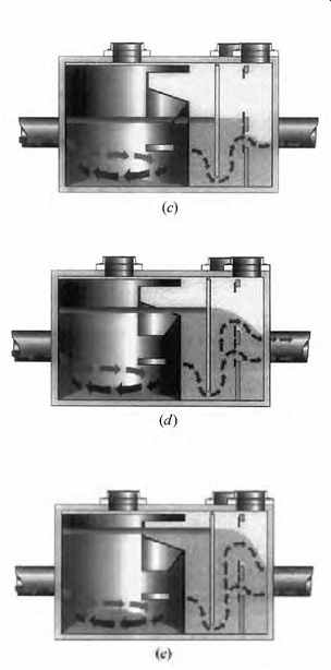
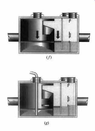
FIG. 57 This Vortechs Stormwater Treatment System (a) is designed to separate
both floating oily contaminants and sediment from storm water. (b) Rather like
a septic tank, two chambers are separated by a baffle. Oil scum and sediment
remain in the first chamber. (c) In a moderate storm, water rises above the
top of the inlet pipe, greatly reducing velocity and turbulence within the
first chamber, encouraging sediment to precipitate to the bottom. (d) As flow
increases, rising above the low-flow control (second chamber), oily contaminants
accumulated from previous storms float upwards, and more sediment falls out.
(e) At the height of storm water flow, usually designed for a 10-year storm,
the high-level outlet begins to discharge. Sometimes a peak flow bypass is
used. Oily scum and sediment continue to be trapped in the manhole. (f) As
the flow subsides, water outflow is controlled, lessening the strain on the
storm drainage system. (g) Cleanout, at the lowest water levels, is best done
by a vacuum truck. As the grit chamber empties, oily liquids and floating debris
drain back toward the inlet and can be removed along with the sediment. Note
that the bottom of the baffle between the chambers always remains submerged.
(Courtesy of Vortechnics Incorporated, Portland, ME.)
10. STORM WATER TREATMENT
Until relatively recently, storm water runoff from buildings and paved surfaces was considered harm less and was conducted without treatment, and as rapidly as possible, to receiving streams, rivers, and lakes. However, almost three-quarters of the U.S. population lives on only about 7% of the land.
And as our urban watersheds become more and more paved and/or roofed, two problems develop.
First, a heavy rain greatly increases peaks in stream flows (because less rain is retained for later, slower release by the action of unpaved surfaces); this accentuated peak-valley pattern of flows makes life more difficult for aquatic flora and fauna. Second, pollutants (especially those accumulated on road ways) are washed into streams; oil, gasoline, anti freeze, fragments of brake linings and tires, and so on are especially unwelcome deposits. Some design strategies to minimize these impacts, such as roof retention, porous pavement, and on-site ground water recharging, were discussed in Section 20.6.
With minimal changes in street design, storm water receptacles can be constructed not only to provide access for maintenance, but also to screen out sediment, capture oil and other floating contaminants, and provide a more even outflow (FIG. 57). But much more can be done.
Phytoremediation is the science of cleaning polluted soil and water with plants. (The constructed wetlands and algal ponds described in Sections 7 and 8 apply phytoremediation to sewage treatment.) Phytoremediation extracts, degrades, or contains contaminants. Plants that extract take up and accumulate contaminants in their shoots and leaves; when the vegetation is removed from the site, so is the contaminant. Plants that degrade break down contaminants (such as hydrocarbons and other organic compounds) until they are no longer toxic. Some plants degrade toxins in their root zone, whereas others use elements of organic toxins as food. Plants that contain essentially immobilize toxins in long-term storage. However, when the plants die and decompose, long-lived toxins may be released. For treating storm water, plants are typically incorporated in drainage strips between paved parking areas. The mix of plants is similar to those cited earlier in wetland construction, with sedges and rushes especially effective at cleansing (see FIG. 2 for a sample trench). Shade trees could add welcome summer thermal benefits, as well as intercepting and storing some pollutants. The capacity of the planting strip should be sufficient to intercept the "first flush" of rain, which carries the heaviest load of pollutants. Underground drains intercept excess runoff and lead to a capture chamber where floatable contaminants can be periodically removed.
The screened, regulated flow from the capture basin will be much gentler on the receiving stream.
A new community in Bellevue, Washington, incorporated a storm water treatment facility in a 20-acre (8.1-hectare) public park. Beneath tennis courts, ballparks, picnic areas, and other playing fields, a 300,000-ft 3 (8495-m3) sediment vault (surface area about 8 acres [3.2 hectares]) slows the flow of storm water, encouraging sediment to drop out. The water then passes to a filter basin of vegetation, sand, and peat for the primary purpose of phosphorus removal. From there it is slowly released to the receiving stream, which then drains into a lake.
Building designers rarely encounter such com munity-wide pollution control strategies, but parking lots and on-site roadways are encountered on virtually every project. Design for local pollution control, even for seemingly benign storm water, is part of the architect's responsibilities.
References and Resources
Composting Toilet World: http://www.compostingtoilet.org/
Converse, J., et al. 1978. Design and Construction Manual for Mounds. Small Scale Waste Management Project, University of Wisconsin Extension.
Madison, WI.
EPA. 1993. Subsurface Flow Constructed Wetlands for Wastewater Treatment. EPA 832-R-93-008.
U.S. Environmental Protection Agency, Office of Water. Washington, DC.
Green, F. B., L. Bernstone, T. J. Lundquist, J. Muir, R. B. Tresan, and W. J. Oswald. 1995a. "Methane Fermentation, Submerged Gas Collection, and the Fate of Carbon in Advanced Integrated Wastewater Pond Systems," in Water Science and Technology, Vol. 31, No. 12.
Green, F. B., T. J. Lundquist, and W. J. Oswald. 1995b.
"Energetics of Advanced Integrated Wastewater Pond Systems," in Water Science and Technology, Vol. 31, No. 12.
Green, F. B., L. Bernstone, T. J. Lundquist, and W. J. Oswald. 1996. "Advanced Integrated Wastewater Pond Systems for Nitrogen Removal," in Water Science and Technology, Vol. 33, No. 7.
IAPMO. 1997. Uniform Plumbing Code. International Association of Plumbing and Mechanical Officials. Walnut, CA.
ICC. 1997. International Plumbing Code. International Code Council. Falls Church, VA.
Ludwig, A. 1997. Create an Oasis with Greywater. Poor Richard's Press. Santa Maria, CA.
Milne, M. 1976. Residential Water Conservation. U.S. Office of Water Research and Technology, Department of Commerce, NTIS. Springfield, VA.
National Small Flows Clearinghouse. 1997. "Lagoon Systems Can Provide Low-Cost Wastewater Treatment," in Pipeline, Vol. 8, No. 2. National Small Flows Clearinghouse. Morgantown, WV.
Nelson, G. 1981. "Graywater Heat Recovery," in Solar Age, August.
Oswald, W. J., C. G. Golueke, R. C. Cooper, H. K. Gee, and J. C. Bronson. 1963. "Water Reclamation, Algal Production and Methane Fermentation in Waste Ponds," in International Journal of Air and Water Pollution, Vol. 7.
Oswald, W. J., A. Meron, and M. D. Zabat. 1970.
"Designing Waste Ponds to Meet Water Quality Criteria," in Proceedings of the Second International Symposium on Waste Treatment Lagoons, Kansas City, MO.
Oswald, W. J. 1990. "Advanced Integrated Waste water Pond Systems," in Supplying Water and Saving the Environment for Six Billion People: Proceedings of the 1990 American Society of Civil Engineers Convention, Environmental Engineering Division, November 5-8, San Francisco.
Oswald, W. J., F. B. Green, and T. J. Lundquist. 1994. "Performance of Methane Fermentation Pits in Advanced Integrated Wastewater Pond Systems," in Water Science and Technology, Vol. 30, No. 12.