AMAZON multi-meters discounts AMAZON oscilloscope discounts
(cont. from part 1)
6. RAINWATER AND SITE PLANNING
Prior to the spread to rural areas of buildings, streets, roads, and paved parking lots, water from rainfall and melting snow found its own way to natural destinations. Surface flow to creeks, streams, and rivers accounted for part of this drainage. Underground flow aided the general runoff. Outcropping of flowing groundwater created springs and artesian wells. Low, dished areas formed lakes that in turn overflowed to outlet streams. Flat areas sometimes developed into swamps or marshes.
At a time when there was a choice of locations for towns and villages, sites next to rivers were usually chosen. The waterways provided transportation, and water was supplied from the river or from adjacent wells. As streets and roads were built, slopes could be arranged whereby the rain falling on these areas and flowing onto them from roofs of buildings could run to the river. At interior parts of the country, high ground was favored for building sites and growing communities. Swampy or marshy ground would not be chosen, but did provide terminal locations for the storm water that ran off the high ground. In the course of this natural flow, much of the water was drawn by evaporation to the clouds. The rest, conforming to topographic river basins, continued to seek its way to the sea.
As building increased, desirable locations grew scarce. The possibility of selecting high, dry ground diminished. Great areas, formerly low and marshy, were filled in and buildings constructed, often on piles. From such locations storm water could not be disposed of by drainage to some adjacent lower area or even recharged to the earth through dry wells.
Moreover, extensive grids of paved streets and side walks in these level developments caught and held the water, resulting in considerable "ponding." Storm sewers had to be built and the water trans ported great distances, often having to be lifted at intermediate pumping stations before reaching its destination, which might be a remote river.
TABLE 6 Some Constituents of Stream Water
This emphasis on the removal of storm water has led to an expensive and elaborate system based on quick disposal of rainfall. By decreasing the time between precipitation and runoff, quick disposal increases the peak flows within such systems, thereby increasing flooding of rivers during storms but reducing the rivers' flow between storms. It also contributes pollutants to waterways that otherwise would have been filtered by the soil, as detailed in TABLE 6.
The overloading of storm sewers not only causes minor flooding, but also can influence building design. The designers of the New Orleans Convention and Exhibition Center, a building with 610,000 ft2 (56,670 m2) of roof area, spared the city's storm sewers from the impact of a 14-acre (5.7-hectare) runoff by carrying the rainwater over the roofs of adjoining wharfs and discharging it directly into the Mississippi River.
As urban storm sewers reach capacity and suburban groundwater levels drop, designers have begun to emphasize storm water infiltration (or recharge of groundwater) rather than quick run off. Three design strategies for encouraging such recharge have emerged: roofs that will retain water and slowly release it, porous pavement, and onsite infiltration of runoff.
(a) Roof Retention
If storm water is to be sent to storm sewers or to soak into the ground, a slow flow from roofs will help by diminishing peak flows in sewers and giving soaked soil more time to absorb still more runoff. A nearly flat roof with specially designed drains (see FIG. 23) forms a temporary pond that permits slower discharge, yet eventually drains completely dry (to discourage mosquito breeding, etc.). (For cisterns, however, sloped roofs should be used, as they stay cleaner than flat roofs.) Another possibility is a sod roof that retains water for longer periods than ponded flat roofs (FIG. 10). Another option is to store the cistern water on the roof itself (FIG. 11).
However achieved, this temporary pond on top of a building will clearly add to structural requirements. Another problem could be posed by high winds blowing sheets of water onto people below.
In summer, however, a flooded roof can provide a significant thermal advantage by greatly lowering daytime roof surface temperatures. Rainfall retaining roofs are now required in some urban areas with overtaxed storm sewers. Sewer districts frequently charge for storm water runoff; by ponding storm water on site, such charges can be reduced or avoided.
(b) Porous Pavement
To retain rainfall on site, many builders use either porous asphalt (FIG. 12), porous concrete, "incremental" paving, or open-celled pavers (alter nation of paving materials with grass or ground cover plants) for parking lots and roadways.
Porous concrete has been used for many years in building construction as a low-strength, high porosity material that has some insulating properties (R-5 for 10-in. thickness [RSI-0.88 for 254 mm]). Patented porous concrete pavement now in use in Florida has a strength of more than 3800 psi (26,200 kPa) and a permeability of 2.3 gallons of water per minute per square foot (94 L per minute per square meter). (A 2500-psi [17,240 kPa] mix has a permeability of 18.5 gallons per minute per square foot [750 L/m per m2].) In cold-weather areas, the freeze-thaw cycle could be destructive to porous concrete.
Incremental paving features many small, adjacent paving units; the resulting many joints allow water to pass through more readily than do solid, unbroken surfaces.
Open-celled pavers alternate small concrete or plastic paving units with grass or ground cover, as shown in FIG. 13. These are particularly applicable to short-term parking, as for a sports stadium, or for more remote areas of retail mall parking lots.
They are also possible for roadway shoulders and emergency vehicle-only access areas.
If storm water is not retained, its runoff can be polluted to the extent that treatment is required. Using strips of planting for such treatment (phytoremediation) is discussed at the end of Section 22.
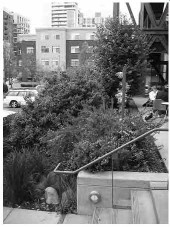
FIG. 10 Bioswale at the Ecotrust building in Portland, Oregon, captures
storm water runoff from the green roof of the building and other surfaces.
(Photo by Nathan Majeski.)
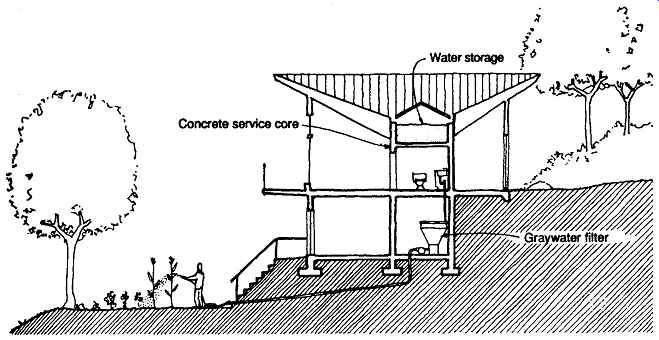
FIG. 11 Retaining rainwater so that gravity flow can encourage its usage.
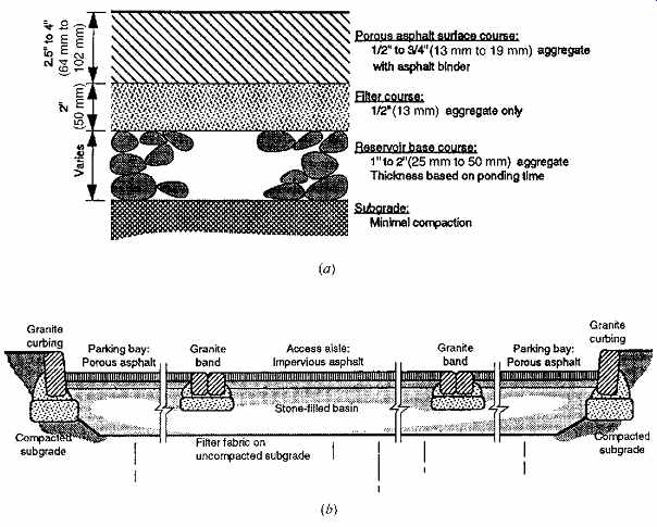
FIG. 12 Porous paving encourages groundwater recharge rather than storm
runoff. (a) Standard porous asphalt pavement as used in Rockville, Maryland.
(b) Subsurface basin allows required retention ponds to serve as parking lots;
this example is at the Morris Arboretum in Philadelphia. (Reprinted by permission
from B. Ferguson. 1998. Introduction to Stormwater. John Wiley and Sons. New
York.)
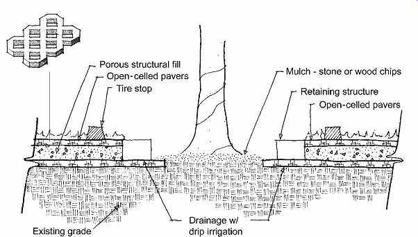
FIG. 13 Open-celled pavers on a porous fill allow grass or hardy ground
cover to grow within the units. (Drawing by Erik Winter of GrassPave from Invisible
Structures, Inc. Information used with permission.)
(c) Site Design for Recharging
This tactic is especially advisable for suburban density developments in drier climates with absorptive soil (sand, gravel, etc.). The first option is at each house; design of entire subdivisions can also be influenced.
The simplest design approach is the gutterless sloped roof illustrated in FIG. 14, which is applicable to one-story, basementless homes with wide, overhanging roofs. A gravel-filled trench skirting the perimeter directly below the edge of the eaves catches the water flowing off the roof.
Some designers do not like the appearance of conventional gutters and leaders; other designers celebrate them (FIG. 15). There are many ingenious ways to avoid or modify their use and yet provide proper drainage. In many cases, however, gutters and leaders will be required, either to collect rainwater for cisterns or to control conditions around the perimeter of a house. Several options for storm water recharge can be used with the gutter leader combination.
A splash pan at the foot of each leader (FIG. 16a) offers the simplest method. It will lead the water a few feet from the house but will accommodate only a relatively low rate of flow. A gravel filled pipe is somewhat more effective (FIG. 16b). When the soil is not very permeable (as, for instance, with clay), it is best to use a dry well with an extended area and many perforations through which the water can be discharged to the ground (FIG. 16c).
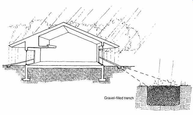
FIG. 14 Gutters and leaders are not always essential, provided that doorways,
walls, foundations, and landscaped lawns are not subjected to rain concentrations.
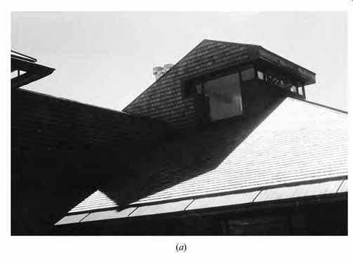
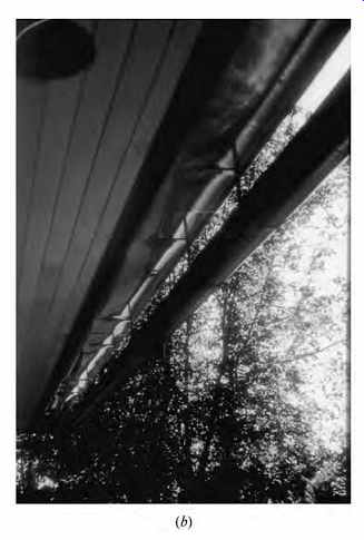
FIG. 15 Falling rain is featured at this Oregon residence, where the gutter
is held below the metal flashing at the roof's edge. Run off is seen from indoors
as it falls into the suspended gutter. (Unthank Poticha Waterbury, Architects,
Eugene, OR.)
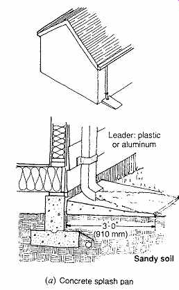
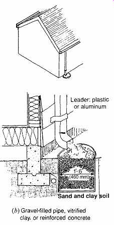
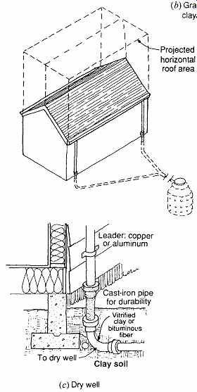
FIG. 16 Roof drainage for houses. Method (a) is suitable for low rates
of flow introduced into very pervious soil. When denser soil is encountered,
method (b) is used to get the water into the ground and thus avoid surface
erosion. For heavy flow or to lead the water farther from the structure, method
(c) may be used with one or several dry wells.
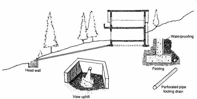
FIG. 17 Disposal of storm water on the site but remote from the house or
building. When a wall is against a hill, it is usually subjected to the pressure
of groundwater during storms. Open-joint clay, plastic, or fiber tile accepts
this water and carries it away. Footing drains are tight-joint clay tile or
bituminous fiber pipe. Flow through stone and gravel returns the water to the
earth. A head wall is appropriate in lieu of a dry well if the site permits.
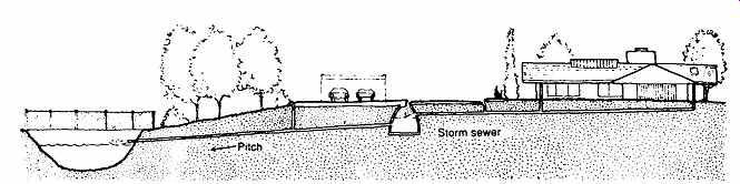
FIG. 18 Recharge basins in suburban communities. When topography, groundwater
level, and porosity of the soil permit, developers are sometimes required to
install systems that collect storm water and carry it from catch basins at
street curbs, the roofs of all houses, and paved areas to a recharge basin
that receives the water and returns it to the ground. For the safety of children,
a fence is sometimes required to prevent unauthorized access to the basin.
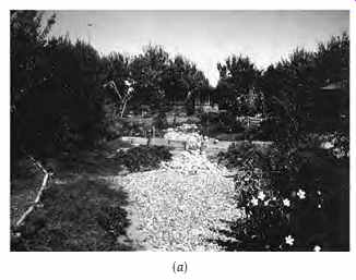
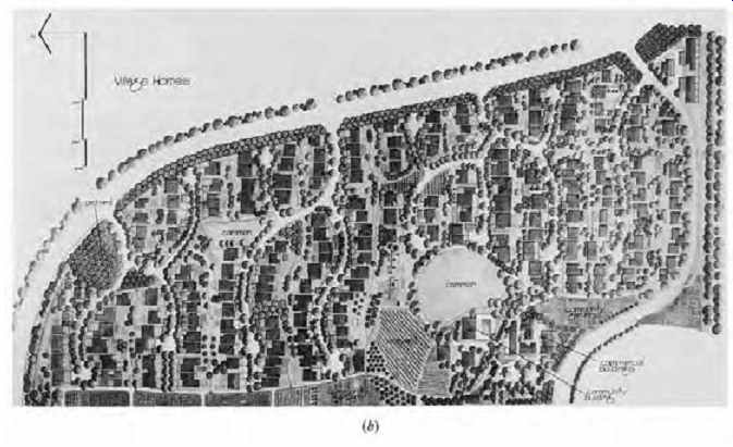
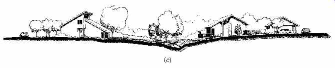
FIG. 19 Village Homes, a northern California subdivision of solar homes
and storm water recharge areas. (a) Photo illustrates the open drainage ways
and pedestrian paths. (Photo by Alan Butler.) (b) Plan shows the emphasis on
bicycle paths, narrow streets, and widespread community-maintained garden space
through which the recharge streambeds are led. (c) Site section explains the
gradual drainage from leaders at houses to recharge stream. (Reprinted by permission
from M. Corbett, A Better Place to Live; © 1981 by the Rodale Press.)
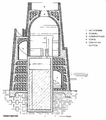
FIG. 20 Section through the observation tower/cistern at the Lady Bird
Johnson Wildflower Research Center. (Courtesy of Overland Partners, architects,
San Antonio, TX.)
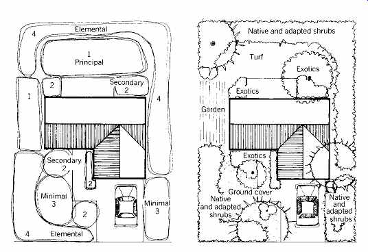
FIG. 21 The hydrozone concept of landscape planning restricts exotic planting
to special, easily watered areas. Native and adapted plantings are used elsewhere.
Hydrozonics are here shown on a typical suburban lot. (Reprinted by permission
from Energy-Conserving Site Design; E. G. McPherson, ed.; © 1984 by the American
Society of Landscape Architects.)
Footing drains are often used to collect and lead away groundwater that accumulates around foundations. This reduces the likelihood of basement wall leakage. These drains are most necessary when higher ground near a building increases the flow of groundwater against under ground walls. Figure 17 illustrates this and also shows how storm water from drains and roofs may be led to a surface absorption area of rock and gravel beyond a head wall where the general storm drain outcrops. This method can be chosen where there is sufficient property area and slope. It has the advantages of easy maintenance and ser vice. Also, one can observe whether it is functioning correctly.
In new suburban developments, for which there are no storm sewers, recharge basins (FIG. 18) are sometimes required to deliver storm water to the ground. Water from numerous roofs, paved areas, and curb catch basins is collected and piped to an open, unpaved pit, where it sinks into the earth. This method is not recommended in areas of dense, impervious clay soil. A particularly effective example of this approach is offered by the community of passively solar-heated residences known as Village Homes, outside Davis, California. This area receives only about 20 in. (about 500 mm) of rain annually, so the recharge of groundwater was to this garden oriented community a far more attractive (and less expensive) option than loss of the rainwater to a storm sewer. Storm water flows from leaders to dry, rockbed channels, along which are gardens and bicycle paths (FIG. 19). Occasionally, small dams across these channels create temporary holding ponds in case the runoff has not yet soaked through the channel bottom.
In the event of extraordinarily heavy rainfall, an inlet to the public storm sewer is available beyond the final holding pond; this inlet is needed approximately once every 5 years.
The National Wildflower Research Center (FIG. 20) is built over an endangered aquifer southwest of Austin, Texas. This complex of small buildings and larger gardens includes two cisterns, one of which forms the base of a central observation tower. Water gardens and irrigation are both served by the cisterns. The buildings' roofs are designed for rainwater collection, and a small channel (aqueduct) carries water over a wall to the outer cistern.
The planning of the landscape around buildings may closely follow such considerations as irrigation. The hydrozone concept of landscape planning is shown in FIG. 21. To minimize water consumption, exotic plant species are kept to a mini mum and located near the house, where storm run off and irrigating water are readily available. Native and adapted plantings, which can survive on normal rainfall, are utilized elsewhere. Landscape that requires no additional water is often called a xeriscape; see a discussion of irrigation systems and an example in California's Napa Valley.
7. COMPONENTS
The first storm water system design decision to be made involves the establishment of "watersheds" on a building's roof. To what edges, or at what points, will runoff be directed? To what depths will it accumulate before it leaves the roof? Because the answers to these questions depend on the intensity of storms as well as on the roof's geometry, it is necessary to find the maximum hourly rainfall for each location. This figure is available from local building code officials, or from Fig. 20.
Gutters and leaders (downspouts) can be sized through the use of Tables 7 and 8.
The sizing of gutters and leaders depends both on the horizontal projected area of the roof, as shown in FIG. 16, and on the maximum hourly rainfall.
EXAMPLE 2
Select a gutter and two leaders for the front half of a house, as shown in FIG. 16. The rainfall rate is 4 in./h (100 mm/h). The projected roof area is 700 ft2 (65 m2) and the slope of the gutter is 116 in. per 1 ft of length ([5.2 mm/m]; 0.5%).
SOLUTION
From TABLE 7, choose a semicircular gutter with a 6-in. (150-mm) diameter. (Note that if a steeper gutter slope were designed, at ½-in. slope per foot (4%), then only a 4-in. (100-mm) diameter gutter would be required.) Because two leaders will be used, each will drain 350 ft2 (33 m2). TABLE 8 shows that a 2-in. (50-mm) leader can be used. For this gutter-leader combination, specify the detail of FIG. 23a.
Storm gutters and leaders can have an important impact on a building's appearance (FIG. 24). Alternatively, leaders can be set within buildings, and gutters can be built into a roof's surface to minimize the visual impact.
Where routing of storm water inside a building is preferable, drains and leaders can be sized from TABLE 8, and horizontal piping can be sized from TABLE 9. Care should be taken to insulate such lines; cold rainwater inside pipes can cause condensation to form on the outside pipe surface, sometimes resulting in staining and other water damage.
EXAMPLE 3
Select the sizes for vertical conductors and horizontal storm drains for the building shown in FIG. 25. The roof, balcony, and courtyard areas are as shown, the rainfall rate is 4 in./h (100 mm/h), and the pitch of horizontal drains is ¼-in. slope per 1 ft of run (2%; approximately 20 mm/m).
SOLUTION
The sizes selected and shown in FIG. 25 may be verified in Tables 8 and 20.
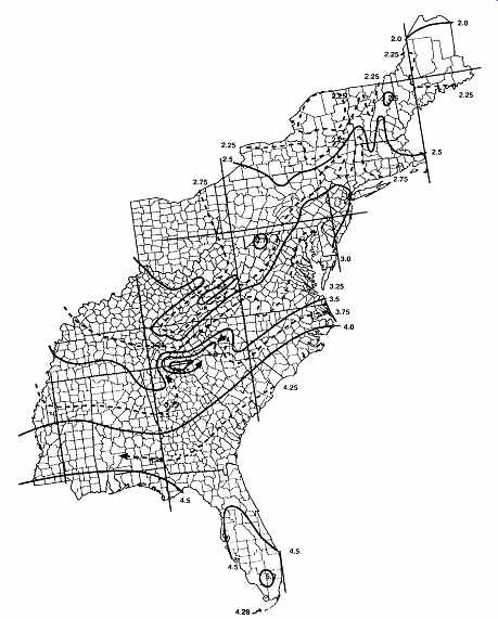
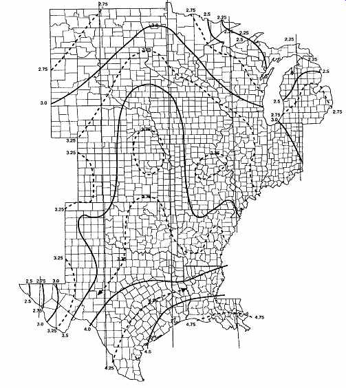
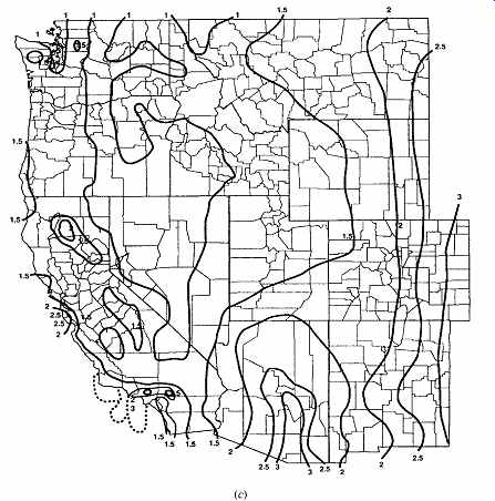
FIG. 22 Maximum 100-year, 1-hour rainfall (in inches). (a) eastern United
States; (b) central United States; (c) western United States.
(Note: Alaska, range 0.4 to 1.4 in. [10 to 36 mm]; Hawaii, range 1.5 to 8 in. [38 to 203 mm]) (International Plumbing Code. Reprinted with permission. All rights reserved. 1997, International Code Council, Inc., Falls Church, VA.)
TABLE 7 Size of Gutters (coming soon)
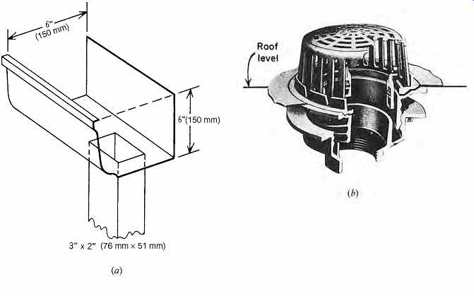
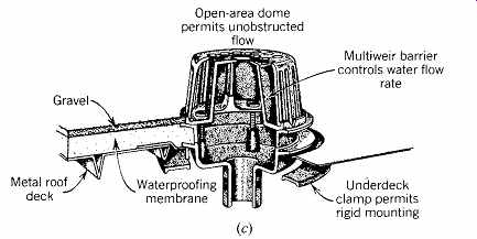
FIG. 23 Storm drainage components. (a) Conventional gutter and leader for
houses; sizes vary by manufacturer. (b) Ordinary roof drain (Josam Manufacturing
Co.). (c) Roof drain for controlled flow. (From Specifying Engineer, November
1982.)
TABLE 8 Sizing Roof Drains, Leaders, and Vertical Rainwater Piping (coming soon)
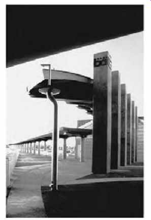
FIG. 24 A downspout terminates the roof with flair at the Pleasanton BART
(Bay Area Rapid Transit) station near San Francisco. (Photo by Jane Lidz.)
TABLE 9 Sizing of Horizontal Rainwater Piping

FIG. 25 Separate storm drainage. Areas drained and corresponding sizes
of vertical leaders and horizontal drains are from Tables 8 and 9. Storm
drain piping within a building needs insulative covering with a vapor retarder
on the outside. This prevents condensation (sweating) on the pipes when, in
winter, warm, moisture-laden air in the building could otherwise reach the
pipe surface (which would be cold from carrying icy water), condense there,
and lead to wet, dripping conditions on the pipes. Each roof has two drains
in case one is temporarily blocked. (Drawing by Nathan Majeski.)
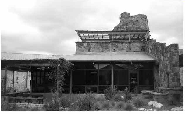
FIG. 26 Lady Bird Johnson Wildflower Center in Austin, Texas; view to the
Visitor's Center. (Photo by Jake Moore; 2009 Alison Kwok; all rights reserved.)
8. CASE STUDY-WATER AND BASIC DESIGN
Lady Bird Johnson Wildflower Center, Austin, Texas
PROJECT BASICS
• Location: Austin, Texas, USA
• Latitude: 30.18 N; longitude: 97.89 W; elevation: 621 ft (189 m) Austin city.
• Heating degree days: 1688 base 65ºF (938 base 18.3ºC); cooling degree days: 7171 base 50ºF (3984 base 10ºC); annual precipitation: 30 in. (762) per year
• Building type: New construction; offices, visitor's center, classrooms
• 54,000 ft2 (5017 m2)
• Completed 1995
• Client: LBJ Wildflower Center
• Design team: Overland Partners and consultants
Background. The Lady Bird Johnson Wildflower
Center is an award-winning project that exemplifies resource conservation through a careful union between landscape and buildings. Elements of the design process for water conservation and other strategies at the Wildflower Center are presented in the discussion that follows, in order to emphasize the importance of an integrated design process to redevelop a native landscape and to showcase the intrinsic beauty of local materials.
The client's values were important to the success of this project-to realize a 13-year campaign to bring research and resources together on behalf of native plants. It has become a place to learn about native plants and how to reduce water consumption while maintaining a beautiful outdoor habitat.
Initially named the National Wildflower Research Center, founded by Lady Bird Johnson and actress Helen Hayes in 1982, the Center has expanded beyond its original intentions to incorporate education, progressive environmental movements, and the publication of data on landscaping with native plants in the United States. To accommodate its success and growth, the Wildflower Research Center moved to a new site in 1995. In 2006, the Wildflower Center became an Organized Research Unit of The University of Texas at Austin's College of Natural Sciences and School of Architecture.
Concern for water conservation led to many of the distinctive forms seen in the cisterns and water ways on the land. (The information that follows was provided by Overland Partners.) Context. The Lady Bird Johnson Wildflower Center is a research center designed to share information with the public by increasing awareness and under standing of local native plants and landscapes. In 1997, the Center was renamed the Lady Bird John son Wildflower Center and its mission expanded to include educational opportunities for visitors.
Within the last decade the Center has played an active role in land restoration, plant conservation, the Millennium Seed Bank Project, and the creation of the Sustainable Sites Initiative in conjunction with the American Society of Landscape Architects.
Design Intent. The mission of the Wildflower Center is to: "increase the sustainable use and conservation of native wildflowers, plants and landscapes." Aligned with this, the design of the Center teaches by example with particular attention being given to the visitor's experience. Rather than creating one monolithic building, the project comprises several smaller buildings wrapped by landscaping, demonstration gardens, and a main plaza. Orientations of these buildings frame views of the terrain and extend the notion that the Center is more about the landscape than the buildings. A key element of the design was to eliminate the need to pump water from the endangered Edwards Aquifer.
Many of the native plants help conserve water, since they require little water. Rainfall from building rooftops drains into various cisterns and storage tanks to be used later for irrigation. Some rooftops are connected with aqueducts that allow the water to flow to a shared storage tank/cistern.
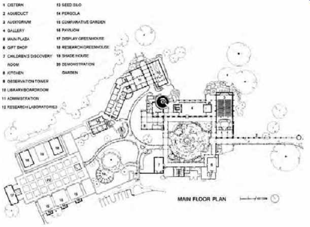
FIG. 27 Site plan shows two cisterns, one at the far right (1), the other
in the central observation tower (9). 1. Cistern; 2. Aqueduct; 3. Auditorium;
4. Gallery; 5. Main plaza; 6. Gift shop; 7. Children's discovery room; 8. Kitchen;
9. Observation tower/cistern; 10. Library/board room; 11. Administration; 12.
Research laboratories; 13. Seed silo; 14. Pergola; 15. Comparative garden;
16. Pavilion; 17. Display greenhouse; 18. Research greenhouse; 19. Shade house;
20. Demonstration garden. (Overland Partners Architects; used with permission.)
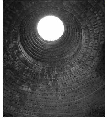
FIG. 28 Oculus of the water tower cistern. The tower serves as a focal
point for views of the site.
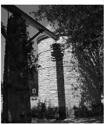
FIG. 29 Entry cistern fed by aqueducts from the site's rain water harvesting
system.
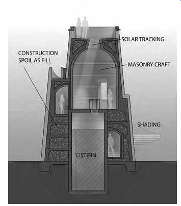
FIG. 30 Section of the tower cistern. (Overland Partners Architects; used
with permission.)
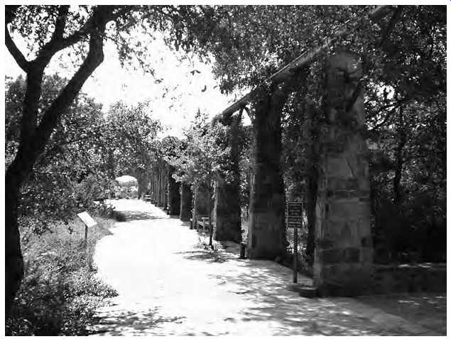
FIG. 31 Rainwater harvesting system on locally-sourced stone arches along
the entry path surrounded by oak trees.
The leading principles behind the design were as follows:
• The building and programs support "total resource conservation."
• Respect existing native wildflowers, landscaping and plants.
• Harmonize built form with landscaping.
• Minimize the impact of the built environment.
• Enable visitor education through example.
• Eliminate the need to pump water from the endangered Edwards Aquifer.
• Respect and utilize the local vernacular, materiality, and craftsmanship.
• "Demonstrate an ecologically sensitive approach to the development of a site with fragile environmental conditions."
• Utilize and design sustainable technologies to aid in conservation efforts.
Design Criteria and Validation. The project was built in 1995, long before the Leadership in Energy and Environmental Design (LEED) certification process. In retrospect, the project complies with many of the principles that guide the LEED rating system. Sustainable design was desirable to maintain the Center's founding philosophies and the ethics of the design team, which were the driving forces behind the environmental design decisions. The intentions of the project were to demonstrate an ecologically sensitive approach to the development of a site with fragile environmental conditions and integrate the buildings and programs to support "total recourse conservation" while showing the beauty of the native landscape and supporting over 400 native plant species.
Post-Occupancy Validation Methods. The success of the Lady Bird Johnson Wildflower Center resulted in more than 20 international, national, state, and local awards for its facilities, programs, and leadership in environmental design. It was calculated that the investment made in creating these facilities brought returns of more than $11 million in free media in the first two years.
Based on the collected data, energy simulations were run using ENER-WIN--a software package used to analyze total building energy performance, developed in the Department of Architecture at Texas A&M University as part of the Vital Signs Curriculum Project. The overall energy performance of the building simulated by this soft ware was calibrated to the actual building energy use based on utility bills for one year. The components of the energy usage were broken down and compared, to see the percent contribution to the HVAC load of the various design features such as use of daylighting strategies and a matching of HVAC and occupancy schedules.
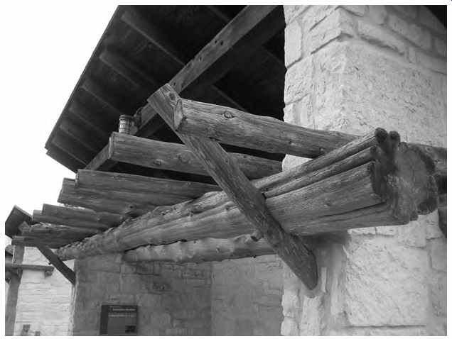
FIG. 32 Wood was reused from the site to create overhangs and trellises.
Performance Data.
• With an average rainfall of 30 in. (762 mm) per year, the whole rooftop system can collect approximately 300,000 gallons (1,135,500 L) of rainwater per year.
• In total, the Center collects water from 17,000 square feet (1579 m2) of roof space and can store more than 60,000 gallons (227,100 L) in on-site cisterns and storage tanks, providing approximately 10 to 15% of the Center's yearly water needs for irrigation and landscaping
• Approximately 10,600 gallons of water per inch of rain (1580 L/mm) are collected for the whole center.
• Five cisterns are used in total, with an approximate capacity of 65,000 gallons (246,025 L): two cisterns at 20,000 gallons (75,700 L) each, one at 5000 gallons (18,925 L), the entry cistern at 12,000 gallons (45,420 L), and the children's "little house" cistern holding 3000 gallons (11,355 L).
• The entry collection cistern system is fed by 1167 ft 2 (108 m2) of metal roof to a 12,000-gallon (45,420-L) cistern. This cistern can collect 7000 gallons per inch (1043 L/mm) of rain, or approximately 21,000 gallons (79,485 L) per year.
• The children's area cistern collects water from 672 ft2 (62 m2) of roof, and has a 3000 gallon 11,355-L) capacity. With approximately 420 gallons per inch of rain (63 L/mm), it can collect 12,600 gallons (47,691 L) of water per year.
• All cisterns are located above ground except for the transfer station, which is under ground.
• Recycled materials included wood flooring and on-site non-biodegradable construction spoil used to fill the tower structure. Local stone, wood flooring, and site boulders were obtained from within a 150-mile (241-km) radius from site.
The project received the following awards and citations: 1995:
Texas Society of Architects-Honor Award
Austin Commercial Real Estate Society-Good Egg Award
Associated Builders and Contractors Awards- First Place for Excellence in Construction 1996:
Recycling and Education Awareness Citations by Keep Austin Beautiful
Good Steward Award by the National Arbor Foundation
American Society of Landscape Architects- San Antonio Design Honor Award
American Society of Landscape Architects- State of Texas Design Honor Award
American Society of Landscape Architects--National Design Honor Award Associated General Contractors--San Antonio Design Honor Award Associated General Contractors--Regional Honor Award
Associated General Contractors-Dallas Section Summit Award
Associated General Contractors-National Design Honor Award
American Institute of Architects-San Antonio section Design Honor Award 1998:
Business Week/Architectural Record-Award Semi-finalist 2000:
American Institute of Architects Committee on the Environment-Earth Day 2000 Top Ten
FOR FURTHER INFORMATION
Overland Partners Architects: overlandpartners.com Lady Bird Johnson Wildflower Center: wildflower.org Rocky Mountain Institute, Green Developments CD, version 2.0, 2001.
References and Resources
Brown, G. Z., J. Reynolds, and S. Ubbelohde. 1982.
InsideOut: Design Procedures for Passive Environ mental Technologies. John Wiley & Sons. New York.
Corbett, M. 1981. A Better Place to Live. Rodale Press. Emmaus, PA.
Ferguson, B. 1998. Introduction to Stormwater. John Wiley & Sons. New York.
Gleick, P. 1998. The World's Water. Island Press. Washington, DC.
International Association of Plumbing and Mechanical Officials. 1997. Uniform Plumbing Code. Walnut, CA.
International Code Council. 1997. International Plumbing Code. Falls Church, VA.
McPherson, E. G. (ed.). 1984. Energy-Conserving Site Design. American Society of Landscape Architects. Washington, DC.
Milne, M. 1976. Residential Water Conservation. U.S. Office of Water Research and Technology, Department of Commerce, NTIS. Springfield, VA.
U.S. Environmental Protection Agency. 1975.
Manual of Individual Water Supply Systems. Washington, DC.
U.S. Geological Survey, Water Resources of the United States: http://water.usgs.gov/