AMAZON multi-meters discounts AMAZON oscilloscope discounts
For some designers, the last building distribution system considered is the one involving the bulkiest items: the flow of supplies in and solid waste out. Because this system usually is not seen as consuming building energy or requiring specialized equipment, it ordinarily becomes a low-priority system in the design process. Yet provisions for delivery of supplies, and especially for the collection and storage of solid wastes, can be more space-consuming than water/waste systems, can present a fire danger, and can create serious local environmental problems. The separation of solid waste for resource recovery involves significant energy and environmental consequences. Finally, mechanical equipment associated with solid waste is now commonly part of waste management systems.
1. WASTE AND RESOURCES
Since the late 1940s, there has been a marked increase in the amount of packaging material used for consumer products. Where shoppers once refilled reusable containers for bulk supplies at the market, for example, they now buy food in bags or cans that are discarded after use. This trend has increased space demands in the store, where shelves of cans are required instead of a bin of bulk products, as well as in the home, where such packaging soon turns into waste and must be stored until garbage collection day. Energy is required to make the boxes, bags, cans, and other containers; transport them; and collect them as trash. Devices such as trash compactors add both space and energy requirements to the use/disposal process. Landfills for garbage disposal are filling rapidly as solid waste flows increase. Methane and leachate from these landfills are potential environmental problems.
There may not be much that building designers can do about these increased packaging trends. But the solid wastes from buildings contain important resources, and a designer can help society to recover those resources rather than burying them in landfills or dumping them in the ocean. Furthermore, buildings themselves can be designed for construction materials recovery upon remodeling or demolition.
TABLE 1 Typical Recyclable Materials from Building Operations (coming soon)
TABLE 2 Solid Waste Sources in Building Operation (coming soon)
The resources within solid waste can be divided into the high-grade resources represented by recyclable materials and the low-grade resources of heat and by-products obtainable from the burning or decomposing of combustible solid wastes.
(a) High-Grade Resources
These include metals such as aluminum and steel, paper and paperboard, wood, and some plastics. For building designers, these pose the problem of storage while awaiting collection. For many of these materials, reuse in their present form is desirable, which eliminates compaction as a storage strategy.
TABLE 1 (coming soon) compares uncompacted and compacted volumes of various recyclable materials.
Glass is especially suitable for recycling when it can be reused after simple washing, as in the case of beer and soft-drink bottles. Returnable (for deposit) bottles and cans have measurably decreased road side litter in states that require such containers.
Newspaper is so readily stored and recycled that in many communities, charitable groups or service organizations recover newspapers for profit. Recycled paperboard can easily save 50% of the energy that would be required to produce pulp from virgin material.
The recovery of aluminum saves 96% of the energy necessary to process it originally. Because the aluminum production process is dependent upon electricity, the recycling of aluminum is doubly attractive. Energy conservation in aluminum production had developed to the point that only 82% as much energy was needed to make a pound of aluminum in 1982 as in 1972. More than a third of that reduction was attributable to aluminum-recycling programs; the remainder came from improvements in the production process. As for steel, recycling can produce a 52% energy savings compared to the use of virgin material.
Wood has become more valuable as fiber than as fuel. Wood chips and scraps that once were burned or buried are now recycled to become oriented strand board (OSB) used in structural insulated panels (SIPs), window frames, and many other aspects of building and furniture construction.
Plastics are more difficult to recycle. Regulations and consumer preferences discourage the use of recycled plastics in food-related items. The plastics from items such as soft-drink containers, margarine tubs and lids, and milk jugs, however, can be reprocessed into plastic pellets, which are cheaper than virgin plastic pellets. These pellets are then made into nonfood items-toys, building products, sports products, and other things.
(b) Low-Grade Resources
These resources include materials for which recycling is impractical but that are combustible. Low grade resources include gaseous wastes, liquid and semiliquid wastes, and solid wastes. Industrial and commercial processes can generate wastes of all types, including some with very high heat content and some that are very toxic. Although recovering heat by burning such materials seems better than landfilling them, air pollution regulations have severely restricted simple trash burning as a means of solid waste disposal. Incinerators must meet increasingly strict regulations and, as a result, are very rarely installed in buildings. A better option is often to compost such materials in landfills. The methane generated in landfills can then be used as a high-grade fuel.
Where large quantities of mixed trash, garbage, and other refuse are collected, special resource recovery plants can be built to recover materials, produce useful steam for electricity generation, and reduce the flow of waste to landfills. In this energy intensive process, mixed garbage is shredded and blown through large "air classifiers" that separate the organic (burnable) wastes from metals and glass. The burnable wastes are then used as fuel, under controlled combustion, to generate electricity. The metals are further separated magnetically into ferrous and nonferrous classes; these and the glass are then recycled.
The Energy Efficient Resource Recovery (E2R2) integrated infrastructure facility that was proposed for California Polytechnic State University, San Luis Obispo, combining waste water treatment and solid waste processing, was introduced in Fig. 22.43. The solid waste facility is shown in FIG. 1.
The schematic design for solid waste processing (SWP) in the proposed E2R2 facility involves trans porting unsorted solid waste to a central processing facility located on campus. Materials will then be sorted using mechanical equipment and processing. The composition of the solid waste stream is expected to be 70% organic materials, suitable for composting, and 815 tons (739 Mg) per year of recyclable materials (i.e., metals, glass, paper, and cardboard). Roughly 10% of the solid wastes are anticipated to be unsuitable for either recycling or composting. These "inert" materials will be disposed of at the local landfill.
Once separated, the design calls for the non-recyclable, organic materials to be uniformly ground and combined with sludge (from the city of San Luis Obispo's wastewater treatment plant) or manure (from the university's farming operations)
to achieve a proper carbon-to-nitrogen balance.
Given the dynamic nature of the recyclable materials market, it is anticipated that, at times, some potentially recyclable paper will be included in the compost operations.
After mixing, the organic materials will be loaded into a high-solids anaerobic digester to undergo methane fermentation. The biogas generated by the fermentation process will be harvested and stored on site. Prior to use, the biogas will be scrubbed (processed) to remove impurities, making it suitable for use as fuel. A portion of the methane will be used to heat the digester, and the excess will power a micro fuel cell to generate electricity for campus use. Other potential uses include using methane in the campus boiler, as an alternative to gasoline in the university's automobile and truck fleet, and even to power an ultra-high-temperature hazardous waste disposal system.
The anaerobic digestion process is projected to generate 180,000 ft 3 (5098 m3) per day of biogas.
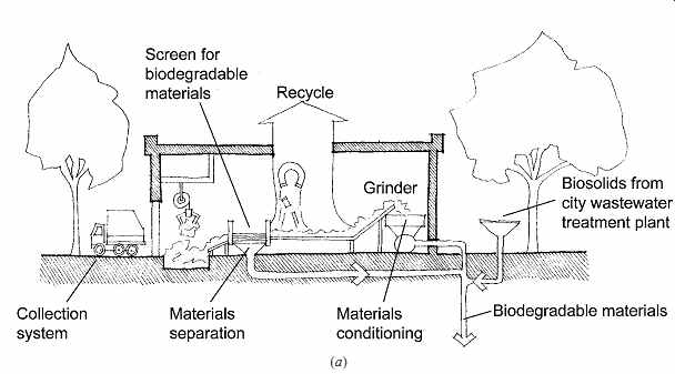
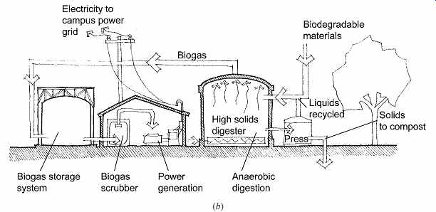
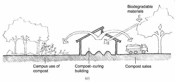
FIG. 1 Schematic design proposal for solid waste processing at the proposed
E2R2 facility at California Polytechnic State University, San Luis Obispo,
California. Unsorted solid wastes are separated into recyclable, organic, and
inert materials (a). The organic materials are ground, combined with sludge
from the city's sewage treatment plant, and loaded into the high solids digester
(b) to undergo anaerobic fermentation. The biogas generated by the fermentation
process is scrubbed to remove impurities from the methane, making it suitable
for use as a fuel to heat the digester and to power a micro fuel cell to generate
electricity for the campus. Biosolids from the digester are pressed, and the
liquid, rich in anaerobic bacteria, is then used to inoculate the next anaerobic
fermentation cycle. Pressed biosolids are mixed with nutrient-rich algae from
the adjacent wastewater facility and pasteurized in compost-curing buildings
(c). Once cured, the compost can be used on landscaped areas or farm lands
or sold to local gardeners. (Courtesy of Professor Douglas Williams, Agricultural
Engineering Department, and Professor Daniel Panetta, Architecture Department,
Cal Poly, San Luis Obispo. Redrawn by Dain Carlson.)
The energy content of the methane in this biogas is estimated at 35 × 109 Btu (36.9 × 10⁹ kJ) per year.
After being unloaded from the high-solids digester, the remaining biosolids will be pressed to recover bacteria-rich liquids, which are useful in inoculating the next batch of materials for the digester. The dewatered biosolids will then be mixed with algae from the adjacent AIWPS (Advanced Integrated Wastewater Pond System) facility to create a nutrient-rich compost. This compost will be available for use on the campus's landscape and its farm lands or for sale to local gardeners. Yearly compost production is anticipated to exceed 5000 tons (4535 Mg) air-dried weight.
As an added touch, straw bale construction is proposed for the E2R2 facility buildings. Currently, plans call for an education and laboratory building, a shared control office for wastewater treatment and solid waste processing operations, a solid waste processing building, and on-site student housing.
Straw bale construction is advantageous because of its affordability, as well as its exceptional insulation and noise mitigation characteristics. In addition, using rice straw for construction will help provide an alternative to burning waste straw from California's rice crop.
Conventional landfills accept unsorted garbage from a huge variety of sources. Over many years, anaerobic combustion in such enclosed land fills generates methane gas, a usable resource, as described previously. FIG. 2 shows an architectural opportunity for such landfill sites: a green house heated by burning landfill (methane) gas.
Electricity generated by landfill gas powers the lighting for the greenhouse. As a design guideline, a site with 1 million tons (907,000 Mg) of refuse in place should produce enough low-heat-value "landfill gas" to support a cogeneration system that includes a greenhouse. Landfill gas, rather than natural (pipeline) gas, can also drive a fuel cell.
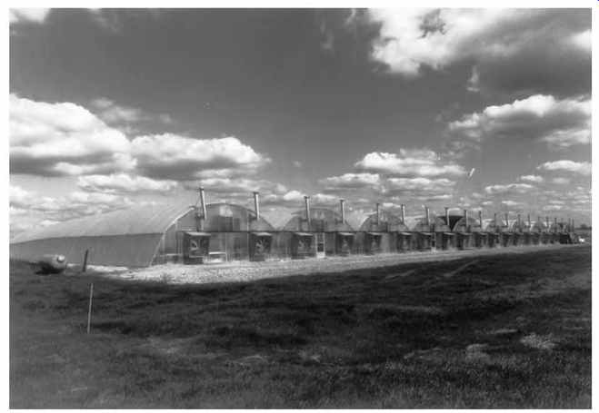
FIG. 2 A 45,000-ft 2 (4180-m2) greenhouse built over part of a 70-acre (28-hectare)
Michigan landfill utilizes "landfill gas" (including about a 65%
methane component) both to fuel space heaters and to generate electricity for
lighting. Waste heat from the generator also contributes to space heating.
(Photo by George P. Graff. Courtesy of Willow Run Farms, Inc., Ypsilanti, MI.)
2. RESOURCE RECOVERY: CENTRAL OR LOCAL?
In general, the more thoroughly mixed the different types of solid waste, the harder it is to recover their high- and low-grade resources. From an energy conservation viewpoint, solid wastes should be kept as separate as possible; glass bottles should be washed and reused rather than broken and recycled, and unrecyclable but burnable solid wastes should be kept clean and dry until they can be burned or composted. The earlier that different types of metals are separated, for example, the less energy spent later on to separate aluminum from steel, and so forth. Organic food wastes could be composted for use on site rather than ground up and added to the load on the sewage treatment system.
There are two disadvantages, however, to local solid waste separation (at the point of their discard)-one cultural, one physical. Keeping solid wastes separate requires somewhat more effort and time on the part of the consumer. Rather than dumping everything in a garbage can, the resource conscious consumer will take the time to understand the local recycling procedures and separate garbage and recyclables in accordance with such requirements. Composting in urban apartments presents a unique space-odor challenge.
TABLE 3 Space Planning for Solid Waste (coming soon)
This disadvantage of slightly more work and time for waste separation is compounded by the physical disadvantage of the floor or cabinet space taken up by multiple containers. In communities fortunate enough to have recycling-oriented garbage service, these containers can be carried out and lined up to await garbage collection. The garbage trucks used for this purpose are complex assemblages of various bins rather than one massive cavern with a compactor. In many communities, however, each pile of recyclable material at home must be dealt with separately, either collected by a specialized handler (nonprofit agencies, for example) or taken to a different collection point-a disadvantage in terms of both the time and energy used in transportation. Clearly, the designer's incentive to include recycling in building function will be stronger where recycling collection is well established.
The characteristics of local waste separation, then, are increased consumer time and building space requirements. Central waste separation is characterized by energy intensive (and noisy) industrial processes. Sections 3 and 4 offer a detailed look at the consequences of local waste separation for some common building types.
The massive quantities of solid waste generated in urban areas give rise to the terms urban mines and urban forests. To the extent that these solid wastes can be turned into resources, savings can be realized: of energy in transportation, of land area for landfills, and of virgin materials replaced by these recycled resources.
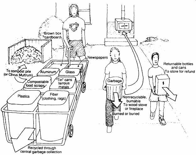
FIG. 3 Local separation of solid wastes can require many containers. In communities
that offer recycling garbage collection service, the consumer can recycle without
transporting individual containers to many different collection points. Some
recycling services ask for glass to be separated into green, brown, and clear
types; some offer to recycle white paper.
3. SOLID WASTE IN SMALL BUILDINGS
The choice between separation of waste or the mixing of garbage in one can is most often enjoyed by the occupants of small buildings. Where food preparation is involved, as in residences or restaurants, the collection of special containers can reach surprising complexity (FIG. 3).
As the point of origin for so many types of solid waste, the kitchen is often the location of waste separation and storage. There is an inherent conflict, however, between the kitchen's frequently hot, humid environment and the need for a cool, dry, well-aired place for solid wastes. This suggests that a space-pantry, air-lock entry, cabinet, or closet- should be provided that opens to the kitchen on one side and to the outside on the other ( FIG. 4). Both the daily depositing of solid waste and weekly waste removal are made easy, and the near-outdoor conditions are better for the waste in many climates. It is also important that cleaning of the waste storage area be easy.
(a) Garbage Disposer
This common appliance ( FIG. 5) is usually installed below the kitchen sink, often in conjunction with a dishwasher. It grinds up organic food scraps and sends them on to the sewer. This device is a boon to central garbage collection because it lightens the weight of the garbage can and adds less moisture to the garbage (which thus can be burned more efficiently). Finely chopped organic matter has a better chance to biodegrade at the wastewater treatment plant than in a tightly packed landfill.
However, garbage disposer units require both water and energy. Water must be kept running during the grinding process to coagulate grease for chop ping, wash the blades and keep them free of debris, and cool the grinder's motor. In all, 2 to 4 gal (7.5 to 15 L) are required for 1 minute of operation.
Because more water and solid waste are deposited in the sewer system, moreover, the central sewage treatment plant requires more energy to operate.
(b) Garbage Compactor
In some small buildings, this device allows for a much less bulky storage arrangement. Used selectively, it can compact several of the stacks of items shown in FIG. 3, such as aluminum for recycling, ferrous metals, and box cardboard. Used indiscriminately, it can make the central process of garbage separation more difficult by crushing dissimilar items together. For a recycling-conscious single family household, it is questionable whether a compactor will save much more storage volume than it takes for itself. However, small stores and institutions with large quantities of a bulky waste (such as cardboard) could save considerable storage space.
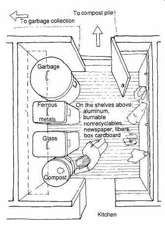
FIG. 4 An entry vestibule (or airlock) to a kitchen can serve as a depository
for solid wastes, as well as for coats, boots, and other items. Heavy, dirtier
items belong on the floor, and many recyclables can be readily and conveniently
stored on shelves.
An outdoor hose bibb is useful for washing out soiled compost containers and garbage cans.
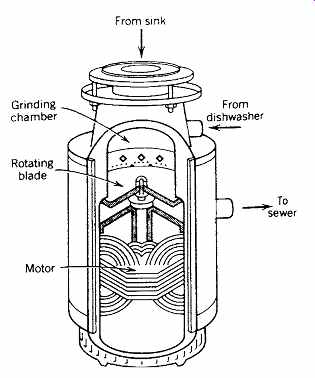
FIG. 5 The garbage disposer (or grinder) diverts solid waste (food scraps)
from landfills to sewage treatment plants.
Occupying very little space, it saves garbage storage space and some of the user's time, but it requires more energy and much more water than treatment of the food scraps as garbage.
Composting is another alternative.
(c) Compost Pile
An alternative to a resource-hungry garbage disposal is the compost pile, familiar to most home gardeners as a source of excellent soil conditioners.
Urban opportunities for composting seem very limited; yet, raised growing beds on a balcony or window flower boxes are logical recipients of a family's compost. The problem may not be so much what to do with the final product (humus) as where to locate the compost pile. Several self-contained composting containers are commercially available.
The outdoor compost pile has several characteristics that challenge the designer. At its best, it is a frequently turned, quite warm, damp, well-aired source of rich humus (and red worms) for gardens; odors are noticeable only while the pile is turned.
At its worst, it is a source of unpleasant odors, a breeding place for vermin, and a fast-food attraction for rats, dogs, and raccoons. Where odors are not objectionable, the heat generated in a frequently fed and tended compost pile might be welcome against the exterior walls of a residence. Clearly, these walls must have nonorganic exterior materials.
(d) Storage Areas
As groups of residences are combined into large apartment complexes, the necessary solid waste systems can make more significant demands on the designer. Approximate exterior storage areas are listed in TABLE 3. Where central storage com pounds are provided, garbage cans should be fenced to ward off dogs and other marauders. Different bins for recyclable materials might be provided.
Where space is limited, a single bin could accept specific materials on designated days-newspapers on Mondays, metals on Wednesdays-if collection schedules permit. A central compost pile could pro vide humus for site landscaping. (An incinerator, used to recover heat from non-recyclable burnable wastes, is almost never approved for installation today.) This combination of space and equipment has special environmental needs, including garbage truck access, noise control, and location of both incinerator stacks and the compost pile with respect to prevailing winds.
4. SOLID WASTE IN LARGE BUILDINGS
In large buildings, it becomes more likely that solid wastes will be handled several times during the storage and collection process. This may inhibit the separated-waste approach because not only the employees who generate the waste, but also the custodians who collect and store it, must understand what items go into which bins. Larger buildings, however, tend to generate large and concentrated kinds of wastes, which makes recycling more attractive while also increasing the demand for storage space.
Consider the multistory office building. Office operations are likely to discard large quantities of white paper and smaller quantities of newspaper, box cardboard, and unrecyclable burnable trash (including floor sweepings). Much smaller quantities of food scraps (coffee grounds), metals, and glass are also generated. Given the high cost of floor space, the pressures are very high for a simple mixed-garbage can (rather than multiple separate bins). However, the cost of hauling trash to increasingly scarce landfills is now so high that many recycling programs pay for themselves both by avoiding landfill charges and by the value of recycled materials.
(a) The Collection Process
In larger buildings, the collection of solid waste is typically a three-stage process (FIG. 6). The first stage is the generation of the waste itself by employees who might be provided with one wastebasket each. If each employee is expected to separate wastes, this suggests a redesigned receptacle. At the typical desk in an office building, white paper, recyclables, compostable materials, and garbage would be deposited in separate compartments. Waste separation at the point of origin thus may not require much more floor area, just more attention by the worker.
The second stage begins as custodians work with these individual baskets, dump them into separate bins on a collection cart, and reconnect the individual empty baskets for the next day's deposits. At various stations, special wastebaskets can be supplied: for white paper at the computer room and the copying machine, for compostable materials and garbage at the employee lounge. Floor sweepings are added to garbage. When the collection cart is full, it is wheeled to a service closet, which is probably located within the core of the building.
Here there is a container for each category of waste, along with a service sink to wash out the garbage bin (and perhaps a paper shredder to be used selectively by employees).
The third stage begins at the ground floor of the service elevator, where white paper and other recyclables are perhaps shredded and stored until collection; compostable materials are stored or sent to a roof garden compost pile; and garbage is compacted and bagged. In the storage space, a cool, dry, fresh air supply is desirable. A sprinkler (fire protection) system is often required. The compactors and shredders are noisy and must be vibration-isolated from the floor. At the end of the third stage, a truck or van from a recycling center collects recyclables, and a garbage truck collects garbage bags.
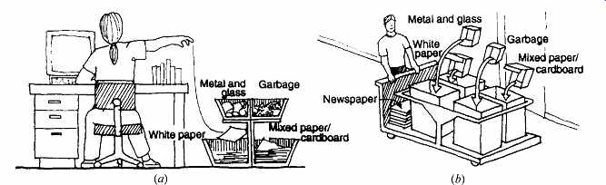
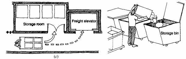
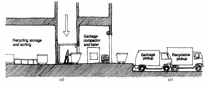
FIG. 6 Hypothetical three-stage solid waste collection process with four-category
separation for office buildings. (a) At each work station, a four-compartment
waste receptacle is provided. White paper is the predominant waste product.
(b) Custodians begin the second stage by collecting waste in separate bins.
Floor sweepings are added to the garbage. (c) At the end of the second stage,
the four categories of waste are deposited in separate bins. Service sinks,
paper shredders, and other maintenance items can be incorporated in a service
closet. (d) The third stage begins with compactors at the base of the service
core. White paper is compacted, baled, and stored; recyclables are sorted and
stored; garbage is compacted, baled, and stored. (e) At the end of the third
stage, white paper, metal, plastic, and glass are collected for recycling,
and garbage is collected for separation at a central plant.
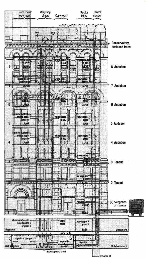
FIG. 7 Audubon House, New York City, renovated after its first 100 years,
now features four 20-in.-- (508-mm) --diameter steel chutes that conduct recyclables
to a subbasement resource-recovery center. Organic materials become compost
and are contributed to the roof garden. (Courtesy of the Croxton Collaborative
Architects, PC.)
(b) Audubon House
This New York City office building ( FIG. 7) utilizes several of the previously mentioned strategies and demonstrates some unusual design impacts of planning for recycling in offices. Built at the end of the nineteenth century, this eight-story building was reused rather than demolished when it was renovated (near the end of the twentieth century) to become offices for the National Audubon Society.
(The building has since changed tenants.) Many new materials made from recycled resources were installed; four new vertical chutes conduct recyclable materials to a subbasement resource-recovery center. Details about this project are available in Audubon/Croxton (1994).
The first stage of solid waste collection begins with two desktop recycled paper trays: one for paper for the employee's reuse, the other for recycling.
Two wastebaskets are provided per employee: one for mixed paper, the other for unrecycled garbage.
On each floor, central recycling points are gathered around four 20-in.-- (508-mm)--diameter steel chutes that run from top floor to subbasement. One of these chutes is for white (and computer) paper; the opening to this chute is in a vestibule for copy machines. The other three chute openings are in a "pantry" beside a small kitchen/break room and are for (1) organics (food wastes and soft soiled paper), (2) returnable plastic bottles and aluminum cans, and (3) mixed paper (colored paper, file folders, paperboard, sticky notes). In addition, shelves in each pantry accept returnable glass bottles, coated papers (juice and milk cartons), magazines, and newspapers.
In Audubon House's second stage of collection, custodians pick up the wastebaskets from the work areas and the collection from the pantry shelves.
These are taken to the subbasement recycling depot and sorted. In the third stage, large movable bins await deposits at the bottom of the four chutes.
Glass bottles, newspapers, and so on from the pan try shelves are collected and boxed or baled. Recyclable materials and garbage are periodically taken up to the delivery dock to recycling and garbage collectors. The exception is the organic waste. This compostable material is refrigerated until enough material accumulates. It is then screened (to remove the largest difficult-to-compost solids) and put into one of four composting "reactors," each with a 40 lb (18-kg) capacity. These are enclosed for odor control, yet are aerobic; air and heat, starter compost, and wood chips are provided to fast-start the pro cess at about 140ºF (60ºC). Each reactor is vented through filters to control odors. After about 3 days, the second compost stage begins, in which a steady flow of air sustains aerobic decomposition over a 3-month period. After this, the compost (greatly reduced in size and weight) has turned to humus and is taken to the roof garden.
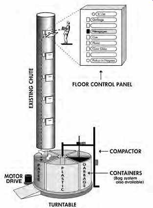
FIG. 8 One chute serves many different recyclables, as well as garbage, in
this Hi-Rise Recycling System. Interlocking access doors on each floor allow
only one user at a time; the user selects the type of recyclable being deposited,
using the control panel at the opening. (Courtesy of Hi-Rise Recycling Systems,
Inc., Miami, FL.)
5. EQUIPMENT FOR THE HANDLING OF SOLID WASTE
At Audubon House, four steel chutes of moderate diameter were inserted in the building's vertical core. Another approach is to use only one vertical chute, with a rotating receiving facility at the base ( FIG. 8). With up to six receiving bins on a carousel and a control panel at each floor opening, considerable floor space is saved compared to six individual chutes. (Also, custodial workers have fewer recyclables to separate and move.) The user first checks the control panel setting (it will be set at whatever bin the previous user had selected). After the user has made a selection, the carousel below turns to position the appropriate bin. The access panel then opens (interlocked so that only one floor can be opened at a time), and the recyclable material (or garbage) can be deposited. The receiving room at the base of the chute is about 12 ft (3.7 m) square, with a minimum height of 8 ft (2.4 m).
Where large amounts of solid waste are generated and little space is available in which to store it, various types of equipment can be used to change the volume or composition of the waste to facilitate its transportation and storage. The first step is to determine the probable daily flow of solid waste, as is done in Tables 1 and 2. When the extent of the problem is known, equipment can be selected.
(a) Compactors
Of the wide variety of compacting devices (FIG. 9), most are able to reduce the volume of solid waste to as little as 10% of the original volume.
Among the many choices to be made are vertical versus horizontal compaction, automatic chute fed versus manual free-standing, whether wastes are to be bagged or baled, and the final size of each unit of compacted waste. Compactors can be noisy; they can also be prone to fires as heat is generated in the compaction process. Many compactors have built-in sprays for both fire control and disinfecting.
Access to wash water and a floor drain are highly desirable.
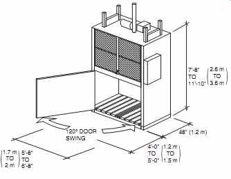
FIG. 9 A refuse baler/compactor may save storage space where particular waste
stream volumes are high. Cardboard, metal cans, and plastic bottles may be
more attractive to recyclable haulers when their volume is thus reduced. (Reprinted
by permission from AIA: Ramsey/Sleeper, Architectural Graphic Standards, 10th
ed. © 2000 by John Wiley & Sons.)
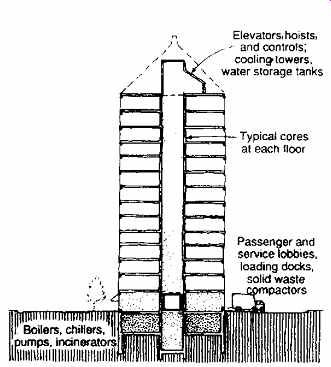
FIG. 10 Schematic section through a core of a multistory building. At the
top and bottom, floor space and ceiling height requirements increase. The consequences
on the ground (or delivery/collection) floor are particularly great.
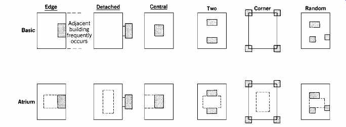
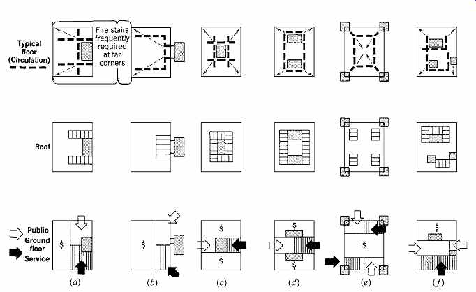
FIG. 11 Comparison of core arrangements and building plans. (a, b) The edge
and the detached cores give great flexibility to the rental floor area, with
light and view for core spaces. (c) The central core expands readily at the
roof and the ground floor, and has clear circulation and fairly flexible rental
space. (d) Two-core is a popular, workable arrangement. (e) The corner cores
give great flexibility to rental floors but are difficult at the roof and ground
floor. (f) Random cores generally occur in low-rise buildings, in which the
benefits of repetitious plans are minimal.
(b) Vacuum Systems
The primary advantage of a vacuum system is that it reduces the building volume consumed by waste chutes or storage cans on each floor. A grinder-plus evacuated-tube system is similar to the vacuum sew age systems described in Section 21.7. Vacuum conveying systems are now used in several industrial applications, such as ash and wood-chip transporting. Vacuum systems that use air, not water, as the transport medium are frequently used for linens in hotels and for trash. Separate vacuum systems for trash and linens are desirable, both to lessen the soiling of the linens and to allow them to be delivered to a destination different from that for the trash.
The advantage of such pressurized systems is that lines can be small, and the contents can be moved horizontally or even up. This allows far greater flexibility in design than is possible with gravity systems.
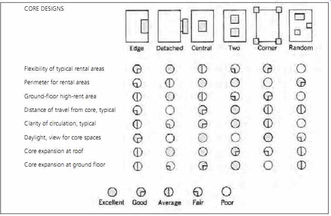
TABLE 4 Building Characteristics and Core Placement
(c) Summary
There are many options to be considered within the present waste-handling sequence of grind, crush, burn, and bury. As Earth's nonrenewable resources are stripped away, the recovery of materials from solid waste becomes increasingly attractive. The situation is similar to energy-and-design issues:
after decades of energy-intensive building trends, designers are now allocating space to daylighting atriums and allowing surfaces to act as thermal mass. A modest increase in floor space and equipment to encourage resource recovery from solid waste seems an increasingly worthwhile design investment.
6. THE SERVICE CORE
Medium- and high-rise buildings usually concentrate many building services within a core, from which services can be distributed as needed throughout each floor. The core typically contains stairs; passenger and freight elevators; toilet rooms; service closets; mechanical, plumbing, and electrical chases; electrical/telephone closets with local switching capabilities; fire protection equipment; and supply closets. The size of such cores varies widely; for example, the taller the building, the more elevators.
Often, these service cores are identical in plan from one floor to the next. Alternatively, the vertical services can be identical (stairs, elevators, chases) and the arrangement of other elements (toilet rooms, supply closets) allowed to vary. Whether or not minor floor-plan variations occur, the cores usually depart radically from the typical plan- and ceiling height-at both roof and ground floor ( FIG. 10). (Interruptions also occur where inter mediate mechanical floors are provided.) Depending upon the type of elevator machinery selected, the machine room ceiling height above the top floor being served might be three times the ordinary floor height. On the delivery/loading floor level, large trucks must be accommodated.
For chillers, boilers, incinerators, and fans, higher ceilings may be required to accommodate the flues, ducts, and pipes to which they must be connected; see Section 10.3 for the dimensions required. Considering the entrance lobby as an extension of the core, a building's service core can expand to nearly fill the ground floor. This core expansion typically happens on the roof and in the basement as well.
A service core can be related to the remaining service floor area in any of several ways ( FIG. 11). A single central core is probably the most familiar arrangement (Occidental Chemical Offices, Fig. 5.11; Fox Plaza Los Angeles, Fig. 10.10; International Building, San Francisco, Fig. 10.11; CBS Tower, Fig. 10.59). Frequent variations include a core at the edge ( Comstock Center, Fig. 10.63; Seeley Mudd Library, Fig. 10.65) or one that is detached, two cores symmetrically placed, corner cores, or core services dispersed somewhat randomly (Iowa Public Service Building, Fig. 10.41).
Each core location has advantages and draw backs. From the viewpoint of rentable space, important factors are the flexibility of the served (rental) floor area; the exposure of rental area to the perimeter, and thus to light, air, and view; and the extent to which ground-floor high-rent space gets commercial exposure. For fire safety and occupant convenience, the distance of travel from the farthest rental floor area to the service core and the clarity of circulation within the rental area, are important. For the environment within the core-toilet rooms, stairs, elevator waiting areas-access to light, air, and view is desirable.
For the mechanical services, ease of core area expansion on the roof, at the loading dock, and in the basement is important, as is the length of travel for ducts and other such elements within each floor. These factors are compared for various types of core designs in TABLE 4.
References and Resources
AIA: Ramsey/Sleeper. 1994. Architectural Graphic Standards, 9th ed. John Wiley & Sons. New York.
AIA: Ramsey/Sleeper. 2000. Architectural Graphic Standards, 10th ed. John Wiley & Sons. New York.
Audubon/Croxton. 1994. Audubon House: Building the Environmentally Responsible, Energy Efficient Office. John Wiley & Sons. New York.
Milne, M. 1976. Residential Water Conservation. U.S. Office of Water Research and Technology, Department of Commerce, NTIS. Springfield, VA.
Prev. | Next
Home Similar
articles top
of page