AMAZON multi-meters discounts AMAZON oscilloscope discounts
Among other issues, sections 20 and 21 considered the waste of resources inherent in the use of potable water to flush toilets. This section examines some consequences of this conventional approach to bodily waste removal, along with alternatives that use no water at all, and indeed that offer to convert waste to a useful resource. For typical U.S. residences, the potential impact of such alternatives on water usage and treatment is shown in FIG. 1.
Almost every plumbing fixture within buildings is provided with both water supply and waste pipes. Because the toilet is usually the largest user of water (FIG. 1), as well as one of the worst water polluters, this section begins with recycling/waterless alternatives to the flush toilet and urinals that were discussed in Section 21. Then more conventional systems using water to move waste, and conventional treatment systems from individual to large scale, are discussed. Discussions of graywater and storm water treatment complete this section.
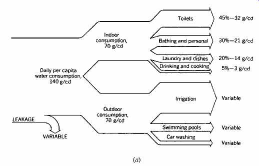
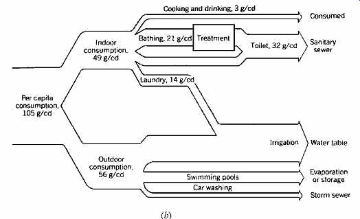
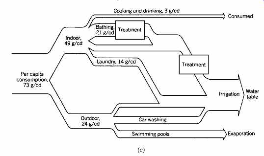
FIG. 1 Opportunities for water conservation for the typical U.S. family.
(a) At present, the average U.S. residential usage is about 140 g/cd (gallons
per capita per day) [530 L/cd; liters per capita per day]-all of it potable.
(b) With attention to recycling and the matching of water quality to usage,
potable water usage could be cut to 105 g/cd (397 L/cd)-a 25% reduction. (c)
With further on-site treatment and recycling, potable water usage drops to
73 g/cd (276 L/cd)-a 40% reduction-and the need for public sewage treatment
(for residences) disappears. (From Milne, 1976.)
1. WATERLESS TOILETS AND URINALS
The array of waterless alternatives includes toilets in which chemicals or oil are substituted for water.
These devices are commonly found in airplanes, vehicles, and boats, as well as in remote and environmentally sensitive areas. The chemicals must be frequently recharged and the waste products removed. Other waterless toilets temporarily treat the waste awaiting discharge to a sewer by freezing it, burning it, or otherwise packaging it so that it remains inoffensive. Such devices can become energy-intensive approaches to waterless waste disposal. Also, they are still dependent upon public sewer systems.
(a) Composting Toilets
Once considered too unconventional to ever gain mainstream acceptance, these ecologically attractive devices are now appearing not only in homes but within institutional buildings (FIG. 2). Per haps several generations needed to pass between regular use of the historic outhouse and use of these modern composting toilets. They offer a self contained and low-energy strategy for providing waterless toilets. Wherever water supplies are unreliable, or waste discharge is difficult or prohibited, composting toilets offer an alternative. Silent and immune from potential water damage (freezing pipes or overflows), these systems rely upon aerobic digestion of waste (i.e., that which occurs in the presence of oxygen). Aerobic systems usually are essentially odor-free, and the exhaust air is rich in CO2 (not necessarily good) and water vapor (harmless). In contrast, anaerobic decomposition (i.e., that which occurs without oxygen) is malodorous and produces methane gas as a key by-product. See Sections 7 and 8 for more about methane and anaerobic decomposition.
Waste material deposited in composting toilets builds up in a mound, which retards the flow of air for decomposition. Wood shavings are commonly added with each use to encourage toppling of the mound and to add some carbon to the resulting compost. Some composting toilets include a means of regular mechanical stirring of the compost chamber, aiding aerobic decomposition.
Ventilation is important, both to reduce odors and to facilitate evaporation of excess moisture. A ventilation stack is an essential feature; it is often assisted by a very small (3- to 5-W) fan. Problems with insects hatching within the composting chamber can be lessened by keeping vegetable scraps out of the chamber, as they are frequent sources of insect eggs.
The C.K. Choi Building at the University of British Columbia (FIG. 2) eliminated a connection to the city sewer system by a combination of composting toilets and a graywater treatment system. The composting toilets in this three-story, 30,000-ft 2 (2787-m2) facility for the Institute of Asian Research are estimated to save 1500 gal (5680 L) of water per day. At an estimated 30,000 uses per year, these composting toilets are expected to produce an annual compost yield of about 4 ft 3 (0.1 m3). In addition, their liquid end product will be added to the graywater treatment system at the rate of about 3 to 5 gal (11 to 19 L) per day. The composting chambers are located in a small basement below the toilet rooms at the center of the building.
The graywater includes waste from lavatories and sinks, as well as liquid from the composting toilets. This water drains into the subsurface "graywater trench," containing a variety of phragmite plant material. The roots support microbial life known for digesting and neutralizing bacteria. This graywater is then used for irrigation. Graywater systems are discussed further in Section 9.
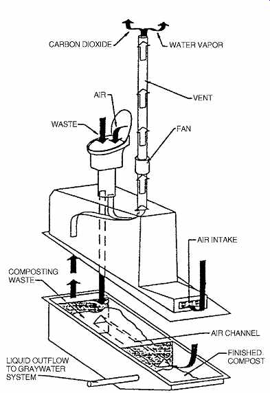
FIG. 2 Composting toilets save water and eliminate a sewer connection.
They are used at the C.K. Choi Building, University of British Columbia, Canada,
where the toilet rooms are concentrated near the center stairs, with a small
basement below containing composting chambers and a rainwater cistern for irrigation.
The composting toilets produce both dry humus and a liquid outflow to a graywater
recycling system. (Courtesy of Matsuzaki Wright, architects, Vancouver, BC.)
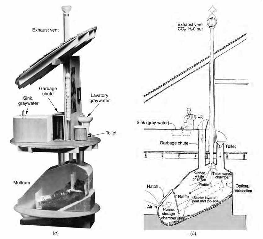
FIG. 3 Clivus Multrum System, with composting of both kitchen and toilet
organic wastes. (a) The lower composting chamber requires 4 × 8 × 7 ft (1.2
× 2.4 × 2.1 m) of floor space, a generous supply of air (warm air speeds decomposition),
and access for periodic removal of the garden-ready humus. (b) It must be arranged
so that its upper end receives toilet wastes; as the bottom slopes downward,
kitchen wastes are deposited on top of the decomposing toilet wastes. The vent
stack ensures continuous airflow, pre venting odors from entering bathroom
or kitchen. The toilet seat and cover must be kept closed when not in use to
keep air flowing through the composting chamber and out of the stack. The toilet
bowl (containing no water) swings open when the seat is occupied, exposing
the composting chamber below. (Courtesy of Clivus Multrum USA, Inc.)
(b) Vault-Type Composting Toilets
The Clivus Multrum system (FIG. 3) has a large decomposition chamber that must be below the toilet (and perhaps also the kitchen), from which it readily accepts organic waste. It must also be accessible to remove the humus-varying between 3 to 10 gal (11 to 38 L) of soil per person per year.
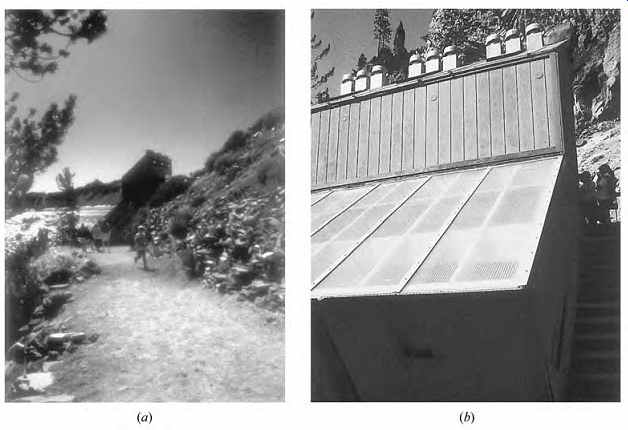
FIG. 4 On the shore of Crater Lake, Oregon, (a) a building with three Phoenix
composting toilets serves visitors. An attached sun space (b) contains and
warms the composting chambers and contains an evaporator for liquid waste.
The facility is closed all winter.
The relatively large chamber (about the size of a Volkswagen "bug") and its low position/access requirement can have a significant impact on design. Also of significance is the device's appetite for fresh air. The more air it has, the speedier the process of aerobic decomposition and, therefore, the less odor. In winter, this airflow could cause increased heat losses by infiltration in a building.
The natural ventilation due to the stack effect is at least 15 cfm (7 L/s) in the Clivus Multrum. A ventilating fan in the stack will increase this rate significantly. However, if outdoor air is brought directly to the chamber, it could be too cold for proper decomposition; a chamber temperature of 98ºF (37ºC) is optimum. Solar heating of input air offers one alternative. However, adding too much heat to compost piles encourages oxidation rather than aerobic decomposition; inferior compost results.
Another composting toilet application is shown on the shores of Oregon's Crater Lake National Park in FIG. 4. Consider the challenge: this facility is at the bottom of a 1-mile trail down from the crater rim; public sewers are miles away and hundreds of feet higher in elevation; severely cold winters and deep snow close the trail for more than half of the year; and Crater Lake is one of the clearest in the world, so water pollution is absolutely to be avoided. Three Phoenix composting toilet tanks sit within a solar-heated attached sunspace.
The Phoenix composting tanks (FIG. 5) feature rotatable tines that speed aerobic decomposition. They also can be fitted with an evaporation system, typically using a small photovoltaic (PV)-driven pump that delivers liquid to the top of a drip tank filled with plastic balls. This presents a very large surface area, and a small fan also aids evaporation.
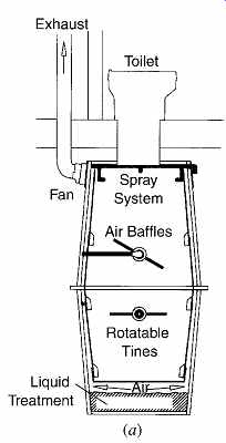
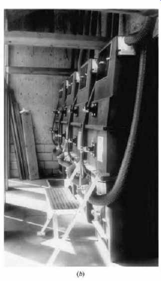
FIG. 5 The Phoenix composting toilet's tank serves either two toilets or
one toilet and one food waste inlet. (a) Schematic section; rotatable tines
mix waste and control the movement of compost to the access area for eventual
removal. The fan exhausts air from the Phoenix tank to control odors. Passing
behind the air baffles, air makes frequent contact with the compost pile, ensuring
aerobic decomposition. After passing through the compost pile and receiving
secondary treatment in the bottom of the Phoenix, liquid is periodically sprayed
on top of the compost pile to keep the pile moist and inoculate fresh waste
with decomposing organisms. Each tank is 39 in. (1000 mm) wide and 61 in. (1550
mm) long, and requires another 5 ft (1525 mm) in front for maintenance access,
and is avail able in three heights: 55 in. (1400 mm), 73 in. (1850 mm), and
92 in. (2350 mm). Another 12 in. (300 mm) above the top of the tank is convenient
for maintenance. (b) Four chambers with their rotatable tines serve the Vogelsang
High Sierra Camp at Yosemite National Park, California. (Courtesy of Advanced
Composting Systems, Whitefish, MT.)
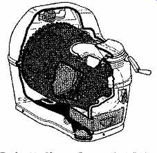
FIG. 6 The Sun-Mar "Compact" composting toilet has a "Bio
drum" that is turned by a hand crank. The crank folds back into the body
of the toilet after use. It also uses a 200-W electric heater to speed decomposition,
a 25-W fan, and a 2-in. (50-mm) vent that attaches at the rear. The self-contained
unit is designed for light residential use. (Courtesy of Sun-Mar Corporation,
Tonawanda, NY.)
(c) Heater-Type Composting Toilets
Another approach puts the composting chamber within the toilet itself. The more compact the composting chamber, the more likely that heat must be added to speed decomposition and to evaporate liquid. Although electricity provides an easy and com pact way to heat, using such high-quality energy to treat waste reduces the compact toilet's ecological advantage.
In the most compact of Sun-Mar's products (FIG. 6), a variable-diameter Bio-drum is turned by a fold-out hand crank at the front of a rather conventional-looking toilet. At this size, it is rated for continuous residential use by one adult or a family of two (or for weekend/vacation use, by three adults or a family of four). Sun-Mar uses a three-chamber approach, separating the quick composting of waste and toilet paper, the evaporation of liquid, and the safe storage of the finished compost.
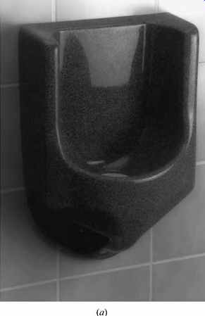
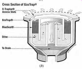
FIG. 7 Using no water, (a) the Waterless No-Flush urinal employs a special
liquid to allow urine to pass through (b) while keeping sewer gas trapped in
the waste pipe. (Courtesy of the Waterless Company LLC, Del Mar, CA.)
(d) Waterless Urinals
Urine is often kept out of composting toilets for several reasons. First, excess liquid in the chamber creates a discharge issue, complicating an otherwise simple end result of occasional harvesting of garden ready humus. Second, urine is nearly sterile and an excellent fertilizer, and its separate capture could be useful. If not captured, urine can be directed either to a graywater or to a wastewater system.
Waterless No-Flush urinals utilize a floating layer of BlueSeal liquid that forms a barrier to sewer vapors but allows urine to readily pass through (FIG. 7). This liquid does not dissolve, mix, or react chemically with urine. It is more than 95% biodegradable and does not evaporate at 100ºF (38ºC). Because 1 quart (0.9 L) of this liquid lasts for 15,000 to 20,000 urinal uses, it replaces an estimated 15,000 to 60,000 gal (56,780 to 227,120 L) of water that would have been used by conventional flush urinals. The trap retains sediments and should be emptied occasionally, and the liquid is periodically replenished (3 oz [89 mL] per 1500 uses).
2. PRINCIPLES OF DRAINAGE
Early in the history of indoor plumbing, waste drainage was a simple matter; a pipe containing wastewater led to a sewer (FIG. 8a). Before long, the noxious gases that were created by the anaerobic conditions in sewers became a threat to the health of those indoors. Thus, the trap was invented (FIG. 8b) to block the pipe so that gases could not pass. However, as moving water fills the pipe downstream from a trap, the mass of water acts as a plunger, creating higher pressures in front and negative pressures behind. The positive pressures might force sewer gas through the water in other traps; worse, the negative pressures could suck (or siphon) the water from the trap, leaving it open to gas pas sage. The installation of vents provides a way to deal with these pressures so that the suction draws air down through the vents rather than water from the traps (FIG. 8c). A typical arrangement of fixtures, traps, and vents is shown in FIG. 9.
(a) Traps
The only separation between the unpleasant and dangerously unhealthy gases in sanitary drain age pipes and the air breathed by room occupants is the water caught in the fixture trap after each discharge from a fixture. Sufficient water must flow, especially in water closets, to keep this residual water clean. Traps are made of steel, cast iron, copper, plastic, or brass-except those in water closets and urinals, which are often made of vitreous china cast integrally with the fixture. The deeper the seal, the more resistance to siphonage but the greater the fouling area; therefore, a minimum depth of 2 in. (50 mm) and a maximum depth of 4 in. (100 mm) are common standards. All traps should be self-cleaning, that is, capable of being completely flushed each time the trap operates so that no sediment will remain inside to decompose.
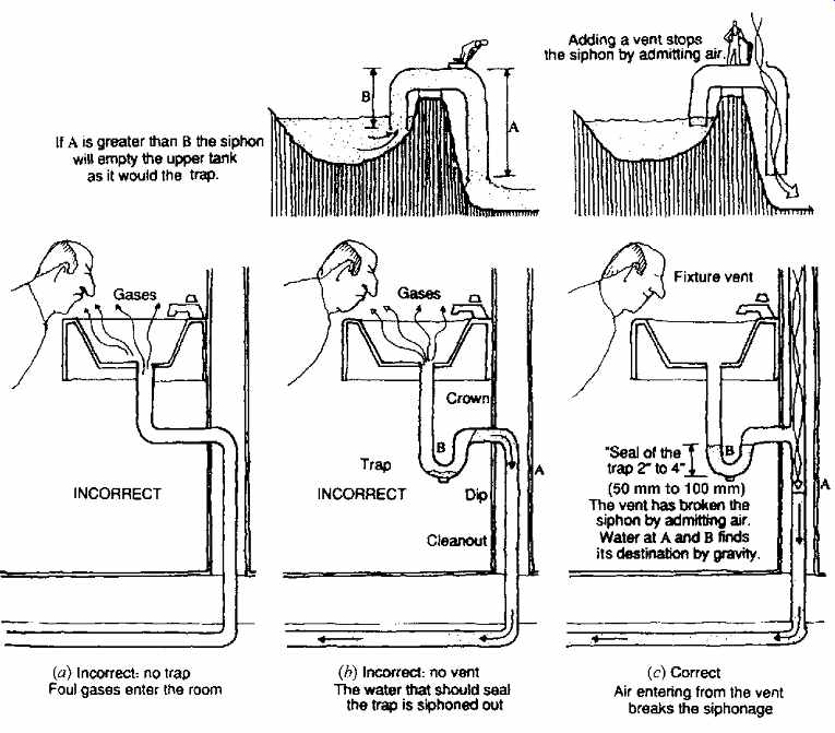
FIG. 8 Function of a trap and one of the several functions of a vent (preventing
siphonage).
There are a few exceptions to the rule that each fixture should have its own trap. Common exceptions include two laundry trays and a kitchen sink connected to a single trap; not more than three laundry trays using one trap; and three lavatories on a single trap. In the case of the laundry trays and sink, the sink is equipped with the trap and set closest to the stack (see stack b in FIG. 9).
Traps are usually placed within 2 ft (610 mm) of the fixture and should be accessible for cleaning through a bottom opening that is otherwise closed by a plug. Overflow pipes from fixtures are connected to the inlet side of the trap. In long runs of horizontal pipe, so-called running traps are used only near drains in floors, areaways, or yards and should be provided with hand-hole cleanouts. " Island" sinks pose a special problem when the vent line cannot lead up from such a location. The sink's waste line can be taken to a distant sump, which is then itself trapped and vented.
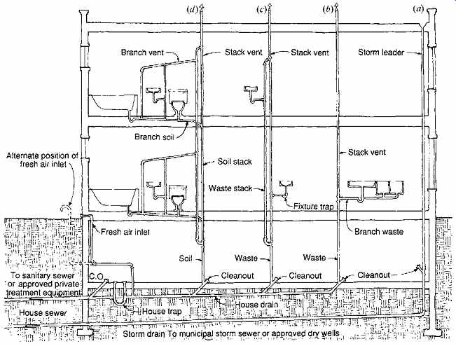
FIG. 9 Typical sanitary drainage system, which separates storm water from
sewage. This installation combines blackwater (from water closets) and graywater,
although their separation would encourage graywater recycling. The house trap
is optional under some plumbing codes and illegal under others (because sanitary
sewers could be vented at street level through the fresh air inlet).
When fixtures are used very infrequently, the water in traps can evaporate into the air, breaking the seal of the trap. In contemplating the possible frequency of use, this fact should be kept in mind by the designer. Unoccupied residences (such as weekend or vacation homes) may experience sewer gas penetration through traps emptied by evaporation. Otherwise, evaporation to a dangerous degree rarely occurs, except in the case of floor drains. Used to carry away the water used in washing floors or drained from heating/cooling equipment, floor drains may often lose their water seal between their infrequent uses. Some authorities are reluctant to approve floor drains connected to a building sewer, requiring instead that they be separately connected to a dry well. In either case, the use of a special hose bibb, affording a source of water directly above the drain, is a wise precaution. It can easily be used to manually refill the trap of the drain. Other strategies include using a deep trap drain and/or providing a drip source of water to maintain the trap seal.
(b) Vents
To admit air and discharge gases, soil and waste stacks are extended through roofs, and a system of air vents, largely paralleling the drainage system, is provided. As in the case of drainage stacks, the ventilating stacks extend through the roof or vent through the drainage stack. The functions of venting are often misunderstood. It is true that one important purpose is to ventilate the system by allowing air from the fresh-air inlet (or from the sewer, if there is no house trap or fresh-air inlet) to rise through the system and carry away offensive gases. This provides some purification for the piping. However, several other purposes are served by the vent piping. The introduction of air near a fixture (and, in the case of circuit vents, at the branch soil line) breaks the possible siphonage of water out of a trap. Under other circumstances- namely, when drainage fluids descend to a fixture group through the soil stack-the foul gases, under pressure, could bubble through the trap seals of that group. The vent system provides a local escape for these gases. Circuit venting-which permits air and gases to pass in and out of the soil or waste branch instead of at each fixture, as in the case of continuous venting (individual fixture venting)-can pre vent the siphonage of trap seals or their penetration by gases (FIG. 10). Some codes may prohibit circuit venting.
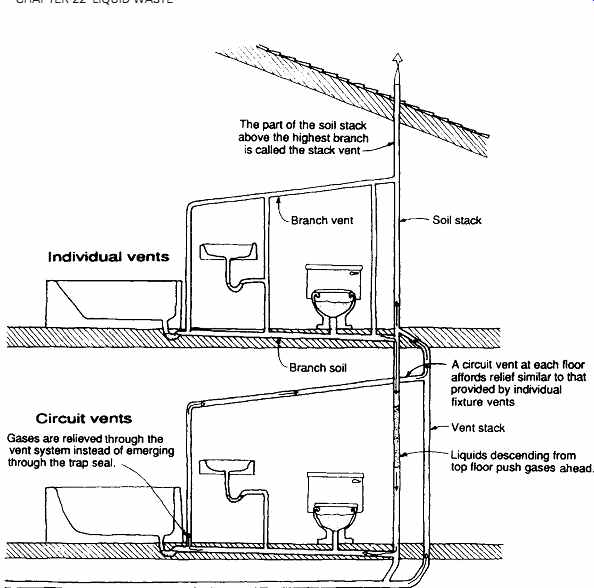
FIG. 10 Sewer gas relief through vents. Gases pressurized by hydraulic
action or by expansion due to putrefaction have an escape path through the
vent system and will not enter the rooms. The upper floor shows individual
vents (a vent at each fixture); the lower floor shows circuit vents, permitted
by some codes, where one vent serves the entire branch.
(c) Air Gaps and Vacuum Breakers
Nearly every plumbing fixture is supplied with pure water at one point, and most discharge contaminated fluids at another. The proximity of sewage to potable water at most fixtures is inescapable; sewage could accidentally be siphoned into a pipe carrying potable water. Consider an improperly placed faucet whose outlet is below the rim of a fixture. If the fixture overflow is plugged and the fixture bowl full, the faucet can easily project into the foul drain age water. If, in this circumstance, the water piping is drained while the faucet is open, contaminated water could be drawn by suction into the water piping.
In water closets served by flushometers (flush valves), the water supply unavoidably enters the bowl below the rim. A vacuum breaker placed in the flushometer closes with water pressure but opens to admit air if there is suction in the water pipe. This prevents siphonage in much the same way that a vent prevents trap siphonage (FIG. 11). The use of vacuum breakers at dishwashers and clothes washers was diagrammed here. These are especially important locations because, in both of these appliances, pumps force wastewater into a drain line.
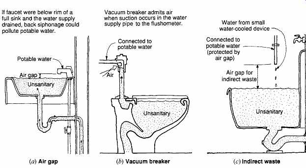
FIG. 11 Backflow preventers. Unsanitary fluid wastes cannot be siphoned
into the potable water piping in these three examples.
3. PIPING, FITTINGS, AND ACCESSORIES
(a) Piping and Fittings
The materials used within buildings for soil and waste piping and for venting include cast iron, copper, acrylonitrile butadiene styrene (ABS) plastic, and polyvinyl chloride (PVC) type drain age, waste, and vent (DWV) pipe (Table 1, FIG. 12). Galvanized steel is sometimes chosen for vents and for tall stacks in high-rise structures. Sometimes, different materials are used in the same system. Where dissimilar metals are connected, dielectric unions are used to pre vent corrosion due to electrolysis. Materials used underground for sewage disposal (depending upon local codes) include vitrified clay tile, cast iron, copper, asbestos-cement, ABS plastic, PVC type DWV, and concrete pipe.
Cast Iron. Used first in Germany around 1562 and appearing in the United States about 1813, cast iron supplanted the tubing and culverts of earlier eras that employed clay, lead, bronze, and wood. Cast iron was thus the earliest of the modern materials used for piping. Its durability and resistance to corrosion make it appropriate for a wide range of uses, from small residential work to the stacks and branches of tall buildings.
(coming soon) TABLE 1 Materials for Waste Piping Typical fittings for sanitary drainage appear in Figs. 12 and 13. (table coming soon)
In sanitary flow systems composed of any material, changes in direction must be made with easy bends. To prevent clogging or fouling by the solid materials flowing in the piping, right-angle connections are not used. Thus, for sanitary drainage systems the available options in FIG. 13 would be the one-eighth bend connected to a 45º Y, or the one-quarter bend long sweep. The 90º T, in the position shown, would be used only in a vent system.
The three cast-iron soil pipe joints shown in FIG. 14 represent semirigid, watertight, and gas tight connections of two or more pieces of pipe or fittings in a sanitary system. Types b and c provide a quieter plumbing system and slightly more flexible joints than type a. See FIG. 15 for cast-iron soil pipe and fittings in bathroom groups.
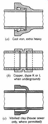
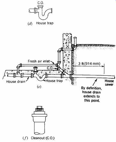
FIG. 12 Piping and fittings. (a) Connection of cast iron piping. (b) Coupling
to connect copper tubing. (c) Connection of vitrified clay piping. (d) Detail
of house trap fitting. (e) House drain, house trap with cleanouts and vent
(fresh air inlet), and house sewer. (f) Clean out showing removable threaded
plug. For large buildings, the terms building drain, building sewer, and so
on supplant house. Local codes differ on inclusion or omission of the house
trap. Note: plastic pipe connections are similar to that in (b).
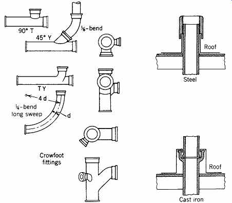
FIG. 13 Principal types of cast-iron fittings and method of flashing at
roofs for steel and cast iron.
Copper Tube and Fittings for DWV. There are several tube classifications for the copper products used in plumbing systems: types K, L, and M are for water supply systems, and type DWV is for drainage, waste, and vent installations. Connections between copper tubing and its couplings or fittings involve a sliding fit between components (see FIG. 12b). Bridging the mating surfaces is a cylindrical capillary space filled with solder.
The process of making the joint is a simple one, utilizing a flux, heat, and solder. Properly made, the joint will be airtight and capable of with standing high pressure (although such pressure is not normal in waste lines). To undo the joint for repair or renovation, one simply reheats it until the solder melts. Like cast iron, copper has a history of use in ancient installations. Updated and highly developed in recent decades, it is now in widespread use.
Plastic Materials for DWV. Along with copper and cast iron, plastics are suitable for sanitary drainage systems. Table 1 lists the plastics suitable for drainage, waste, and vent, as well as for building drains and sewers. Acrylonitrile butadiene styrene (ABS) is identified and further described by the labeling shown in FIG. 16. One of several steps used in making a "solvent-weld" connection is seen in FIG. 16, as is a method of support used in wood frame construction. Figure 17 shows assembled bathroom piping in place. One advantage of plastic piping is its relatively light weight, allowing some preassembly in a location with conditions better than might be available at the final installation location, with the assembly then being carried to its place of installation.
(b) Accessories
Among the many special devices that can form part of a plumbing system are floor drains, backwater valves, ejectors, and interceptors.
Floor Drains. When floors in buildings must be washed down after operations such as food preparation and cooking, floor drains are usually necessary. Figure 18 shows a typical floor drain.
Because these drains are often connected to sanitary drainage systems (rather than dry wells) and, in long periods of disuse, might lose their trap seals by evaporation, special precautions are necessary to preserve the trap seal and avoid odors and unsanitary conditions in the room.
Backwater Valves. These devices (FIG. 19) are sometimes used when plumbing fixtures are installed at low elevations, such as in basements, or in other locations that are near the level of the sewer.
They cannot be used to protect the entire plumbing system and should be used only when necessary.
They must be accessible for maintenance. An alter native to the use of backwater valves is the sewage sump.
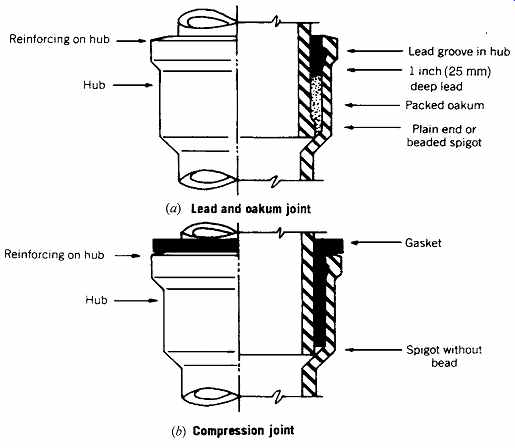

FIG. 14 Various joints used to connect cast-iron soil pipe and fittings.
(Courtesy of the Cast Iron Soil Pipe Institute.)
Sewage Sumps and Ejectors. Whenever subsoil drainage, fixtures, or other equipment are situated below the level of public sewers, a sump pit or receptacle must be installed. The drainage from the low fixtures may flow into this pit by gravity, and from it the contents are then lifted (ejected) up into the building sewer.
Sewer ejectors may be motor-driven centrifugal pumps (FIG. 20), or they may be operated by compressed air. The latter have no revolving parts within the receptacle. An air compressor is started when a float within the sump reaches a certain level, and air at a pressure greater than 0.433 psi for each foot (10 kPa for each meter) of lift is delivered into the space above the liquid.
The air pressure closes the inlet and opens the outlet check valves, expelling the contents of the sump and elevating it to the sewer.
Interceptors. Sanitary drainage installations ultimately discharge their waste matter into private or public sewage treatment plants that attempt to digest or cope with anything that may come through the pipes. Because it is impossible to control what will be discarded into the plumbing drains, trouble can occasionally be expected. The problem can be reduced somewhat by devices known as interceptors, which catch foreign matter before it travels too far into the system.
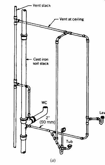
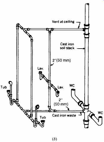
FIG. 15 Two typical piping arrangements for a water closet, lavatory, and
tub. (a) For a multistory installation with each fixture vented; (b) for a
single-story, back-to-back installation. (Courtesy of the Cast Iron Soil Pipe
Institute.)
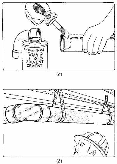
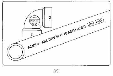
FIG. 16 Details of the use of plastic pipe. (a) One of the steps in making
a solvent weld of a plastic pipe to a plastic fitting. (b) In wood frame construction,
plastic pipe assemblies can be sup ported by metal straps nailed to wood joists.
The supports should be more closely spaced than those for metal piping because
of plastic's increased flexibility. (c) Typical identification symbols on plastic
pipe: ACME-the name of the manufacturer; 4 in.-diameter of the pipe; ABS-acrylonitrile
butadiene styrene, the material; DWV-suitable for drainage, waste, and vent;
SCH 40- Schedule 40, this identifies the wall thickness of the pipe; ASTM D2661-the
applicable American Society for Testing and Materials standard; NSF DWV-tested
by the National Sanitation Foundation Testing Laboratory, the pipe meets or
exceeds the current standards for sanitary service. (Courtesy of the Plastic
Pipe Institute.)
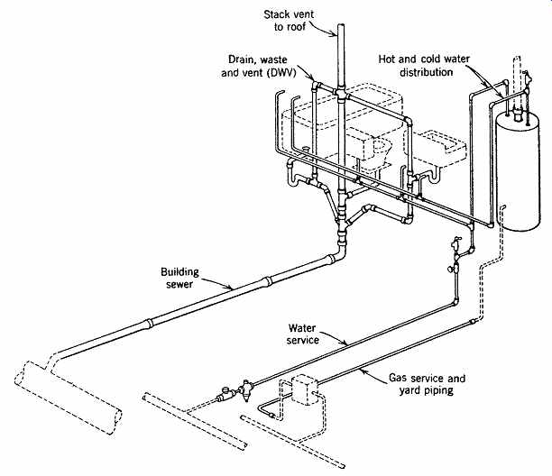
FIG. 17 Plastic piping (solid lines) for water service, gas service, hot
and cold water supply, and for drainage, waste, and vent. Gas service below
grade can be PE, PB, or PVC. (Courtesy of the Plastic Pipe Institute.)
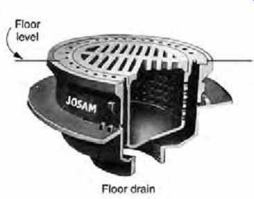
FIG. 18 Floor drain. (Courtesy of the Josam Manufacturing Company.)
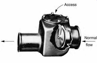
FIG. 19 Backwater valve, with access to facilitate unclogging and cleaning.
FIG. 20 Sump (a) and ejector pump (b). A submersible-type centrifugal pump for raising sewage to a higher level. Shown here for an outdoor subgrade sump installation, it may be used in basement applications within buildings. Venting must be carried to the roof. (Courtesy of the Weil Pump Company.)
Interceptors require periodic servicing. Interceptors for as many as 25 different kinds of extraneous material are listed by manufacturers. They include devices to catch hair, grease, plaster, lubricating oil, glass grindings, or material from many industrial processes. One of the few interceptors that is sometimes used in homes, but more often in institutional kitchens, is the grease interceptor, or grease trap. As the waste is passed from a kitchen sink through the circuitous path within the grease interceptor, the grease floats to the top, where it is trapped between baffles, while the more fluid wastes pass through at a lower level (FIG. 21). If not so intercepted, grease congeals within piping and thus physically retards the sewage collection process.
Cleanouts. Clogging of sanitary drainage piping systems is very possible-if not likely. From all plumbing fixtures to the end of the disposal process, all parts of a sanitary piping system should be accessible through cleanouts (FIG. 12) and/or other points of access to relieve clogging that will often occur in the piping (as well as in the septic tank or public disposal plant).
4. DESIGN OF RESIDENTIAL WASTE PIPING
In residential work, the piping assemblies may often look like a "flag," where the mast is the soil stack, the horizontal top of the flag is the branch vent, the bottom is the soil or waste branch, and the outer edge is the vertical pipe of the last fixture. In wood or steel frame construction, the flag usually fits into a 6-in. (150 mm) partition. Fixture branches project from the surface of the flag. There is considerable advantage in back-to-back layouts for baths and kitchens; this allows the piping assembly to pick up the drainage from fixtures on both sides of the piping. When all the fixtures are on nearly the same level, it is unnecessary to have a separate vent stack next to the soil stack, as is often the case in multistory construction. Generally in one-story construction, the upper part of the soil stack is extended to form a vent called a stack vent, to which the branch vents connect.
A separate major vertical vent is called a vent stack.
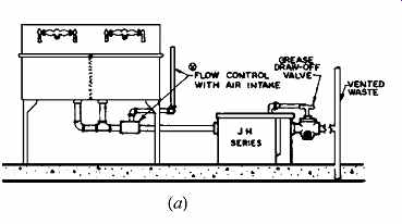
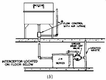
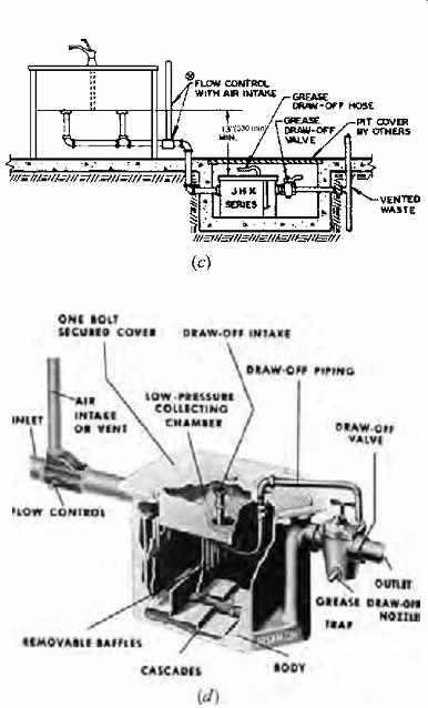
FIG. 21 One type of institutional interceptor, a grease trap. Choice of
three locations-adjacent to the sink (a), on the floor below (b), or in a pit
(c). Periodic cleaning is both necessary and unpleasant; easy access is helpful.
(d) Cutaway view with identification of component parts. (Courtesy of the Josam
Manufacturing Company.)
The task of fitting two generally parallel plumbing "distribution trees" (supply and waste) into available horizontal and vertical chases can be difficult. This is especially true of the waste system, which has larger pipes, because it is not under pressure and must carry solids as well as liquids.
To compound the problem, because of gravity flow requirements, these larger pipes must slope continuously downward, from fixtures to the sewer.
In residences, the best available "vertical chase" is sometimes nothing more than an extra-thick wall, increasing the difficulty of coordination.
In residential applications (and other relatively small buildings), certain fairly standard minimum sizes (such as a 4-in. [102-mm] soil stack and building drain) are usually adequate.
Horizontal fixture branches from individual fixtures should be the same size as the fixture trap.
Horizontal fixture branches from groups of fixtures are sized by the drainage fixture units of the group. For individual fixture vents, the vent size is usually the same as the size of the fixture's horizontal branch. Under many codes, vertical vents that penetrate the roof must increase to a 4-in. (102-mm) size to prevent blocking by icing in freezing weather.
Tables 2 through 5 list minimum pipe sizes to carry waste and serve for venting.
EXAMPLE 1
Design, layout, and size the piping for the sanitary drainage system for the house shown.
(coming soon) TABLE 2 Drainage Fixture Units (dfu)
(coming soon) TABLE 3 Horizontal Fixture Branches and Stacks
SOLUTION
The first step is to identify the locations where hot and cold water is needed at fixtures and where soil or waste drains must be provided. Figure 23a illustrates how this is done. A plan layout for the drains in both levels follows (FIG. 23b).
Next comes the plumbing section (FIG. 24). The local administrative authority usually requires this to be submitted for approval. Pipe sizes are determined from Tables 2 through 5. Drain age fixture units (dfu) for this system are summarized in Table 6 from data given in Table 2.
Although Table 3 permits a 3-in. (76-mm) branch for up to 20 dfu, it is common practice to use a 4-in. (102-mm) branch for every water closet (or every group of water closets totaling 20 dfu or less). Because Table 3 allows 160 dfu for a 4-in. (102-mm) branch, this size is acceptable for any branch to which a water closet is connected.
This size is also more than adequate for the stack in this example.
A water closet must have a 2-in. (51-mm) vent. Table 4 shows that a 2-in. (51-mm) vent, for developed vent lengths not exceeding 150 ft (45.7 m), will serve 20 dfu. This size is acceptable for all branch vents in this example.
The house drain should not be less than 4 in. (102 mm). From Table 5, at a ¼-in. fall per foot (2.1% slope), a 4-in. (102-mm) house drain will carry 216 dfu, which is more than adequate for our 26-dfu system.
There are prefabricated bathrooms in which a manufacturer assembles the piping for preselected fixtures (FIG. 25). Going further, there are a few examples of entirely one-piece bathrooms, which incorporate the maintenance advantage of having no seams between fixtures, walls, and floors. This, of course, makes fixture replacement expensive and difficult, and tends to put the burden of access to plumbing on adjacent rooms.
For the more ordinary bathroom, the two maintenance questions of greatest concern are (1) how easy is cleaning around and within the fixture, and (2) how accessible are those parts of the fixture most likely to need repair or replacement? Ease of cleaning is often determined more by the space around the fixture than by the design of the fixture itself.
This is particularly true of toilets, where a generous amount of open floor on either side makes maintenance easy and therefore likely to be more frequent.
Access to fixture parts may be more difficult. An access panel in the wall of the room behind the fixtures is often provided, encouraging speedy repair and replacement for components at tubs, showers, and lavatories. Ideally, accessibility to all plumbing lines--whether via access panels in walls, trenches in concrete floors, exposed basement ceilings, or adequately deep crawl spaces-should be provided.
Most bathrooms are likely to undergo thorough remodeling, including fixture replacement, as styles change and water/energy conservation becomes more important.
5. DESIGN OF LARGER-BUILDING WASTE PIPING
(coming soon) TABLE 4 Size and Developed Length of Stack Vents and Vent Stacks
(coming soon) TABLE 5 Building Drains and Sewers
(coming soon) TABLE 6 Drainage Fixture Units (dfu) for Example 1a
(a) Basic Planning
Multistory construction, especially in office buildings, is often designed to be flexible and free of random partitions that would interfere with the periodic renovation of interior spaces and the relocating of dividing partitions. Building "cores" contain elevators, stairs, and shafts for plumbing, mechanical, and electrical equipment. Cores are often placed in the central section of the building, freeing the surrounding areas for access to daylight. A hole in the floor for each pipe is often chosen in preference to a slot or shaft. This method usually interferes less with the floor construction (FIG. 26).
Offices often need a single lavatory or a complete toilet room for executives at locations away from the central core of the building. The greater the horizontal distance from the core, the more vertical clearance that will be needed to allow the drain to slope. When such vertical clearance becomes difficult, "wet" columns with a full complement of plumbing pipes offer a solution. If the pipes are to accompany a column in a steel building, structural coordination must be sought early in the planning if the pipes are to clear the structural framing of the floor (FIG. 27).
In some installations, the branch soil and waste piping perforates a floor and crosses below the slab to join the stack. Tubing has been developed, however, that sits above the structural slab, obviating the need for hung ceilings below (FIG. 28). A lightweight concrete fill is cast to cover the tubing, raising the floor by 5 or 6 in. (125 or 150 mm). This can create a raised floor in the toilet room-with associated access problems-so the higher floor level is usually carried throughout the entire story, forming a convenient space into which the electrical conduit can be placed at a time later than would have been required if it were to be placed in the structural slab. Such raised floors are becoming more common, along with the HVAC strategy of underfloor air distribution.
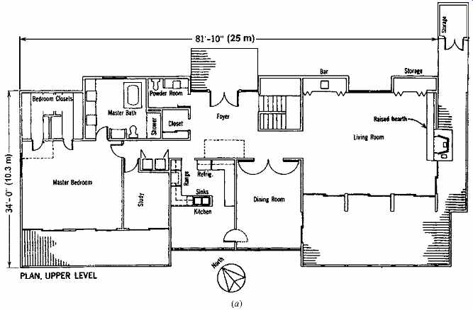
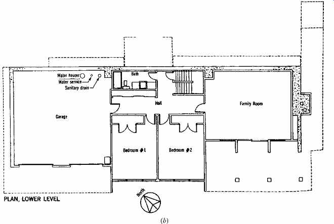
FIG. 22 Example 1. Floor plans of a house on Long Island, New York.
(Budd Mogensen, architect and planner.)
FIG. 23 Example 1. (a) Plumbing requirements, water supply, and partial
sanitary drainage. (b) Sanitary drainage plan.
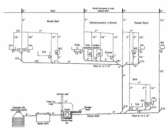
FIG. 24 Example 1. Plumbing section. When every fixture is vented individually,
as in this example, the method is known as continuous venting. In larger systems,
batteries of fixtures may be vented by a loop or circuit vent. This reduces
the amount of piping in the vent system (see FIG. 10 and FIG. 30). Note
that septic tank discharge to a leaching pit is not permitted in many locations;
see Section 6.
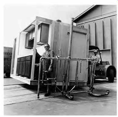
FIG. 25 Preassembled plumbing tree for manufactured housing, along with
the prefabricated kitchen/bath in which it is installed. (Courtesy of Wausau
Homes, Inc., and the Copper Development Association.)
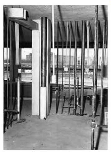
FIG. 26 Plumbing risers in a fireproof multistory building.
Pipes, tubes, conduits, and ducts adjoin toilet rooms and utility spaces. Ventilation ducts and a master 5-in. (127-mm) copper hot-water riser are just to the left of center. Soil and vent stacks with hot and cold water supplies, all of copper, are to the right of this group. At the left, in a lighter tone, are the galvanized steel feeder conduit and distribution circuit conduits for a local electrical control panel box. Note that some pipes and tubes are supported at this floor by bolted clamps. After testing and before pipes are enclosed, covering will be completed. (Courtesy of Copper Development Association.)
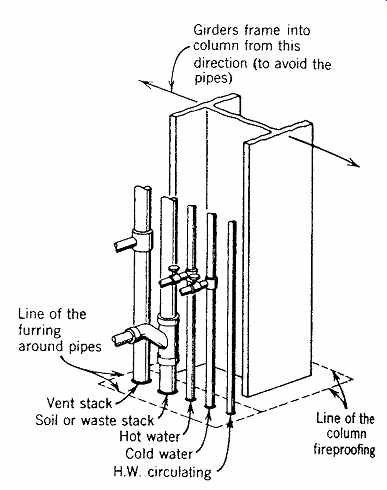
FIG. 27 Piping at a "wet" column. In large office buildings,
there are usually several of these, remote from the core, in the general office
area.
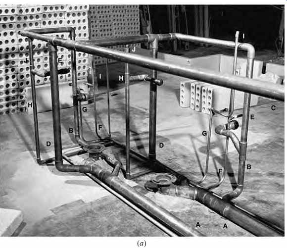
FIG. 28 (a) Horizontal waste piping above the structural slab, in an example
of plumbing roughing-in for two lavatory rooms in a concrete office building.
A lavatory and water closet (WC) in each room (see plan in b) are served by
soil and waste branches below and vent branches above. Hot and cold water tubing
with air chambers can be seen. Although the extensions of the water tubing
above the two flushometer connections appear to connect into the horizontal
vent branches, they actually do not; they are capped and merely touch the bottoms
of the vent branches. Note that soil branches are above the structural slab.
A fill of 5 or 6 in. (125 to 150 mm) is necessary to cover the tubing. All
vertical tubing will be within the masonry block used to enclose the cubicles.
(Courtesy of the Copper Development Association.)
(b) Roughing-In
This is the process of getting all pipes installed, capped, and pressure-tested before the fixtures are installed. An example of roughing-in for an office building is shown in FIG. 28. The roughing-in of supply and waste piping for school lavatories is shown in FIG. 29.
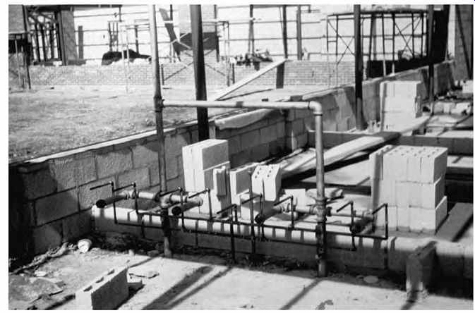
FIG. 29 Roughing-in for four lavatories in the toilet room of a school.
The waste branches have been capped and the system tested for leakage. The
waste branches are cast iron, the vents galvanized steel, and the water supply
lines are copper with soldered fittings.
At the center of the supply array are vertical capped expansion and shock tubes, one for hot and one for cold supply water.
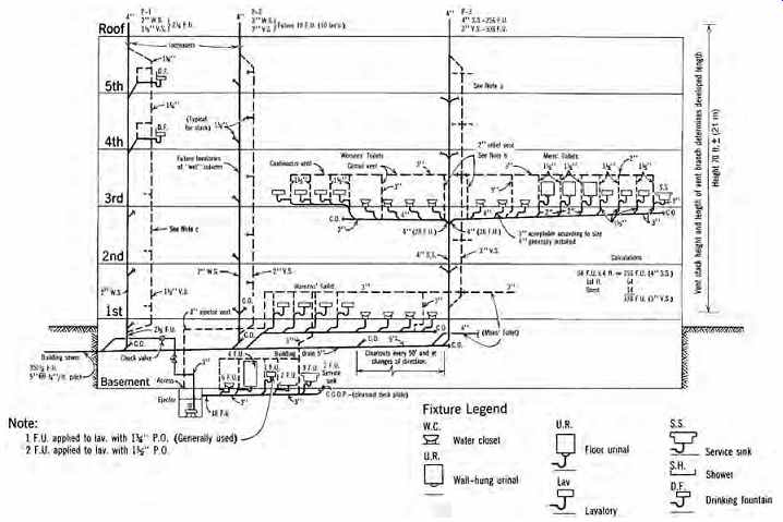
FIG. 30 Example 2. Plumbing section of an office building. Circuit vents
serve branch soil lines, but some codes require continuous venting (individual
fixture vents). The house trap and fresh-air inlet are omitted from the building
drain. Note that (1) a relief vent is not required on the top floor. (2) Men's
and women's toilets on the third floor are typical and would be repeated on
the first, second, fourth, and fifth floors. (3) Drinking fountains on the
fifth and fourth floors would be repeated on the first, second, and third floors.
Institutions such as schools have extensive requirements for durability and ease of maintenance. The fixtures are made of such wear-resistant materials as stainless steel, chrome-plated cast brass, precast stone or terrazzo, or high impact fiberglass. The fixture controls are designed to withstand heavy use-or mis use-and the fixtures are securely tied into the structure with concealed mounting hardware designed to resist extraordinary forces. (Some schools even move the lavatories into the hall way for better visual control of at least a part of the restroom facilities.) In prisons, extreme measures are taken to pre vent plumbing fixtures from becoming weapons or damaged. Heavy-gauge stainless steel fixtures with nonremovable fittings are provided, at very high cost, for both the fixture and its tamperproof installation.
EXAMPLE 2
Select drainage and vent piping sizes for the plumbing in an office building for which the fixtures are shown in FIG. 30.
SOLUTION
Selected dfu values from Table 2 are applied to each section of the piping and totaled for each branch and stack, as well as for the building drain and the building sewer. Individual fixture branches should not be less than the size indicated in Table 3 for the minimum size of trap for each fixture.
An example of a fixture-unit summary and sample sizes of individual branches that connect into a typical branch of the men's toilet group on any floor are shown in the following table.
Table 3 indicates that a 3-in. (76-mm) horizontal fixture branch is inadequate for the men's toilet group because this size pipe will handle only 20 dfu. Therefore, a 4-in. (102-mm) pipe is selected (also a wise minimum choice whenever water closets are served). Its capacity of 160 dfu will be more than enough for the 36 fixture units needed here.
The same table shows that the soil stack diameter can be 4 in. (102 mm), and it is run thus for its entire height. Its capacity of 90 dfu per story (or interval) is sufficient for the 64 dfu that connect in at each T-Y connection. For three branch intervals, this size stack will carry 240 dfu (this example requires 3 × 64 = 192 dfu); for its entire height, it will carry 500 dfu (this example requires 5 × 64 = 320 dfu).
The vent stack must serve up to 338 dfu, with a 4-in. (102-mm) soil stack, and with a maximum 70-ft (21.3-m) developed length. From Table 4, a 3-in. (76-mm) vent serving 540 dfu has a maximum developed length of 150 ft (45.7 m), well over the minimum requirements. All vent stack diameters will increase to 4 in. (102 mm) as they pass through the roof.
According to Table 5, the building drain and the building sewer, at a pitch of ¼ in./ft (2.1%), should carry at least a total of 350 dfu. A 5-in. (127-mm) building drain or building sewer has a capacity of 480 dfu.
Although opinions may vary about the relative merits of continuous or circuit venting, either system, properly designed, will effectively prevent the siphoning of traps and relieve air pressures that could cause foul gases to bubble through the traps into the occupied space. Another system (Section 5c), especially suitable for high-rise buildings, eliminates the vent stack completely with equal effectiveness.
(c) The Sovent System
This essentially ventless system changes the nature of the effluent (the wastes discharged from the fixtures) instead of coping with the pressures and suctions that normal effluent would cause (see Figs. 31 and 32).
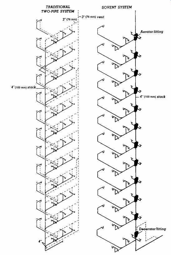
FIG. 31 Comparing a two-pipe system for a 12-story stack serving an apartment
grouping to the Sovent system. (Courtesy of the Copper Development Association.)
The "plunger" effect of a descending "slug" of water/waste within pipes was described in Section 2. If the "effectiveness" of the plunger can be reduced, the negative and positive pressures created by it will also be reduced. If their values can be brought down below the holding power of the several inches (mm) of water in the trap, no vents will be necessary. In the single-stack Sovent system illustrated in FIG. 32, this is done by dealing with the normal liquid effluent at each floor. Aeration there produces a foam that lacks the stack-filling tendency of unaerated liquid effluent. Thus, through the creation of a soft plunger, pressure variations in the single stack are minimized.
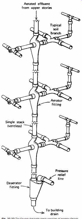
FIG. 32 The Sovent drainage stack consists of aerator fittings that join
the horizontal branches to the stack at each floor level and a deaerator fitting
at the bottom of the stack. The stack is open to the atmosphere above the roof
at the top. (Courtesy of the Copper Development Association.)
Tests have shown that the positive and negative pressures produced by normal liquid effluent during its descent (to be relieved by the vent piping) are often about 5 to 12 in. (127 to 305 mm) water gauge. If vents were not provided, the 2 to 4 in. (51 to 102 mm) of water seal in the traps would be vulnerable to penetration by gases from pipes under greater positive pressure (or siphonage of water seals into pipes that may be under negative pressure).
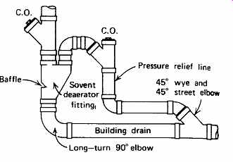
FIG. 33 The deaerator consists of an air separation chamber with an internal
nosepiece, a stack inlet, a pressure relief outlet at the top, and a stack
outlet at the bottom. The deaerator fit ting at the bottom of the stack functions
in combination with the aerator fittings above to make the single stack self-venting.
The deaerator is designed to overcome the tendency for the falling waste to
build up excessive back pressure at the bottom of the stack when the flow decelerates
at the bend into the horizontal drain. (Courtesy of the Copper Development
Association.)
Figures 31, 32, and 33 illustrate the components and the action of the Sovent system. Effluent, already aerated and descending from upper stories, is diverted in the stack at each lower story. The aerator fitting there affords a passage for this diverted flow and also an air space into which the effluent from the local branch soil or waste can drop. Here it spatters, mixing with air to form a rarefied mixture of air and liquid. Tests show that this mixture does not produce pressures, positive or negative, of more than 1 in. (25 mm) water gauge. Thus, a trap seal of 2 in. (51 mm) or more is safe against siphonage or penetration.
At the foot of the single stack the aerated effluent is compacted-a process aided by a baffle in the path of the flow in the deaerator fitting (see FIG. 33). If not relieved, air piling up at this point could cause pressures in the stack at the first floor.
An air-discharge pipe provides relief of air from the deaerator fitting to the upper part of the building drain, above the liquid flow.
The Sovent system was invented by Fritz Sommer of Switzerland, who tested it in a 10-story drainage test tower. Since its introduction in 1962, it has been installed and used in hundreds of buildings in Europe and Africa. Canada used the Sovent method in the Habitat apartments at the 1967 Montreal exposition. Sovent was first granted U.S. code acceptance in 1968 in Richmond, California.
Following this success, its code acceptance grew rapidly during the early 1970s. However, not all jurisdictions allow Sovent installations.