AMAZON multi-meters discounts AMAZON oscilloscope discounts
(cont. from part 4 )
10. PIPING, TUBING, FITTINGS, AND CONTROLS
(a) Piping, Tubing, and Fittings
The system of water supply piping or tubing should efficiently fulfill its purpose, be easily maintained, and interfere as little as possible with architectural form and function. Except in basements, in utility rooms, and at points of access to controls, the piping system is usually concealed. Stud-and-joist construction can provide space for concealment, but in concrete or masonry buildings, vertical and horizontal furred spaces must often be provided.
Water supply piping is subject to corrosion over time. When pipe materials corrode, they first lose some carrying capacity (due to increased wall roughness and perhaps buildup of materials) and ultimately fail. Sediment from corrosion can adversely impact plumbing fixtures as well. Steel piping is particularly subject to corrosion. In the nonferrous group, red brass and copper tubing are effective in providing corrosion resistance. Copper tubing is less expensive than brass, assembles more easily, and is not subject to dezincification (attack by acids on the zinc in brass). For use in handling aggressive waters, plastic is often a good choice. Like copper, it is light in weight and assembles with great ease.
For ferrous pipes and "iron pipe size" brass, threaded connections are used. The external, tapered thread on the pipe is covered with pipe compound and screws tight against the internal tapered thread of a coupling or other fitting. The solder-joint connection in copper depends on capillary attraction that draws the solder into a cylinder of clearance between the mating surfaces of tube and fitting.
This occurs after the surfaces are polished and fluxed and the parts placed in final position. They are then heated, and molten solder is applied to the circular opening where the fitting edge surrounds the tube, with a small clearance. Solder is then drawn into the cylindrical connection. Solders are often tin-antimony alloys. This kind of joint permits the advantageous setting up of an entire tubing assembly without turning the parts (as in threaded installations) and before the soldering commences.
For the same strength, copper tubing may have thinner walls than threaded pipes because no threads need to be cut into it. Its smooth interior surface offers low friction to flowing water. Although threaded and solder-joint connections are the most common in small work, there are many other types (Figs. 58 and 59 and Table 13). Ferrous pipes in the larger sizes are often welded or connected by bolted flanges.
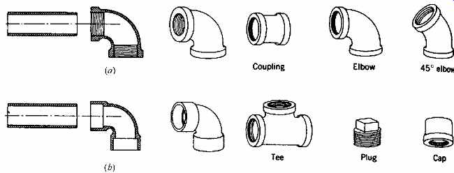
FIG. 58 Methods of connecting pipes and fittings, and tubes and fittings.
(a) Threaded: for ferrous pipe and fittings and for iron pipe size (IPS) brass.
(b) Soldered: for copper tubing and fittings. A sliding fit similar to that
of (b) is used for the solvent weld of plastic connections.
(b) Plastic Pipe
Most of the plastic pipes and fittings now produced are synthetic resins derived from such materials as coal and petroleum. These corrosion-resistant materials are widely used in water supply piping, fittings, and drainage systems. The National Sanitation Foundation (NSF) tests and certifies plastic pipe; the NSF seal must appear on pipes that are to carry potable water.
Most of the materials used for piping are thermoplastics and will repeatedly soften under the application of heat. PVDC (polyvinylidene chloride) material can carry water at 180ºF (82ºC), but plastic pipe should not be subjected to temperatures higher than this. Expansion (see Table 12) is much greater than that of other piping materials for the same delta t and affects the piping design. Quite shockproof, plastic is used in the plumbing systems of most mobile homes.

FIG. 60 Typical valves for water systems. (a) Gate valve.
(b) Globe valve. (c) Check valve. (d) Angle valve.
(c) Valves and Controls
It is usually desirable to valve every riser, the branches that serve bathrooms or kitchens, and the runouts to individual fixtures. This facilitates repairs at any location with a minimum of shutdown within a system. Water treatment equipment will have a valved bypass (see FIG. 52). Pumps and other devices that may need repair should be able to be disconnected by unions (FIG. 59) after valves are closed.
A gate valve (FIG. 60a), with a retractable leaf machined to seal tightly against two sloping metal surfaces when closed, offers the least resistance to water flow when open. It is usually chosen for locations where it is left completely open most of the time. The compression-type globe valve (FIG. 60b) is usually used for the closing or throttling of flow near a point of occasional use.
Faucets are usually of the compression type, as are drain valves and hose connections. They are similar to an angle valve (FIG. 60d). When it is necessary to prevent flow in a direction opposite to that which is planned, a check valve (Fig. 60c) is introduced. The hinged leaf swings to permit flow in the direction of the arrow but closes against flow in the other direction.
Table 13 Water Supply Piping Materials
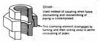
FIG. 59 Example of threaded pipe fitting (a union) for ferrous or brass
pipe. These and all common fittings are also available for solder-joint (copper)
or solvent-weld (plastic) connections and usually for transition from one system
or material to another.
(d) Pipe Support
Water piping systems are heavy because of their water content and need regular support (FIG. 61). Vertical runs of piping should be supported at every story. Horizontal pipes should be supported at intervals of 6 ft (1.829 m) for ½-in. (12-mm) pipe 8 ft (2.438 m) for ¾-in. or 1-in. (19- or 25-mm) pipe 10 ft (3.048 m) for 1¼-in. (32-mm) or larger pipe Although somewhat counterintuitive, these recommendations reflect the ability of larger pipe to span greater distances between supports. Horizontal copper tubing should be supported at closer spacing than steel. Adequate positioning of horizontal runs is important to ensure correct pitch and drainage.
Hangers are adjustable for this purpose.
(e) Shock and Hot Water Expansion
Expansion chambers were shown diagrammatically in Figure 52, and water hammer was explained in Section 9(b). Expansion chambers are often made of capped lengths of vertical pipe about 2 ft (0.6 m) long at the fixture branches (FIG. 62a). They trap air, which absorbs the impact of the water surge. A somewhat better (more controllable) device is a rechargeable air chamber (FIG. 62b). By closing the valve and draining the water through the hose bibb while the petcock above is open to admit air, the chamber may be refilled with air. Closing the petcock and hose bibb and opening the valve completes the service operation and reconnects the device with the water system. Rechargeable chambers (instead of pipe extensions) are used on branch lines adjacent to groups of fixtures. Access for ser vice must be provided. Perhaps the best device is the special shock absorber (FIG. 62c).
Air cushions also protect the water heater tank's relief valve against frequent operation, with the resultant leakage of hot water, as hot water periodically expands and contracts in closed systems.
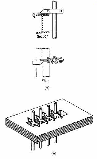
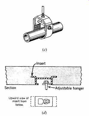
FIG. 61 Pipe supports. (a) Vertical riser supported at a steel beam. (b)
Vertical riser group supported at a slot in a concrete slab. (c) Horizontal
pipe hung from a slab above by an adjustable length clevis hanger. (d) Typical
metal insert in a concrete soffit to receive the hanger rod.
(f) Condensation or "Sweating"
The moisture that is always present in air can con dense on the exterior surface of a cold pipe. Drop ping off a pipe, it can create an unpleasantly wet condition, disfigure finished surfaces, and provide conditions amenable to mold growth. Groundwater in some parts of North America is 50ºF (10ºC) and colder (see FIG. 8.56). A pipe carrying such water might have a surface temperature of about 60ºF (15ºC). The psychrometric chart (Appendix F) indicates that at a summer air temperature of 85ºF (29ºC), condensation will occur on such a pipe when the relative humidity exceeds 40%. To avoid condensation damage, all cold water piping and fit tings should be insulated. Glass fiber ½ to 1 in. (12 to 25 mm) thick is commonly chosen for this purpose.
A tight vapor retarder on the exterior surface of the insulation prevents water vapor from penetrating the insulation and reaching the cold surface. The insulation provides another important advantage: it retards heat flow from the warmer air to the water, thus preventing the water from becoming disagreeably warm.
(g) Heat Conservation
Pipes carrying domestic hot water should be insulated to conserve energy used to heat the water and to ensure a correct water temperature at the points of use. Parallel hot and cold water piping, even though insulated, should be separated to prevent heat exchange. The pipe insulation should have a k = 0.22-0.28 Btu in./h ft 2 ºF, and its thickness should be a minimum of ½ in. (on pipes less than 1½-in. diameter) or 1 in. (on pipes 1½-in. diameter and above). In SI units, k = 0.032 - 0.040 W/m K, and the thickness should be a minimum of 1.3 mm (on pipes less than 25-mm diameter) or 2.5 mm (on pipes 25-mm diameter and above).
Storage tanks and water heaters are usually manufactured with integral insulation. Older devices, however, may have less insulation than today's energy concerns warrant. As a result, many older water heaters are retrofitted with added insulation. Some electric utilities find the savings from conservation so attractive (relative to the cost of building new generating facilities) that they provide water heater wrapping as a free service to customers.
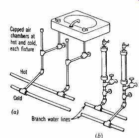
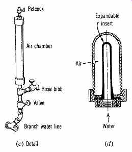
FIG. 62 Shock relief and expansion chambers. Air chambers cushion the shock
of the water hammer when the fixture faucets are shut off abruptly. They also
permit hot water to expand instead of periodically forcing open the hot water
emergency pressure relief valve at the heater or tank. (a) Capped air chambers
at each supply pipe of each fixture. (b, c) Rechargeable air chambers on hot
and cold branch water lines (individual fixture chambers are omitted when these
are used). (d) Special shock absorber.
Table 14 Flow and Pressure to Typical Plumbing Fixtures
11. SIZING OF WATER PIPES
There must be sufficient pressure at fixtures to assure the user of a prompt and adequate flow of water. Municipal ordinances often state that the flow must be adequate to keep the fixtures clean and sanitary. These convenience and sanitation objectives result in prescribed pressures that must be maintained at the various fixtures to ensure the proper flow rates listed in Table 14.
Minimum fixture pressures vary from 4 to 20 psi (28 to 138 kPa) for fixtures other than hose bibbs. Because the pressure in street mains is usually about 50 psi (345 kPa), it is possible to ensure the minimum fixture pressure, provided that the water does not have to be lifted to too great a height and not too much pressure is lost by friction in distribution piping. Excessive friction results from piping that is too long in developed length (actual distance of water flow) or that interposes too many fittings (such as elbows and tees), or is too small in diameter.
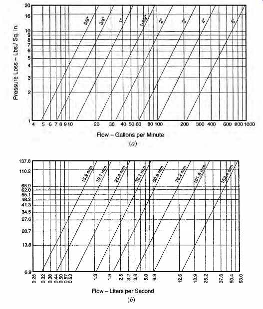
FIG. 63 Pressure losses in disk-type water meters. (a) I-P units. (b) SI
units. (Reprinted by permission from the 1997 Uniform Plumbing Code. © by the
International Association of Plumbing and Mechanical Officials, Walnut, CA.)
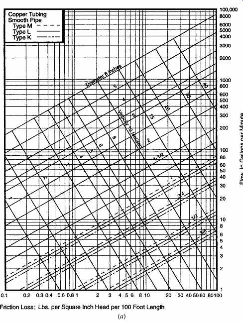
FIG. 64 Friction loss chart for smooth pipe: (a) I-P units; (b) SI units.
Velocity is shown to assist in noise control efforts: above 10 fps (3 m/s),
moving water can be clearly heard within pipes. (Reprinted by permission from
the 1997 Uniform Plumbing Code. © by the International Association of Plumbing
and Mechanical Officials, Walnut, CA.)
The pressure losses in an upfeed system served by street main pressure are as follows. For A in the following chart, use the highest, most remote fix ture from the main.
Minimum fixture flow pressure A Pressure lost because of height + B Pressure lost by friction in piping + C Pressure lost by flow through meter + D Total required street main pressure = E During design, items A, B, and E are known and are reasonably constant. A value for A can be found in Table 14. Street main pressure, E, is a characteristic of the local water supply and is obtained from the water utility. Item B, the pressure lost due to height, can be found by multiplying the height in feet by 0.433 (height in meters by 10) (see the discussion of static head in Section 9a). Item D, the pressure lost in flow through the water meter, depends upon flow and pipe size (FIG. 63), neither of which is yet known. Therefore, the value of item D is estimated. (For residences and small commercial buildings, meter size rarely exceeds 2 in. [50 mm].) Later, it must be checked and a recalculation made if necessary. This leaves one unknown, the value of C, where C = E - A - B - D Pipe size is based upon FIG. 64. Pipe diameter is determined by the point of intersection of a horizontal line representing flow and a vertical line expressing friction loss. To select a pipe size, one needs to know the probable flow and the unit-friction loss in the pipe and fittings. The noise created by water flow also must be considered. Flow above 10 fps (3.1 m/s) is usually too noisy; flow above 6 fps (1.8 m/s) may be too noisy in acoustical-critical locations.
Flow can be found for any pipe by first listing all fixtures to be served by that pipe, assigning them water supply fixture units (wsfu, listed in Table 15), and finding the total wsfu. This total is then converted to the likely demand flow in gpm from FIG. 65a (demand flow in L/s from FIG. 65b). These curves show that actual flow does not increase in direct proportion to an increase in fixture units. The larger an installation, the less likely that many fixtures will be operating concurrently. This reflects the statistical concept known as diversity.
To establish the desired friction loss, divide value C (pressure lost by friction in piping) by the total equivalent length of the piping. This length is the sum of the developed length (total linear distance of water travel) and the length equivalent of the fittings. For example, Table 16 shows that, in a 1-in.-diameter (25-mm) pipe run, a 90º ell causes a friction loss equivalent to that of 3 ft (0.9 m) of straight pipe. The number and style of fittings are estimated, and the size of fittings is assumed. This may be puzzling, but it is a common trial-and-error engineering procedure that sometimes requires several recalculations.
[...] ensures 15 psi at the critical fixture. The unit-friction loss, psi/100 ft of pipe, will be 14 psi × 100/150 (total equivalent length) = 9.33 psi/100 ft.
From FIG. 65a, curve 1, a flush-valve system with 85 wsfu will have a probable flow (diversified demand) of about 64 gpm. Given this information, enter FIG. 64a horizontally at 64 gpm and vertically at 9.3 psi/100 ft. At the intersection of these lines, the pipe diameter and velocity are determined. Between 1½-in.- and 2-in.-diameter pipe:
velocity = 8 fps (less than 10 fps, so OK) Therefore, a 2-in.-diameter supply pipe will be chosen with a 2-in. meter.
Now find the actual pressure loss in the 2-in. meter for a flow of 64 gpm. Figure 21.63a shows that this is about 4 psi. Because this is less than the 8 psi estimated, the pressure at the fixture will be slightly higher than the minimum needed. When a final system layout is made, the actual fittings are tabulated and the equivalent length of fittings is found. If this differs greatly from the 50 ft estimated, a recalculation is made. ¦
As in Example 6, the actual system pressures can be found using the exact pressure loss in a 51-mm water meter.
12. IRRIGATION
The highest design priority for landscape watering is to ensure optimum rainfall retention. In the past, provision for watering the landscape around buildings frequently was limited to the installation of hose bibbs at building exteriors. In many areas of North America, half of the residential water usage (see Section 22) is for outdoor purposes. With increasing demands on a finite water supply, water-conserving irrigation equipment has become available.
Lawn sprinklers are relatively inefficient irrigating devices, as much of their water is lost to evaporation and runoff. It is commonly estimated that lawn sprinkling will provide ½ in. of water per hour per square foot of lawn (or 0.3 gph per ft 2) (0.005 L/s per m2).
Landscape sprinkling is least efficient during the daytime, when hot sun and dry air combine to increase the rate of evaporation. However, night time sprinkling is rarely convenient for building custodians or homeowners. One solution to this problem is the use of sprinkler timing devices (Fig. 66a), which control electronic valves and a net work of underground supply pipes and sprinkler heads that are permanently installed within landscaped areas. These timing devices typically include controls governing the length of the watering cycle, the time at which the cycle begins (usually before sunrise, when relative humidity is highest), and the number of days between cycles. A "rainy day switch" is often included so that irrigation can be discontinued during rainy weather. Rain sensors can be used to shut off irrigation automatically (Fig. 66b). Tighter control over the water-plant relationship can be obtained with tensiometers (FIG. 66c), which monitor the moisture content of the soil at the depth of the plants' root zone. These can be installed so as to override the automatic timing device, thus watering more-or less- frequently, depending upon the plants' needs.
Instead of sprinklers, bubblers (FIG. 66d) can be installed, with very low flow rates and less evaporative water loss.
Table 15 Water Supply Fixture Units (WSFU)
EXAMPLE 6
Using the following data-some based upon the assumptions referred to previously- find the proper size for a metered water supply main.
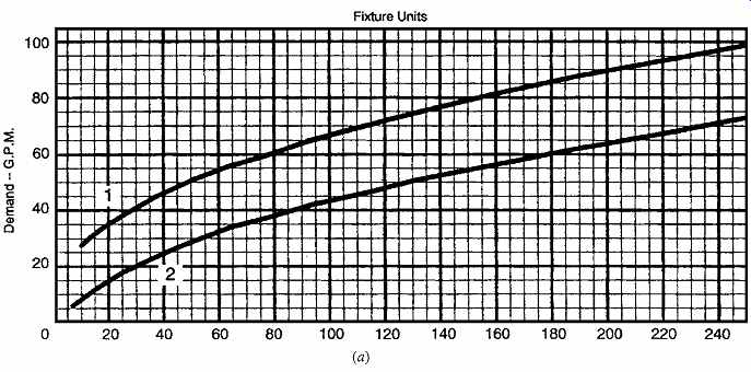
FIG. 65 Estimate curves for flow based upon total water supply fixture
units: (a) I-P units; (b) SI units. Within either chart, curve 1 is for a system
with predominantly flush valves; curve 2 is for a system with predominantly
flush tanks. (For fixture unit totals above 250, see the 1997 Uniform Plumbing
Code.) (Reprinted by permission from the 1997 Uniform Plumbing Code. © by the
International Association of Plumbing and Mechanical Officials, Walnut, CA.)
Table 16 Allowance in Equivalent Length of Pipe for Friction Loss in Valves and Threaded Fittings
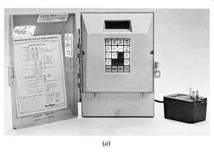

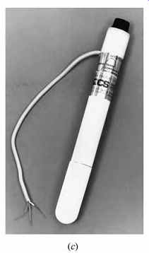
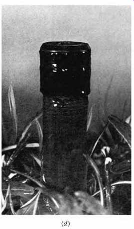
FIG. 66 Components for automatic landscape sprinkling systems. (a) Programmable
controllers feature multiple stations, up to 14 day sequences, and memory provisions
in case of power failure. (Courtesy of Rain Bird Sales, Inc.) (b) A solid-state
rain sensor automatically prevents needless watering during rainfall. (c) A
tensiometer controls irrigation by monitoring the moisture content of the soil.
(Courtesy of Water Conservation Systems, Inc.) (d) Bubblers are low-flow substitutes
for sprinklers-a step toward drip irrigation.
These can be pressure-compensating to permit constant flow. (Courtesy of Rain Bird Sales, Inc.)
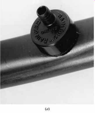
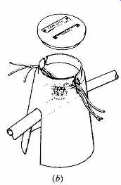
FIG. 67 Equipment for drip irrigation. (a) On low-pressure lines, emitters
are installed-one for each group of plants to be watered. The lines can be
laid on the ground surface or just under the surface. (b) Simple emitter boxes
allow easy access. (Courtesy of Rain Bird Sales, Inc.)
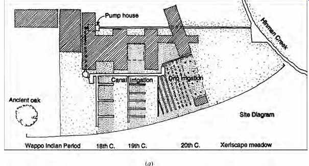
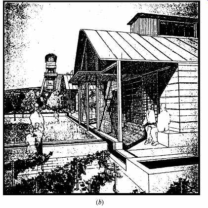
FIG. 68 The Napa Valley Museum shows the history of irrigation in northern
California. (a) Site plan. Water, piped from behind a small dam in the adjacent
creek, flows through open canals, then provides drip irrigation, eventually
discharging to a field of native plants. (b) The canals help guide the visitor
through the exhibit gardens. (Courtesy of Fernau and Hartman, architects, Berkeley,
CA.)
Drip irrigation takes an approach very different from that of the flooding method typical of sprinklers. From a network of plastic tubes, either just underground or on the surface, emitters (FIG. 67) slowly and steadily drip water onto the ground surface at each needy plant. Most of this water soaks into the soil at a rate that is better for most plants than the sudden, short flooding of intermittent sprinkling.
Two requirements are especially important for drip systems: the water must not contain materials that can clog the small holes of the emitters, and the pressure must be low. Pressure-reducing valves at the source of the drip system are advisable; if necessary, filters should also be installed there.
Drip irrigation is not a universal solution to landscape watering; it is best for individual plants such as shrubs and small trees but is difficult to apply to large lawns. Where appropriate, it can achieve significant water conservation compared to sprinklers. A detailed discussion of soil texture, moisture, and plant growth is provided in Lowry (1988, Chap. 4).
Recycled or reclaimed water for irrigation, often provided by graywater systems and sometimes by stored rainwater, is gradually gaining acceptance in North American building codes. This topic is explored further in Section 22.9. Considered non potable, this water must sometimes be deliberately colored and/or be accompanied by warning signs at each outlet.
Irrigation, past and future, shaped the design of the Napa Valley Museum in California (FIG. 68). An adjacent creek provides water behind a small dam. A pump house carries water to a central observation tower, where visitors see the history of irrigation displayed in the context of the Napa Valley.
The path of water in this model landscape invites visitors to explore canal irrigation of the eighteenth and nineteenth centuries, as well as advanced drip irrigation and xeriscape plantings of the twentieth century and beyond. (Xeriscape planting, as a part of the hydrozone landscape concept)
References and Resources
ANSI. 1986. American National Standard for Buildings and Facilities A117.1-1986: Providing Accessibility and Usability for Physically Handicapped People, American National Standards Institute. New York.
ASHRAE. 1995. ASHRAE Handbook-HVAC Applications. American Society of Heating, Refrigerating and Air-Conditioning Engineers. Atlanta, GA.
Banham, R. 1969. The Architecture of the Well-tempered Environment. Architectural Press. London.
Brown, G. Z., J. Reynolds, S. Ubbelohde. 1982.
Inside Out: Design Procedures for Passive Environ mental Technologies. John Wiley & Sons.
New York.
HUD. 1977. Intermediate Minimum Property Standards Supplement. U.S. Department of Housing and Urban Development. Washington, DC.
IAPMO. 1997. Uniform Plumbing Code. International Association of Plumbing and Mechanical Officials. Walnut, CA.
ICC. 1997. International Plumbing Code. International Code Council. Falls Church, VA.
Kira, A. 1976. The Bathroom, new and expanded ed. Viking Press. New York.
Lowry, William P. 1988. Atmospheric Ecology for Designers and Planners. Van Nostrand Reinhold.
New York.
Milne, M. 1976. Residential Water Conservation. U.S. Office of Water Research and Technology, Department of Commerce, NTIS.
National Drinking Water Clearinghouse, Tech Brief Series. U.S. Environmental Protection Agency.
Washington, DC:
June 1996. Disinfection September 1996. Filtration February 1997. Corrosion Control May 1997. Ion Exchange and Demineralization Plante, R. H. 1983. Solar Domestic Hot Water: A Practical Guide. John Wiley & Sons. New York.
Reif, D. K. 1983. Passive Solar Water Heaters. Brick House Publishing. Andover, MA.
U.S. Architectural and Transportation Barriers Compliance Board. Americans with Disabilities Act ( ADA) Accessibility Guidelines for Buildings and Facilities. Washington, DC.
The United States Access Board (accessible design):
http://www.access-board.gov/ U.S. Environmental Protection Agency. 1975.
Manual of Individual Water Supply Systems. Washington, DC.