AMAZON multi-meters discounts AMAZON oscilloscope discounts
(cont. from part 3 )
7. FIXTURES AND WATER CONSERVATION
Building design and fixture choice can affect water and energy consumption over the life of a building.
It is the users who turn the faucets on and off, but the designer who can encourage resource conservation through initial decisions, here centered largely in kitchens and bathrooms.
Visible consumption is one strategy to encourage the users of fixtures to conserve water. We see, hear, feel, and sometimes taste water as it issues from a fixture. If we could see how much water is involved in each use, we could more readily alter our pattern of use to conserve water where appropriate. Rainwater storage tanks outside bathroom windows, used to flush toilets, might have a visible indicator of the water level; the lower this level, the more that conservation is an imperative. The water-level indicator might be as simple as visible condensation on the tank's outer surface. Small, transparent tanks of clean supply water could be placed above lavatories, filled only when empty by means of a simple float valve. The user might thus be encouraged to use only a portion of the water already in the tank. Sufficient pressure at the fixture is achieved by such a tank's elevation above the fixture. The designer might also consider making the quantity of used (waste) water visible, but such water is often unsightly and the resulting quantity is "after the fact"-too late to conserve.
Audible consumption is another strategy, calling attention to the flow of supply (or waste) water.
This is achieved most simply by slightly undersizing water supply pipes so that the water velocity becomes audible (at about 10 fps [3 m/s]). This strategy should be carefully considered; it is one thing to inform the water user, another to annoy.
Audible flow is perhaps best justified on lines to exterior hose bibbs, where irrigation or car-washing hoses may inadvertently be left on.
Elimination of bodily wastes accounts for a significant portion of residential water usage (see Section 22), and bathing accounts for a significant portion of residential hot water usage (see Table 7). The choice of fixtures can have an impact on water conservation, and on energy conservation where hot water is involved. The bathroom is thus a site for potential resource conservation.
(a) Physiology, Psychology, and Fixtures
One of the more challenging aspects of bathroom design is the frequent conflict between physiological design criteria and such psychological influences as cultural attitudes about bathroom activities. Physiological criteria change as slowly as evolution. Cultural attitudes can change very rapidly, even within a generation. The bathroom supports two primary human activities: cleansing and elimination. Today's common attitudes about these closely linked activities are that one is "clean," the other "dirty." One might be discussed (although rarely) among friends; the other is simply not fit for conversation. This conflict in attitudes influences the design of our plumbing fixtures. The toilet is the fixture used for elimination; it is the logical place to provide for the cleansing of the perineal zone that should immediately follow elimination. (This is especially true of public toilets, where stalls close off toilets from lavatories.) Yet very few toilets presently incorporate a cleansing feature: the mixture of cleansing and elimination in the same fixture too often seems abhorrent.
The brief summary presented in this section is based largely on a particularly revealing (and entertaining) study of the struggle between physiological and cultural criteria in fixture and bathroom design-Alexander Kira's The Bathroom: Criteria for Design, an expanded edition of which was published in 1976 by Viking Press.
(b) Lavatories
A key issue here is the contrast between running water and a standing water body. Lavatories are used primarily for the cleansing of hands, face, and teeth-activities done quickly with running water that is wasted directly rather than being collected.
Most lavatories are designed as collection bowls- perhaps a reflection of the days when washbasins of standing water, drawn and heated elsewhere, were brought to the bathing place. Most lavatories also have fittings that project out over the sink.
Although these fittings have slowly evolved into very sleekly designed objects, most of them still dump running water directly into the drain, are hard to use as drinking fountains, and can wound those who try to wash their hair in the lavatory. In considering the prevalence of running as opposed to standing water, the role that running water could play in keeping lavatory surfaces clean, and the need for a drinking fountain when teeth are brushed, Kira proposed a quite different lavatory design (FIG. 38).
At full flow, lavatory faucets typically deliver 4 to 5 gpm (0.25 to 0.3 L/s). Newer low-flow faucets utilize a variety of devices to function as well (or better) with less water. Such devices include aerators (which add air bubbles to the stream, making it splash less and appear larger), flow restrictors, and mixing valves to control temperature. The lower flows achieved range from ½ to 2½ gpm (0.03 to 0.16 L/s). Another promising development is the foot-operated faucet, which frees the hands from having to control water flow, thus saving a few seconds of flow during each lavatory usage. These devices could be particularly helpful at kitchen sinks, where extensive washing of objects takes place.
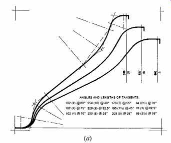
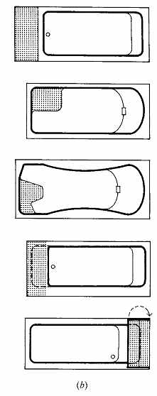
FIG. 39 Some considerations for tub design to facilitate relaxation during
whole-body cleansing. (a) A contoured backrest allows comfortable reclining,
with support of both the shoulder and lower back. Curve 2, with a median angle
of 32.5º, promises comfort for most users. (b) Various tub plans, allowing
long- and short-legged persons to brace their bodies against the con toured
backrest. Raised seats are also provided to facilitate safe entry/exit. (From
The Bathroom: New and Expanded Edition; © 1966, 1976 by Alexander Kira. By
permission of Bantam Books, a division of Random House, Inc. All rights reserved.)
(c) Whole-Body Cleansing
The running/standing water contrast is even more clearly illustrated here. In cleansing, the ordinary sequence is wet, soap, scrub, and rinse.
Standing water is good for wetting and very good for soaping/scrubbing; running water is superior for rinsing. The psychological aspect enters here in common attitudes toward tubs and showers.
Tubs are often seen as places to relax in, to spend more time in, and perhaps to read in. Showers are viewed as quicker, "no-nonsense," stand-up places. Yet each could benefit from some features of the other.
Tubs should be designed so that the reclining body is supported at the back; this requires a con toured surface (FIG. 39) rather than the ordinary straight-line design. It also requires braces for one's feet because otherwise the body will tend to float up and away from such a backrest. Tubs can be designed to accommodate persons of various leg lengths, as shown in FIG. 39b. There must also be a seat to give most of the body a chance to be out of the water and to facilitate safe entry into and exit from the tub. Especially needed is a handheld shower for the final rinse; soapy standing water leaves a scummy film on both people and fixtures.
Showers may seem very efficient, but cleaning would be more thorough and safe if the bather could turn off the water and sit for at least part of the soap/scrub activity, especially for the lower legs and feet. Showers with integral seats are now common.
Another consideration is the location of water controls (fittings). The user should be able to reach them easily from outside the tub or shower without wetting his or her arm, but also should be able to manipulate them from within the tub/shower even if temporarily blinded by soap.
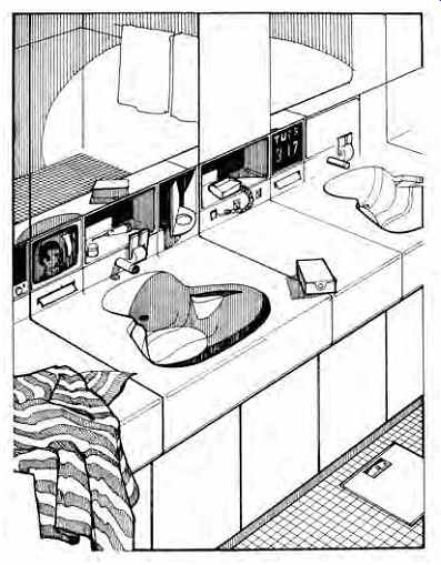
FIG. 38 Proposed lavatory that exploits running water. The water issues
from a fountain-like stream for ease in drinking and in hair and face washing.
The stream strikes the lavatory bowl in such a way as to minimize splashing
outside the bowl, yet sets up a self-cleaning swirling action. A small repository
at the back of the bowl, over the drain, can serve for standing water when
desired. (From The Bathroom: New and Expanded Edition; © 1966, 1976 by Alexander
Kira. By permission of Bantam Books, a division of Random House, Inc. All rights
reserved.)
Shower heads have been notorious for encouraging prodigal water usage; typical flow rates of 6 gpm (0.4 L/s) and maximum rates of 12 gpm (0.7 L/s) once were common. Even in a short (5-minute) shower, this rate of use could consume as much as 60 gal (227 L) of water, much of it heated. Many codes now require a limitation on showerhead flow; a flow of 2.5 gpm (0.2 L/s) is common. These flows can be designed into the shower head, or they can be achieved by cheap, simple flow restrictors in retrofit applications. Some utilities distribute flow restrictors free of charge. Most bathers notice no difference, either in enjoyment or in cleansing, when using restricted-flow shower heads.
(d) Elimination
Several conflicts arise with toilets: the already mentioned difficulty of combining cleansing with elimination, the issue of pure (high-grade) water for an impure (low-grade) purpose, and the conflict over the height of the toilet. A lower toilet is definitely of benefit to the average person, who will achieve far better bowel evacuation in a full squatting position. If combined with a toilet seat contoured to best support the body during defecation, the proposed toilet in FIG. 40a would be physiologically superior to most of today's fixtures. There are problems with low height. The typical male stands while urinating, and a lower toilet presents a more difficult target.
This can have serious maintenance consequences unless males can be induced to sit or a separate urinal is provided-an unlikely option for residential bathrooms. (In our culture, urinals look institutional; they are also expensive.) Another problem with a lower toilet is that the elderly and some handicapped people will have difficulty getting on and off the seat (see FIG. 51). Yet another problem arises from the fact that toilets are considered to be seats (for reading, toenail clipping, etc.). The low, squat-inducing toilet is decidedly not at a comfortable chair height.
As a result, a higher toilet with otherwise similar features is proposed (FIG. 40b). Note that both of these toilets feature openings whose shape differs from that of the conventional oval.
This hourglass-shaped opening provides proper support for the body during defecation, and it allows a more generous opening, front and back, for proper perineal cleansing by hand. Another change is that there is no separate toilet seat; instead, these fixtures incorporate electric resistance heaters that warm the small portion of the toilet that contacts the body. Thus, the toilet becomes a consumer of energy-which is also used to heat the water that is provided for perineal cleansing. For those who insist on a separate seat, or for ordinary posture on conventional toilets, a physiologically sound contoured toilet seat is available (FIG. 41).
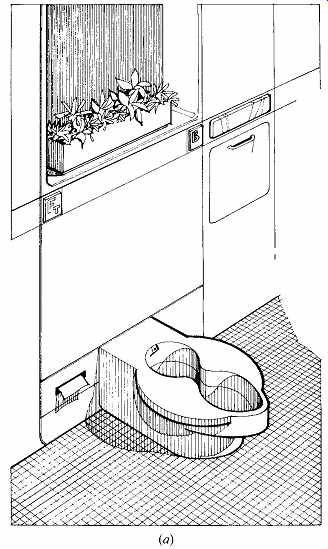
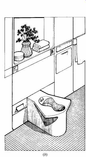
FIG. 40 Two approaches to water closets (toilets) that encourage better
posture during defecation and more thorough perineal cleansing. (a) A low toilet
allows the best (full-squat) position. (b) The higher toilet is easier for
the elderly and handicapped and better intercepts the urine from a standing
male. Both of these toilets eliminate the separate toilet seat and its maintenance
problems; both use small amounts of energy to warm the toilet at its point
of contact with the body and to heat the water for perineal cleansing.
Such cleansing is also the reason for the larger front and back openings. The pushbuttons are labeled FT for the flush and B for the bidet (cleansing) function. (From The Bathroom: New and Expanded Edition; © 1966, 1976 by Alexander Kira. By permission of Bantam Books, a division of Random House, Inc. All rights reserved.)
It is especially important that perineal cleansing be encouraged by the designers of bathrooms.
The typical dry toilet tissue provided usually is not adequate for this task. In small, private bathrooms this problem is easily solved by placement of the toilet adjacent to the lavatory (or tub), where toilet tissue can be wetted with clean water. In public toilets separated by stalls, perineal cleansing requires either a clean water source built into the toilet or a separate bidet within the stall-a highly unlikely provision, given the extra floor space and the cost of the bidet. Again, cultural issues arise: bidets are quite common in the private bathrooms of Europe but a rarity in North America. Two common alternatives are (1) to build a cleansing source into the toilet itself (FIG. 42) or (2) to construct a toilet seat that provides for such cleansing. Several American manufacturers offer such seats, which can be easily adapted to existing toilets. Using recycled water in a toilet that also offers perineal cleansing complicates the high grade water issue. Codes often require recycled water to be colored (blue or green), an aesthetic quality unappealing for skin contact even in one's nether regions.
The urinal is an answer to the problem posed by lower toilets to males, who stand while urinating. Although urinals are culturally acceptable in public toilet rooms, they have never achieved a place in private bathrooms. One solution proposed by Alexander Kira is to build the home urinal into the wall (FIG. 43a); it could be pulled out for use, at the optimum mounting height, and at an optimum receiving shape to eliminate backsplash onto the user. When pushed back into the wall, it would flush automatically. A less satisfactory solution would be to modify the toilet by raising its back surface (FIG. 43b).
For the toilet (water closet), there are four major categories of fixtures, depending upon the amount of water used per flush. The conventional toilet uses 3.5 gal (13.2 L) or more per flush; the water-saver toilet uses 1.7 to 3.5 gal (6.4 to 13.2 L) per flush; the low-consumption toilet (also called ultra-low flush) uses 1.6 gal (6 L) or less per flush; and the waterless toilet uses no water at all. (e) Conventional Toilets
These toilets may no longer be legally installed in the United States due to their high water consumption.
They are still widely encountered in existing installations. In the common toilet, a sudden deluge of water removes human waste and simultaneously helps cleanse the toilet. Fast-moving water requires pressure and makes noise. The older flush-tank toilet (FIG. 44a) stores a smaller quantity of water (about 2.5 gal [9.5 L]) at sufficient height above the toilet bowl to achieve fast flow. Although it uses minimal amounts of water, it is noisy and its elevated tank has maximum visual impact. The more common (in North America) version is the two-piece toilet with the tank bolted to the bowl (FIG. 44b). With much less pressure avail able, this toilet requires 5 to 7 gal (19 to 26 L) per flush, but it is quieter. Newer shallow-trap models reduce the quantity needed to 3.5 gal (13.2 L). The maintenance problem posed by the seam between tank and toilet is eliminated in the one-piece toilet (FIG. 44c). The cost of its low profile is an even greater need for water: 6 to 8 gal (23 to 30 L) per flush.
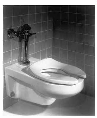
FIG. 41 Toilet seat for a conventional water closet, which encourages better
posture for defecation and somewhat better access for perineal cleansing. (Courtesy
of American Standard, Inc.)
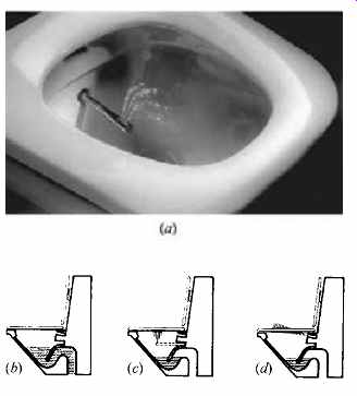
FIG. 42 Provisions for perineal cleansing built into toilets.
(a) An adjustable-intensity spray at warm (body) temperature continues for as long as a button is depressed in this Geberit Shower Toilet. (Courtesy of Geberit Manufacturing Inc., Michigan City, IN.) (b) Section through the toilet before/after the cleansing function. (c) At the initiation of perineal cleansing, a pipe extends and emits a controlled spray of warm water. (d) After the pipe is retracted, a warm jet of air issues from just below the seat. (From The Bathroom: New and Expanded Edition; © 1966, 1976 by Alexander Kira. By permission of Bantam Books, a division of Random House, Inc. All rights reserved.)
The fourth common alternative is the flush valve toilet, which depends upon the building's water pressure rather than its own stored water.
A noisy system requiring very high flow rates, it is seldom found in residences. However, it requires as little as 3 gal (11.4 L) per flush.
In addition to differing tank and bowl combinations, there are various types of flushing actions. Four common flush toilets are compared in FIG. 45.
Washdown toilets are no longer made in the United States, although many are still in use. This is the noisiest toilet and the most likely to become plugged because it has the smallest-diameter trap.
It is usually found in the two-piece flush tank toilet; with an elevated tank, the flush required was only about 2.5 gal (9.5 L).
Siphon jet toilets are in widespread use in North America, particularly in residences. A small priming jet hurries the bowl's contents into the trap and hastens the siphon action. With an elevated tank (two-piece) toilet, this process requires a flush of about 3.75 gal (14.2 L). With the more common close-coupled two-piece toilet, it requires a flush of 5 to 7 gal (19 to 26.5 L). Siphon jet toilets are sometimes equipped with flush valves, which use less water (see the discussion of blowout toilets that follows).
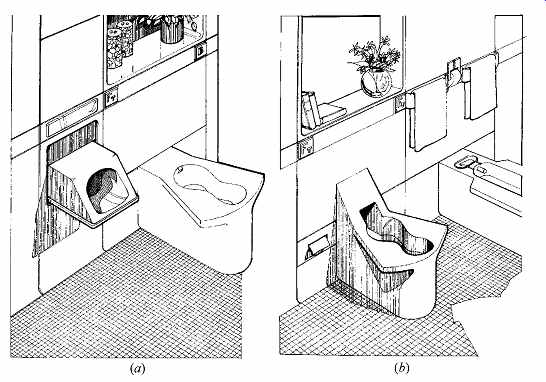
FIG. 43 Designs to accommodate male urination. (a) A built-in, tilt-out
urinal for the home, visible only when in use. (b) A higher back for a toilet.
A bidet for cleansing is shown to the right of the toilet. (From The Bathroom:
New and Expanded Edition; © 1966, 1976 by Alexander Kira. By permission of
Bantam Books, a division of Random House, Inc. All rights reserved.)
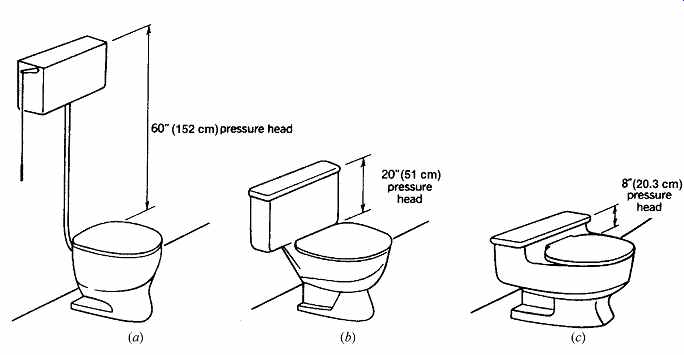
FIG. 44 Conventional flush tank toilets. (a) Two-piece flush tank toilet
with an elevated wall-mounted tank and pull chain. (b) Two-piece flush tank
toilet with the tank bolted to the bowl ("close-coupled"). (c) One-piece
flush tank toilet with an integral tank. (From Milne, 1976.)
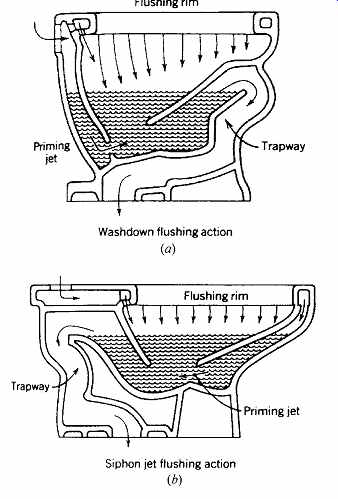
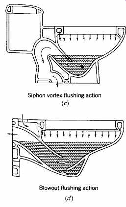
FIG. 45 Four common flushing actions that are built into toilets. Flush
tank toilets typically use either type (b) or type (c); flush valve toilets
use either type (b) or type (d). (From Milne, 1976.)
Siphon vortex toilets are especially suitable for low-velocity water (often as a result of low pres sure). They are therefore also the quietest, making them a favorite wherever bathrooms are adjacent to sleeping areas or other acoustically sensitive spaces. The water enters the bowl off-center in such a way as to form a vortex; this swirling action cleans the sides of the bowl and the trap, helping the siphon action in emptying both bowl and trap. The one-piece flush tank toilets usually have the siphon vortex flushing action, which typically requires 6 to 8 gal (23 to 30 L).
Blowout toilets combine very-high-velocity water and a simple trap to offer a noisy but very low-maintenance toilet dependent upon flush valves rather than tanks. They are very common in commercial and institutional toilet rooms, where large water supply lines and high pressures are available.
The high velocity of the water lowers the quantity required from 3 to 4 gal (11.4 to 15.1 L) per flush.
Architects can easily specify toilets that require less water per flush and yet have very little impact on the user. With effort on the part of both users and architects, water can be recycled, or rainwater collected, to supply toilets with lower-quality water.
(f) Watersaver Toilets
These use 1.7 to 3.5 gal (6.4 to 13.2 L) per flush.
Although these toilets use much less water than conventional ones, they may not meet the stricter water limits now established in many water conscious states and municipalities in the United States (toilets must not exceed 1.6 gal [6 L] per flush). Many of these toilets represent a compromise between the conventional "water waster" and the noisy operation and/or smaller water surface area that typifies so many low-consumption models.
Watersaver toilets tend to use a conventional flushing action, and hence need enough height between the tank and the bowl to provide sufficient water pressure within the bowl during the flush.
Toilets can be designed to use less water by varying several characteristics: the pressure of the water entering the bowl (generated either by the height of the tank above the bowl or by utilizing pressure from the water supply system or another source), the shape of the bowl, the way in which the bowl fills and empties, and the trap configuration. Watersaver toilets differ somewhat in most of these characteristics from a conventional toilet; more radical changes are needed to achieve a low consumption toilet.
(g) Low-Consumption Toilets
These use 1.6 gal (6 L) or less per flush. A heated controversy over these ultra-low-flush water closets developed in the late 1990s due in part to steep price increases and consumer discontent over performance. It appears that regulation got ahead of technology for a time, resulting in a need for repeated low-consumption flushes to accomplish what one higher-consumption flush could do. To remove fecal matter, however, two 1.6-gal (6-L) flushes still approximately equal the old 3.5-gal (13.2-L) flush; to flush urine, one 1.6-gal (6-L) flush is adequate.
Manufacturers are finding ways to change the entry point of water into the toilet bowl to increase swirl and thus waste-removal power.
Several of these toilets achieve water conservation by using a flushometer tank (FIG. 46). Satisfactory flushing can be achieved with much less water by flushing with water entering at greater pressure. Instead of toilet tanks at ordinary air pres sure, these tanks utilize water supply system pres sure to compress air trapped within the tank. Water enters the bowl with much greater force with this combination of water under system pressure and compressed air. The flush is thorough, quick, and noisy. If the water supply pressure is greater than about 65 psi (448 kPa), some problems with excessive tank pressures may be expected. A pressure reducing valve would be helpful in such cases.
Another water-saving technique is to redesign the bowl to hold less water. The siphon jet, gravity fed toilet whose tank is shown in FIG. 47 exposes a standing water surface of about 4½ × 6 in. (114 × 152 mm), much smaller than that in FIG. 46. Along with a very low 1.4-gal (5.3-L) flush, its trap is wide enough to pass a 21 8-in. (54-mm) ball.
Far lower water consumption is achieved when a central compressed air system is combined with water supply system pressure. The Microphor flush toilet (FIG. 48) uses compressed air and 2 qt (1.9 L) of water per flush in a two-chambered toilet. When the flush lever is pressed, the water and waste in the bowl (upper chamber) is deposited into the secondary (lower) chamber, and 2 qt (1.9 L) of water (direct from the supply pipe) washes down the sides of the bowl to await the next user. The now-closed secondary chamber then is pressurized with compressed air, and its contents are deposited into a conventional sewer line.
Air compressors are needed, along with com pressed air lines. A small compressor (¼ to ½ hp [187 to 373 W]) with an accompanying air tank will operate up to three toilets. Although the compressor is noisy, the toilets themselves are no noisier than conventional toilets; they use the same plumbing lines. With such low flows, the designer may choose to increase the slope of waste lines; however, the 2-qt (1.9-L) quantity has proven sufficient to carry the waste in existing installations.
In contrast, the Envirovac flush toilet (FIG. 49) uses a vacuum and 1.5 qt (1.4 L) per flush.
Because a central sewage tank (kept under vacuum by a pump) must be used, the drain line from the toilet to this tank may run horizontally without a slope or may even run vertically upward from the toilet. This can have significant architectural advantages when vertical clearance is tight, toilets are being added within existing structures, or toilets must be located below the level of the public sewer, as in marinas or basements. In tall buildings, significant savings in power for water supply pumping are achieved.
Easier approval for building permits, reduced water hook-up fees, and lower monthly sewer charges can be substantial benefits. Furthermore, the central
sewage holding tank can be flushed into the sewer at off-peak times-a benefit to the treatment plant.
These water-saving, architectural, and water treatment advantages must be weighed against the cost of the toilets and the tank/pump combinations, the space required for the tank/pump, the power used by the pump, and the possibility that a power failure will halt system operation.
FIG. 47 A very-low-flow flush is achieved with a reservoir that meters
about 1.4 gal (5.3 L) of water from the tank to the bowl during flushing. The
standing water surface is about 4½ by 6 in. (115 by 150 mm). The Ultra One/G.
(Courtesy of Eljer Industries, Plano, TX.)
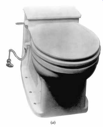
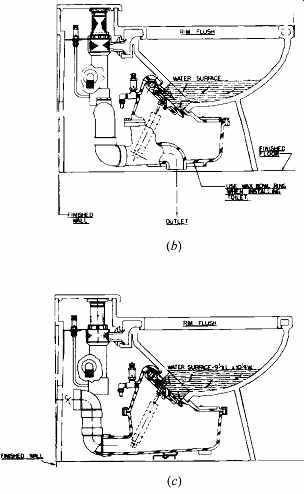
FIG. 48 (a) Compressed air is combined with a 2-qt (1.9-L) flush in the
two-chamber Microphor toilet. (b) Section through the floor discharge model.
(c) Section through the wall-discharge model. (Courtesy of the Microphor Company,
Willits, CA.)
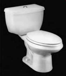
FIG. 46 Example of a 1.5-gal-flush (5.7-L), pressure-assisted, direct-fed
siphon jet flush action flushometer tank, with a large 10 × 12-in. (250 × 300-mm)
water surface area in the bowl: the Cadet Aquameter. (Courtesy of American
Standard, Inc., Piscataway, NJ.)
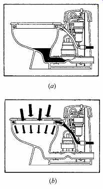
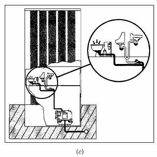
FIG. 49 The Envirovac system utilizes a vacuum and a 3-qt (1.4-L) flush.
(a) Less than 3 pints (1.4 L) of water remain in the bowl until the toilet
is used. (b) When the pushbutton flush is pressed, the discharge valve opens
for about 3 seconds; a rush of air into the evacuated piping carries along
sewage, odor, and airborne bacteria. Simultaneously, the washdown water flow
begins. The flow continues for 4 seconds after the discharge valve closes,
so that most of the 3-qt (1.4-L) flush remains in the bowl. (c) Toilets are
directly connected to a central holding tank, kept under a vacuum by a pump.
(d) Central tank/pump combinations can serve one house or a large building.
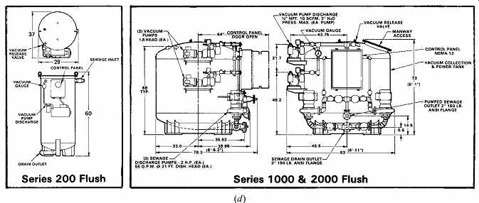
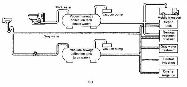
(e) The separation of graywater and blackwater is another water-conserving opportunity. (Courtesy of Envirovac, Inc., Rockford, IL.)
Vacuum systems can be installed for groups of buildings, such as subdivisions. Small pipe sizes, freedom from the need for continuous-sloping sewer lines, and conservation advantages for both water supply and treatment are the benefits. In addition, graywater (from kitchen, laundry, and bathing fixtures) can be kept separate from toilet water (blackwater) and thus made easier to recycle after moderate treatment.
(h) Flushing Controls
Water conservation is encouraged by the dual cycle toilet, whose flushing mechanism allows a choice of fewer gallons for liquid wastes, more gallons for solid wastes. This simple mechanism is still more commonly seen outside the United States; its handle is pushed up for liquid flushing and down for solids.
Another development is the automatic flush, common in public buildings and triggered by radiant heat from the pressure of a body at the fixture or by light reflected off the user and back to the control.
This "touchless" approach seems to promise more for hygiene than for water conservation, although it does prevent the flush valve from being held open too long by a careless user.
In general, plumbing fixtures will consume less water as the supply water pressure is reduced. For this reason, pressure-reducing valves are becoming popular as water conservation devices (when they would not otherwise be required to protect fixtures from overpressure). Installed on the supply line to a building, they can save water throughout the system.
Several newer low-consumption toilets use vertical flush valve sleeves, where the flush handle is in the center of the top of the toilet tank. The handle is lifted to initiate the flush. An advantage is that the less time the handle is raised, the less water enters the bowl. Again, less water may be admitted to flush away liquid waste, more water for solid waste.
(i) Waterless Toilets Because these fixtures eliminate water entirely.
(j) Appliances
Dishwashers, washing machines, and other appliances are big users of water-and of energy to heat it. Dishwashers use 12 to 18 gal (45 to 68 L) per cycle, much of it heated well beyond the 120ºF (48ºC) typical of a household hot water supply.
Some models now allow shorter cycles, which can cut use to perhaps 7 gal (26.5 L).
Clothes washing machines use 40 to 55 gal (151 to 208 L) for full-sized loads. In the past, "suds saver" features allowed soapy, hot wash water to be reused. Many newer washers allow for a wider selection of water quantities and temperatures-a feature that can save considerable water and energy. Horizontal-axis (front-loading) washers have greatly reduced the need for hot water per wash cycle.
8. FIXTURE ACCESSIBILITY AND PRIVACY
After plumbing fixtures designed for the human physique and for water conservation have been chosen, they are placed in a space that has several unusual environmental needs. Much of the information in this section is reproduced with permission from American National Standard for Buildings and Facilities A117.1-1986: Providing Accessibility and Usability for Physically Handicapped People, copyright 1986 by the American National Standards Institute (ANSI). Copies of this standard (updated as Accessible and Usable Buildings and Facilities in 2003) may be purchased from ANSI, 25 West 43rd Street, New York, NY 10036. Another useful guide is the Americans with Disabilities Act (ADA) Accessibility Guidelines for Buildings and Facilities, available from the U.S. Architectural and Transportation Barriers Compliance Board, Washington, DC.
(a) Accessibility
Designers must allow room for wheelchair maneuvering into and within toilet rooms. The minimum clear floor area should be a circle 5 ft (1.525 m) in diameter. Minimum clearances for wheelchair maneuvering are shown in FIG. 50. Provisions for people in wheelchairs also influence the heights at which items such as light switches, electrical receptacles, paper towels, and water controls should be installed. In general, all objects to be reached by hand in toilet rooms should be placed more than 15 in. (380 mm) and less than 48 in. (1.22 m) above the floor.
Floor space requirements and mounting height limitations also apply to the various plumbing fixtures in bathrooms, at least one of which (in each case) should be accessible to people in wheel chairs in most buildings. Requirements for drinking fountains (which often must be located outside toilet rooms), lavatories, bathtubs, and shower stalls include clearances beside the fixture (and clearance below lavatories) and grab bar locations; see the ANSI Standard for details.
Accessible toilets (water closets) have particularly large floor space requirements, as shown in FIG. 51. There is a conflict between the lower mounting height needed for proper defecation, the conventional height of 15 in. (380 mm), and the recommended height for handicapped users of 17 to 19 in. (430 to 485 mm). The doors on stalls designated for wheelchair access should swing out rather than in. Provision for a wheelchair sitting beside the out-swinging door must also be made.
No doors should swing into the clearance space required for any fixture.
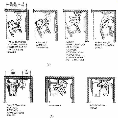
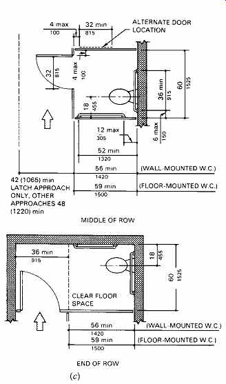
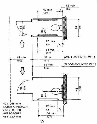
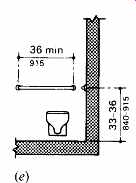
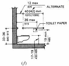
FIG. 51 Clearances and grab bars for toilets. Two typical approaches (a,
b) necessitate the stall clearances shown (c-f) as well as arrangements for
toilets and urinals not within stalls (g-i). (Reprinted by permission from
American National Standard A117.1 1986; © 1986 by the American National Standards
Institute.)
Where six or more water closets (or water closets plus urinals) are located within the same toilet room, both the "standard stall" (FIG. 51c) and one of the "alternate stalls" (FIG. 51d) are required.
This impacts the design of public toilet rooms.
Urinals for handicapped users should either be of the floor-mounted stall type or, if wall-hung, have an elongated rim at a maximum of 17 in. (430 mm) above the floor. A clear floor space of 30 × 48 in. (760 × 1220 mm) is required in front of the urinal, and its flush controls should be no more than 44 in. (1.12 m) above the floor.
(b) Privacy
A desire for visual privacy is easily understood and at least minimally provided by partial-height partitions. However, acoustic considerations are another important aspect of bathroom design. Because of their nonabsorbent surfaces, bathrooms are frequently the most reverberant spaces in a building.
They encourage the singer or the whistler and may even serve as practice rooms for the family musician. Yet they can also intimidate a person who prefers to be quiet, such as a guest using the toilet while the rest of the dinner party sits quietly in the adjacent room.
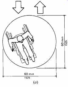
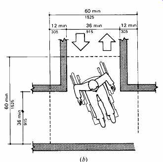
FIG. 50 Wheelchair turning space, minimum requirements. (a) A 60-in. (1.525-m)-diameter
space. (b) T-shaped for 180º turns. Dashed lines indicate the minimum length
of clear space required on each arm of the T-shaped space. (Reprinted by per
mission from American National Standard A117.1-1986; © 1986 by the American
National Standards Institute.)
Two common design responses are isolation and masking sound. Bathrooms can be separated from acoustically sensitive spaces by closets or hall ways. With careful attention to sufficiently massive construction and/or other construction details, the doors, walls, ceilings, and floors of bathrooms can be constructed so as to reduce the passage of sound to acceptably low levels. (These considerations are discussed in Sections 18 and 19.) Sound isolation also depends upon attention to detail: no cracks around the bathroom door, no back-to-back electrical outlets between bathrooms and adjacent spaces, no air grilles into ducts that have other grilles nearby, and no other open windows near a bathroom window. If such goals are unattainable or if additional acoustic security is desired, masking sound can be added as needed within the bathroom. All too often, the masking noise is provided by repeated flushings of the toilet (itself an embarrassing sound for some) or the running of water in the lavatory. However, a noisy ventilating fan would serve the purpose, as would a music source such as a radio. An elegant, expensive touch would be a recirculating fountain gracing one corner; it might provide splashing sounds only when the light or fan is on.
The final consideration in bathroom acoustics is the sound of water moving within pipes. Where such pipes are exposed or barely concealed within, or firmly attached to, thin walls, perceptible sounds are highly likely. Where water noise is undesirable, pipes should be wrapped, resiliently mounted, and/or located in a less acoustically critical wall. But remember that running water can also be a conservation signal as well as masking sound. Although many of us may have experienced this sudden acoustic signal that a bathroom is in use, few have experienced it quite like the occupants of the Aluminaire house on Long Island, cited by Reyner Banham (1969). Designed at the height of the modernist expression of mechanical services, this house featured a dining table cantilevered from the exposed waste stack serving the bathroom above.
9. WATER DISTRIBUTION
This section looks at ways to supply water through out buildings at pressures sufficient to operate plumbing fixtures. Smaller buildings may be served simply by the pressure available in water mains (or pressure tanks fed by pumped wells). This is called upfeed distribution, because the water rises directly from mains to the plumbing fixtures. For taller buildings, several other options are available: pumped upfeed (in which pumps supply the additional pressure needed); hydro-pneumatic (in which pumps force water into sealed tanks, compressing the air within; this maintains the needed water pressure); and downfeed (in which pumps raise the water to storage tanks at the top of a building, and water then drops down to the plumbing fixtures).
In cities with municipal water supply systems, water is distributed through street mains at pressures varying at the main from about 50 psi (about 350 kPa) to about 70 psi (about 480 kPa). For low-rise buildings of two or three stories, these pressures are adequate to act against the static pressure of water standing in the vertical piping, overcome the frictional resistance of water flow in the pipes, and still deliver water at the pressure required to operate plumbing fixtures. The flow pressure required at fixtures varies from 5 to 20 psi (35 to 138 kPa), depending on the type of fixture-for example, a basin faucet, showerhead and faucet, or water closet. (Table 14 in Section 11 lists minimum flow rates and pressures for typical plumbing fixtures.)
(a) Static Pressure
The pressure exerted at the bottom of a stationary "head" of water is related directly to its height.
One cubic foot of water weighs 62.4 lb. Consider a "cube" of water 1 ft square and 1 ft high. Its weight (62.4 lb) rests on a bottom area of 1 ft 2 (144 in. 2). The static pressure at the bottom is 62.4/144 = 0.433 psi (3 kPa). Reciprocally, 1 psi of pressure will sustain a static (stationary) column of water 1/0.433 = 2.3 ft in height. (In SI units, 1 m of head = 10 kPa.) When fixture pressure and pressure lost in friction-of-flow in pipes are considered, the problem becomes more complex. Example 6 in Section 11 illustrates this problem in the calculation of pipe size. For upfeed and downfeed distribution, the relationship of heights and static pressure is one controlling design factor.
(b) Upfeed Distribution
In small, low buildings of moderate water demand, it is seldom difficult to achieve the proper flow pressure at fixtures by the use of an upfeed system. Pressure at the fixtures is usually more than required. When this causes an inconvenient splash, as at lavatory basins, a flow restrictor can be used in the faucet outlet.
Consider the typical upfeed system shown in FIG. 52, beginning at the point where supply water enters the building. In cold climates, water in the service entry pipe must not freeze. The pipe must therefore be below the frost line of frozen ground.
This could vary from 0 to 7 ft (0 to 2 m), depending upon the geographical location. The onset of winter in cold climates requires the closing and draining of pipes supplying the hose bibbs (and other external piping) by means of a stop-and-waste valve. Houses left unheated in cold-winter weather must be entirely free of water that could freeze and burst the pipes.
Note the drain valve at every low point in the system.
House shutoff controls are usually located at the main, at the curb, and within the house.
Meters have recently taken on a new role: along with measuring the water quantity for which the occupant is to be charged, they now sometimes serve a restrictive function. During water shortages, they can be used to indicate water use in excess of established limits, beyond which fines are imposed and, in some cases, the water supply reduced by valves controlled by the water company.
In-house treatment is often performed to reduce water hardness that could clog piping and equipment or to neutralize acidity-a source of corrosion. During the short periods when the treatment tanks are valved off for backwashing or other servicing, the bypass shutoff valve is opened.
From this point on, the water continues under pressure to
1. Supply makeup water to the space-heating boiler, as required
2. Supply water to and pressurize the cold water mains and branches, including the garden hose bibbs
3. Supply water to and pressurize the domestic hot water system through the hot water heater, the hot water storage tank, and the mains, branches, and circulating lines
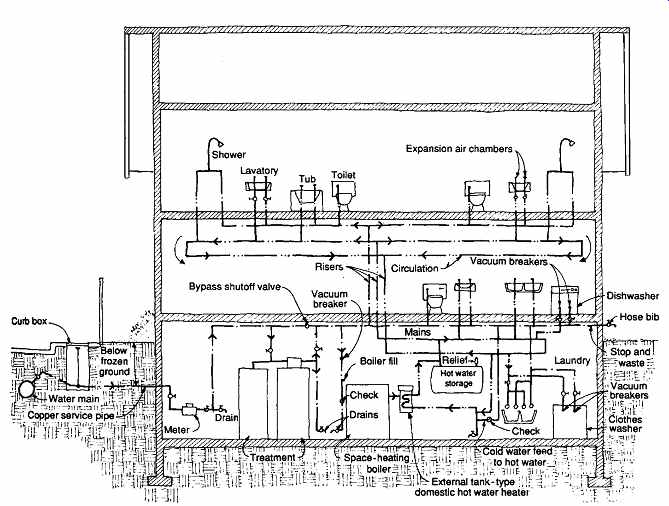
FIG. 52 Upfeed water distribution using pressure in street
mains. A schematic section of the water services in a typical residence.
The air-filled expansion chambers on cold water runouts absorb and reduce the shock of water hammer-the force exerted by decelerated flowing water that shakes and rattles pipes when faucets are shut off abruptly. On hot water runouts they perform the same function, as well as allowing for the expansion of the hot water as it increases in volume with increasing temperature. Vacuum breakers prevent backflow of polluted water into pipes carrying potable (hot or cold) water. Water from all fixtures and appliances, such as dishwashers, clothes washers, and boilers, is thus isolated.
Figure 52 shows all parts lying in a two dimensional plane. Obviously, in a real building, such a system is three-dimensional. For instance, economy of piping would suggest that, if possible, kitchen and lavatory, as well as the two upstairs bathrooms, be placed back-to-back.
(c) Principles of Downfeed Distribution
Water pumped directly from the street main (or from a basement "suction tank" filled by gravity from the main) is lifted to a roof-storage tank. In cold climates, the water in an outdoor tank is kept at temperatures above freezing by heating coils in the tank. The fact that water pressure increases with distance below the tank water level is clearly shown by the construction of the tank (shown in FIG. 53). The iron rings, tensioned by adjustable threaded clamps, become more closely spaced toward the bottom of the tank, where the greater water pressure makes it increasingly difficult to restrain the vertical wooden staves of this cylindrical barrel.
Tanks like these add interest, though perhaps not beauty, to a building's silhouette. A view blocking screen enclosing this tank would have to be about 24 ft (7.3 m) high. Architecturally, such a rectangular lump on the roof would not be much of an improvement. Yet in the century following the appearance of such structures as the Goodwill Building, our technology has become more complex.
Presently, for most high-rise buildings, including many 60 stories and more in height, an entire roof top crowded with equipment and technical facilities is needed to serve the stories below (or the upper most zone of a building). The items could include:
Water storage tanks
Two-story penthouses over elevator banks
Chimneys
Numerous plumbing vents
Exhaust fans
Air-conditioning cooling towers
Cantilevered rolling rig to support a scaffold for exterior window washing
Perimeter track for a window-washing rig
Photovoltaic cells and/or solar collectors for DHW
Thus, since the 1960s, tall buildings commonly have a band or screen two stories (or more)
high above the structural roof. The best view locations are thus consigned to mechanical equipment.
It might be said that it all began with the need for elevated water storage tanks.
(d) Tall Building Downfeed Distribution
Figure 54a shows a medium-rise building in which one elevated tank can serve all of the lower floors. For taller buildings, it is advisable to separate groups of floors into zones with a maximum height (for plumbing pressure limits) of about 150 ft (about 45 m). This zone-height limitation is based upon the height-to-static pressure relationship. At the top of the zone (about 35 ft [10 m] below the storage tank), the minimum desirable pressure is probably at least 15 psi (103 kPa). At the bottom of the zone, the maximum desirable pressure is perhaps 80 psi (552 kPa); above this pressure, damage to fixtures might occur.
80 psi - 15 psi = 65 psi difference
65 psi × 2.3 ft/psi = about 150 ft In SI units:
552 kPa - 103 kPa = 449 kPa difference
449 kPa × 0.1 m/kPa = about 45 m
With pressure-reducing valves at lower floors, how ever, these zones can be much higher, as shown in FIG. 54b.
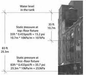
FIG. 53 Mid-rise building with gravity downfeed distribution.
Although upfeed distribution from a street main is possible in buildings higher than two or three stories, when street main pressures drop below the usual 50 psi (345 kPa), combined with heavy use, very low pressure results in fixtures in the upper stories. Therefore, water is pumped from the main to elevated wooden roof tanks high enough to ensure reasonable pressure at the top story and ample pressure at the bottom of the down feed run.
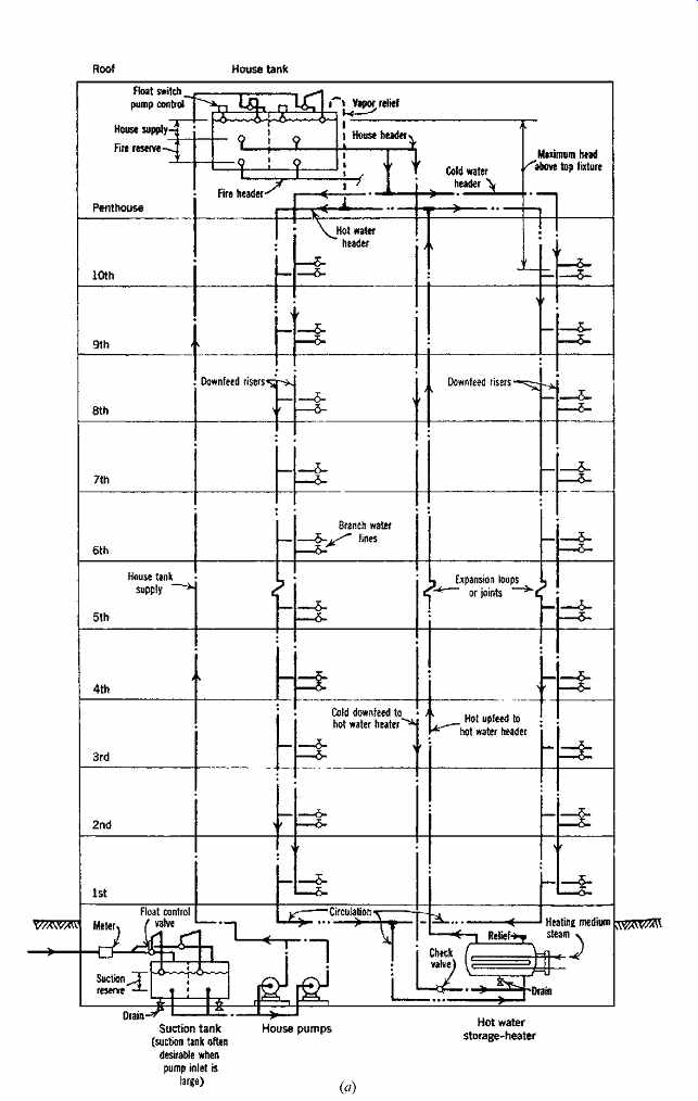
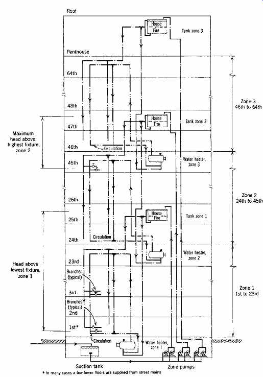
FIG. 54 (a) Downfeed water distribution, schematic section, part of the
water services for a 10-story building. Hot water circulation moves from the
hot upfeed in two directions at the hot water header, then down to the tank
through the two downfeed hot water risers. For details of one type of steel
house tank, a typical centrifugal house pump, expansion joints, and expansion
in the hot water riser, see Figs. 55 and 56. (b) Downfeed water distribution,
schematic section, part of the water services for a much taller zoned building.
Zone tanks include a fire reserve, but standpipes are omitted from this drawing.
For detail of the steam-type domestic water heater, see FIG. 24.
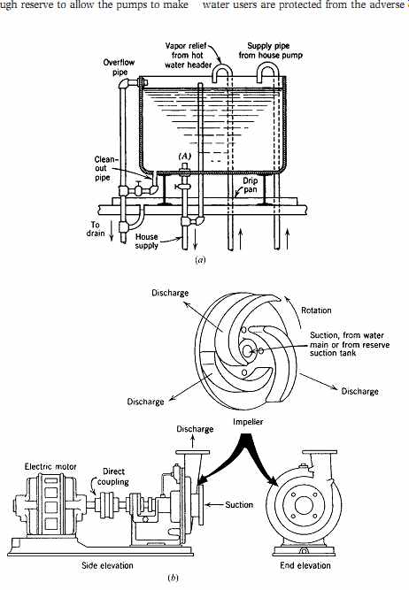
FIG. 55 (a) House tank in an elevated position for downfeed by gravity.
Sediment in the tank is drawn off through the clean-out pipe and is prevented
from entering the house water supply by the pipe projection at A. Water for
fire reserve could be provided by additional piping or by a separate tank.
(b) Centrifugal house pump, commonly used to fill an elevated house tank at
the top story or at an intermediate mechanical floor. The electric motor responds
to a float switch pump control at the tank.
Consider the system described in FIG. 54a, beginning with the elevated tank. The lower part of the tank often serves as a reserve space to hold a sup ply of water for a fire-extinguishing system. In this case, only the water in the upper part is available for use as domestic (service) water. The amount stored must be enough to supplement what the pump will deliver during the several daily hours of high demand that occur in most buildings. The pump then continues, often for several hours, to replenish the house supply that had become partially depleted during the busy period. The suction tank is a buffer between the system and the street mains. It usually holds enough reserve to allow the pumps to make up the periodic depletion in the house tank. It refills automatically by flow from the street main that, consequently, will not suffer as much of a drop in pressure as it would if it were connected directly to the suction side of the house pumps. Neighboring water users are protected from the adverse effects of sudden demands within adjacent large buildings (FIG. 55).
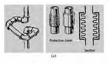
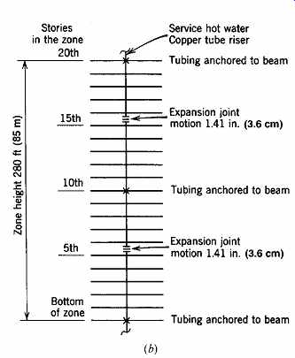
FIG. 56
(a) Accommodation for the expansion of hot water piping or tubing. Left: Expansion
joint of pipe and fittings. Right: A manufactured product in elevation and
section. (b) Suggested scheme for location of the points of anchorage and expansion
for service hot water tubing in a 20-story zone.
House tanks and suction tanks are sometimes made of steel plate and divided vertically in half, each half having identical piping and controls. Hence, one-half of the tank can be cleaned out at a time of low demand without shutting down the entire system. One full-capacity pump is supplemented by an equivalent standby pump for alternate use. Because there is no suction lift below the pump, or any fixture pressure at the top of the house tank supply, the head against which the pump works is the sum of the distance from the suction tank water level to the top of the house tank and the feet of head equivalent to the friction loss in the tank supply pipe. For this kind of service, the vertical piping is on the order of 3 or 4 in. (76 or 102 mm) in diameter for large buildings. Sizes are established by formal calculations.
The house supply is fed by a short pipe from the house header to the cold water header that circles the top story and connects to many downfeed cold water risers. For simplicity, FIG. 54a shows only two risers and also omits many valves and controls.
Figure 54b is even more simplified. The circulating hot water originates as cold water at the house tank header, then takes quite a long route.
Descending to the bottom of the hot water heater, it rises to seek its own level at the hot water header, becoming available there for hot water downfeed on demand. All of this occurs as flow below the general pressurizing effect of the house tank. In effect, when there is a cold- and hot-water demand on a story near the top of the building, the cold water makes a short trip down to the faucet, while the hot water goes through three vertical pipes instead of one.
This arrangement, with tank above and heater below, is used in multiple forms for very tall buildings. The zones are quite independent; the only common service is that provided by the general suction tank. With this zoning method, problems of pipe expansion, large pipe sizes, and high pressures in lower stories are minimized. Commonly, 2½ stories, or about 35 ft (about 10 m), constitute the minimum pressure head above the top fixture served by any zone tank. The static pressure created at the fixture is thus 35 × 0.433 = 15 psi (10 × 10 = 100 kPa). If, during flow, not too much pressure is lost in friction, flushometers (flush valves) can be placed at this level, although flush tanks, because of their lower pressure demand, must often be accepted.
The opposite problem occurs at the bottom of the zones, where excessive pressures must be reduced at the fixtures. In zone I of FIG. 54b, first-floor fixtures are below a head of 24½ stories, or about 149 psi (1027 kPa) of static pressure. Pressure reducing valves must be used, and fixture control valves must be throttled.
Table 12 Thermal Expansion of Pipe
(e) Pipe and Tube Expansion
The range of temperature experienced by hot water supply piping, from the normal indoor air temperature of about 70ºF (21ºC) to that of service hot water (which often exceeds 160ºF [71ºC]), can be 90Fº (50Cº), with resulting pipe expansion (Table 12). This longitudinal elongation of pipe, though negligibly small in houses, can be appreciable in a tall building. Two methods of allowing freedom for this longitudinal motion in long runs of expanding hot water piping are shown in FIG. 56a. These devices preclude the buildup of excessive stresses in the pipe material and the tendency of the pipes to buckle laterally.
EXAMPLE 5
A 20-story zone in a tall building has a height of 280 ft (85 m). What will be the increase in length of a copper tube carrying "service hot water" (DHW) when its temperature increases from 70º to 160ºF (21º to 71ºC)?
SOLUTION
The difference in temperature is 90Fº (50Cº). Approximate elongation per 100 ft for a 90Fº increase is 1.01 in. (interpolating in Table 12).
expansion = 280 ft × (1.01 in./100 ft) = 2.82 in.
(85 m × (0.83 mm/m) = 71 mm)
There are a number of ways of providing for this expansion. The one shown in FIG. 56b accepts this motion at two locations, which would make the expansion in each case 1.41 in. Equidistant anchorage to fix the tubing is provided at the bottom, the 10th floor, and the 20th floor. The sup port of the vertical riser at floors other than those at which it is anchored could consist of clamps of the type illustrated later in FIG. 61, supported on springs.
(f) Pumped Upfeed Distribution
This distribution system (FIG. 57) is for medium sized buildings-those too tall to rely on street main pressure but not so tall as to necessitate heavy storage tanks on the roof. The equipment associated with this system can deliver water at rates varying from those needed for two or three faucets to full building demand while maintaining at each outlet a pressure within 2 psi (14 kPa) of the design pressure for that outlet.
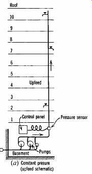
FIG. 57 Constant-pressure upfeed pumping (a, b) compared to gravity downfeed
from a house tank on the roof (c). (By permission of Progressive Architecture.)
The installation shown in Figs. 57a and 57b uses a triplex pump group. According to demand, one, two, or three pumps will operate.
Because each pump is of the variable-speed type, virtually an infinite number of delivery rates can be achieved within the zero to maximum design range. The pumps operate in sequence. When a very small rate of demand occurs, the smallest or "jockey" pump starts in response to a low voltage impressed on its motor. All operations are triggered and adjusted by the pressure sensor at the base of the riser. The jockey pump continues to run until it has reached its maximum delivery rate, at which time the first of the larger pumps cuts in, joined by the other larger pump when required. Sequential operation of the three pumps, each increasing in delivery as called for by the sensor, meets the requirement for an increasing supply at nearly constant pressure.
Wear on the two large pumps is equalized by the assigning of "lead" and "lag" positions. For a period of 24 hours, one of the large pumps holds the lead position and starts after the jockey pump, giving the other large pump a smaller burden. The next day the rested pump takes over the more active assignment. All of this occurs automatically.
At full operation, this triplex unit can put a suction demand on the street main that can seriously reduce the available water pressure in the neighbor hood (FIG. 57a). Therefore, utilities sometimes require that such a system draw from a surge tank, filled by casual flow from the street main, independent of the building requirements (FIG. 57b). This requirement is often imposed when analysis indicates a maximum building demand in excess of 400 gpm (25 L/s).
Obvious advantages of upfeed pumping are elimination of the house tank and the heavy structure that transmits its weight down to the footings, and elimination of the necessary periodic cleaning of the tank. A shortcoming is the lack of reserve storage, which could cause a serious problem during an electrical power failure. However, minimum flow during this kind of emergency can be arranged if a diesel or emergency standby motor is available to drive one of the pumps.