AMAZON multi-meters discounts AMAZON oscilloscope discounts
(cont. from part 2)
6. HOT WATER SYSTEMS AND EQUIPMENT
There are many ways to provide the "domestic" or "service" hot water needs within a building-the hot water used not for space heating, but for bathing, clothes washing, dishwashing, and other related functions. Whereas much of the world either heats such water on a cookstove or does without it, North Americans enjoy an array of choices for domestic hot water (DHW) supply systems. In this section, rough supply estimates are considered first, then basic design choices, conventional heater tanks, solar water heaters, and finally, energy recovery heaters.
With today's better-insulated buildings, the demand for space heating can fall to a level about equal to DHW. As a result, a trend is developing toward using one rather larger water heater designed to meet the need both for space heating and for DHW. This saves both floor space and equipment cost, compared to the more conventional boiler for space heating and a separate water heater for DHW. Some restrictions apply; the 1997 International Plumbing Code restricts the maxi mum water outlet temperature to 160ºF (71ºC) and requires water in such a heating system to remain potable.
(a) Water Temperature
Higher water supply temperatures have several advantages but carry the risk of scalding. Although water becomes uncomfortably hot to the touch above 110ºF (43ºC), much higher temperatures are often used for some commercial processes, as shown in Table 6. When determining the temperature at which DHW is to be supplied, consider the following factors.
Table 6 Representative Hot Water Temperatures
High Temperatures
• Allow the installation of smaller storage tanks (less hot water is mixed with cold water to achieve a final usage temperature at the shower, sink, or lavatory) but require larger heating units.
• Can be achieved at the point of use (rather than in the tank) by heaters built into equipment such as dishwashers.
• Can cause scale to form on heating coils and within piping (above 140ºF [60ºC] in areas of hard water quality).
• May be required by code for some applications but limited by code for others.
• Limit the potential for growth of Legionella pneumophila bacteria (above 140ºF [60ºC]).
Lower Temperatures
• Are less likely to cause burns but may not achieve desired sanitation.
• Mean less energy consumed, because storage and pipe heat losses are lower.
• Allow the installation of smaller heating units but require larger storage tanks.
• Make possible the use of lower-grade heat sources for DHW, such as solar energy or waste heat recovery. Table 2.1 shows that around 13% of annual U.S. energy usage is for DHW, which requires the lowest-grade heat source of all the common usages.
(b) Heat Sources and Methods
These include familiar concentrated-energy, high grade sources such as natural gas and electricity.
Oil- and coal-fired boilers are frequently equipped with DHW coils as well. Buildings served by steam may use steam as a DHW heat source. Cogeneration provides heat for DHW, as in FIG. 10.67. Because of the relatively low-grade final temperatures needed, DHW can also be readily provided by wood-burning equipment, incinerators, solar energy equipment, heat pumps, and heat recovery devices (as in commercial ice-making machines whose discharged heat is contributed to DHW).
Heating Methods. There are two basic methods:
1. Direct heating brings water in contact with directly heated surfaces: electric-resistance elements or other electrically warmed surfaces within tanks, or surfaces directly exposed to fire or hot gases.
2. Indirect heating can be accomplished in several ways. Coils containing steam or fluids can be submerged within water tanks or (FIG. 16) set within boilers, whose primary function usually is to provide space or industrial process heating. Alternatively, coils containing DHW can be placed outside a boiler but within a casing containing steam, hot exhaust gases, or very hot water.
Direct and indirect methods can be utilized in a variety of equipment:
Storage tank water heaters, the type most commonly used for residential and small commercial purposes (see Section 6h) Circulating storage water heaters, in which the water is first heated by a coil, then circulated through a storage tank (as in some solar heaters-see Section 6i) Tankless (instantaneous) heaters, in which the water is very quickly raised to the desired temperature within a heating coil and immediately sent to the point of usage
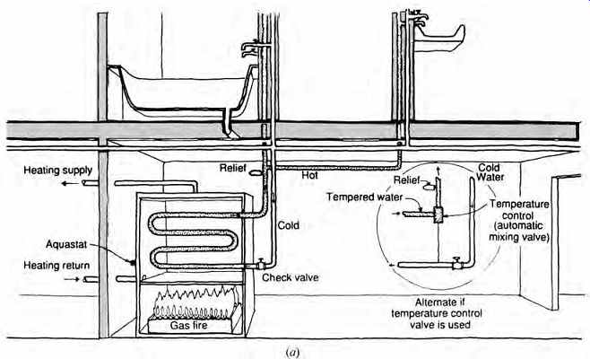
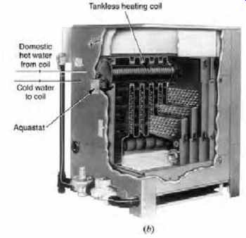
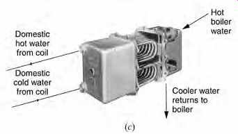
FIG. 16 (a) Example of an indirect, tankless heater for DHW utilizing a
boiler that provides hot water for space heating. Because no storage is used,
the point of DHW use should be very close to the boiler. (b) Internal tankless
heating coil for DHW immersed in the jacket water of a gas-fired hot water heating
boiler. The approximate capacity range is 3 to 15 gpm at a 100Fº rise (0.2 to
0.9 L/s at a 55Cº rise). (c) External-type tankless heater for DHW. Boiler water
is piped to the unit and circulates by gravity, transferring heat to the coil.
The approximate capacity range is 3 to 15 gpm at a 100Fº rise (0.2 to 0.9 L/s
at a 55Cº rise). Note: Because it can be highly inefficient to provide summertime
DHW with a boiler designed for winter space-heating loads, codes may alter or
prohibit this arrangement.
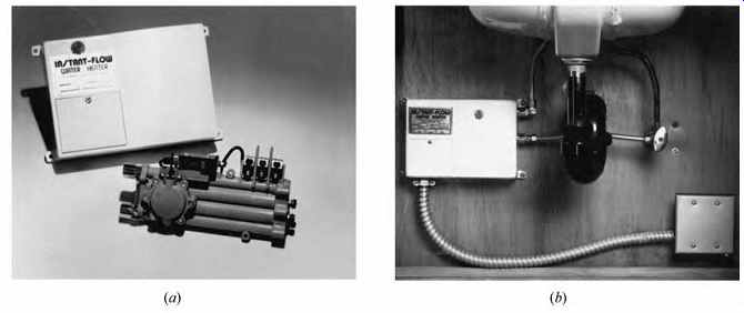
FIG. 17 Instantaneous or tankless water heater. (a) In this instant-flow
water heater, a series of coils heats water as it flows through. (b) Installation
below a typical lavatory. A wide range of sizes is available; the 4.6-kW unit
raises water by 31Fº (17.2Cº) at 1 gpm (0.06 L/s); the 9-kW unit raises water
by 61Fº (33.9Cº) at 1 gpm (0.06 L/s). (Courtesy of Chronomite Laboratories,
Inc.)
(c) Tankless Water Heaters
Also called instantaneous water heaters, these are available in larger sizes for central hot water systems (FIG. 16) or in smaller sizes for wall mounting adjacent to remote plumbing fixtures that occasionally need hot water, or for isolated bath rooms, laundry rooms, and so forth. Decentralized tankless units can be as small as "instant hot water taps" for kitchen or bar sinks-electric-resistance heaters capable of generating perhaps 3 gph at up to 200ºF (11 L/h at up to 93ºC). Bathroom groups can use either electric resistance or gas-fired units (FIG. 17); electric heaters require very high amperage and convert only about one-third of the primary energy into electricity; gas heaters must be vented and are most efficient without continuously burning pilots.
These tankless heaters can be very small; one unit of only 2.65 ft 3 (0.08 m3) produces up to 4 gpm (0.25 L/s) with a temperature rise of 45ºF (20ºC). With a greater temperature rise of 100ºF (55.5ºC), the flow rate drops to somewhat less than half. Because tankless heaters often consist of fairly long coils through which the water passes as it is heated, they may add considerable friction to the total supply system design requirements (see Section 11).
To gain a better understanding of hot water used per activity and the role of instantaneous heaters, see Table 7. Domestic water system design usually concentrates on the storage tank size (see Section 6h).
Table 7 Domestic Hot Water Consumption-Residences
(d) Energy Factors
The U.S. Department of Energy developed the energy factor as a standardized measure of annual overall efficiency. Standard storage tank water heaters that are gas-fired may reach an energy factor (EF) of 0.60 to 0.64. Because they have virtually none of the stand-by losses of storage tank heaters, gas-fired tankless water heaters offer EFs of up to 0.69 with continuous pilots and as high as 0.93 with electronic ignition (although this minor usage of electricity is not included in the EF rating).
Some gas-fired instantaneous heaters are designed to operate with battery-powered pilot light ignition. These are useful in remote installations with propane but without electricity.
(e) Central versus Distributed Equipment
This choice can be particularly complex. In the United States, a central water-heater storage tank is standard equipment in homes and small stores.
However, the growing use of solar water heating, along with awareness of the heat losses from water heater storage tanks, has created new interest in combinations of central and distributed DHW.
Consider a large residential DHW application such as that shown in FIG. 18. Here, two areas where hot water is used are separated by some 50 ft (15 m). If the simple, centralized water-heater storage tank is used (FIG. 18a), it would probably be placed nearest the maximum-use fixtures-dish washers and clothes washers. (Also, floor space for the water-heater storage tank is usually more plentiful there.) Codes typically require that at least the first 8 ft (2.4 m) of the hot water pipe be insulated, as it leaves the water heater. However, each time hot water is needed in the remote bathroom serving the bedrooms, the previously heated water in at least 50 ft (15 m) of supply pipe will almost certainly have cooled-despite insulation even over its entire length-and must be drained off before hot water finally arrives. (A ¾-in.-diameter pipe, for example, will hold 4.6 gal [17.4 L] in 50 ft [15 m] of pipe. If the water heater is set at an energy-conserving temperature of 120ºF [49ºC] and the incoming city water is 50ºF [10ºC], the 4.6 gal [17.4 L] of wasted water will also waste the 2682 Btu [2830 kJ] invested during its heating.)
Another way to conserve water is with a recirculating hot water system (FIG. 18b). The primary disadvantages of this system are the increased heat loss through the hot water pipe (now kept at 120ºF [49ºC] for 24 hours per day rather than for just a few minutes) and the energy required to run the circulating pump (again for 24 hours daily). Codes typically require a conveniently located cutoff switch for the circulating pump and pipe insulation with a mini mum k = 0.3 Btu in./h ft 2 ºF (0.04 W/m K) over the entire length of the circulating hot water system.
A decentralizing option (FIG. 18c) is to install two water-heater storage tanks, one for each group. The first cost will be greater and more floor space required. The daily waste heat from two heaters is clearly a disadvantage that will at least partially offset the energy saved by eliminating the 50-ft (15-m) run of pipe. (Furthermore, in warm weather this waste heat will add to discomfort within the house.) A decentralized-centralized mix (FIG. 18d) will save energy, water, and floor space, but it will almost certainly be costlier to install. A central solar water heater-either passive (shown) or active- brings the water up to warm (winter) or very hot (summer) temperatures. At each fixture group, a tankless heating coil instantaneously heats the water as needed. Almost no water is wasted, and the energy lost in the 50 ft (15 m) of pipe will be solar energy, not purchased energy from natural gas or electricity.
Another option is to omit the solar water heater and simply install two tankless heaters. The primary disadvantage of this setup is the need for larger capacity heaters, whose instantaneous demand for energy could lead to electric cost penalties in areas where peak-load rates are high. Compared to central storage tanks, however, less heat is lost.
(f) Distribution Trees
The choice of a distribution tree for a central water heating system must take into account the gradual cooling of water within the distribution system once it has left the central heater. If the heat losses associated with constantly circulating hot water (looped trees) are preferable to the heat and water wastage associated with simple, single hot water distribution trees, such loop systems can be achieved in either of two ways.
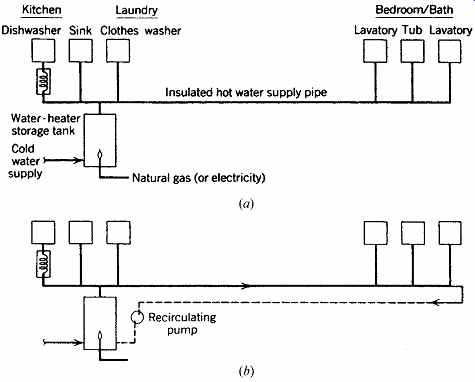
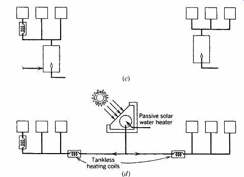
FIG. 18 Options for DHW in a larger residence. (a) Typical centralized
water-heater storage tank; water and energy are wasted in the run involved.
(b) Recirculating pump added; this saves water but requires continuous energy
to operate the pump and make up the pipe's heat losses. (c) Decentralized approach
using two water-heater storage tanks; this roughly doubles the energy lost
from storage but eliminates water and energy loss from the long pipe run. (d)
Central solar water heater/decentralized tankless heating coil combination;
it saves on water and energy but not on initial cost.
Thermosiphon hot water circulation depends upon the fact that water expands and becomes lighter when heated, as can be seen in Fig. 19a. If heat is applied to the lower loop of a glass tube, both ends of which have been inserted in an inverted bottle containing water, the water moves from A to B and rises through tube BC into the bottle. There it becomes cooled and drops through tube DA to A, is again heated, and rises in tube BC-thus completing the circulation. Because the movement depends upon the difference in weight between the two columns of water, the velocity and consequent effectiveness of the circulating system increase as both the temperature of the water and the height of the circuit increase. Hot water supply systems therefore usually consist of a heater with a storage tank, piping to carry the heated water to the farthest fixture, and a continuation of this piping to return the unused cooled water back to the heater. A constant circulation is thereby maintained, and hot water may be drawn at once from a fixture without first draining off through the faucet the cooled water that would be standing in the supply pipe if there were no recirculation. Because heat increases the corrosive action of water on metals, copper tubing or rated poly vinyl chloride (PVC) pipe is often chosen for use in hot water and hot water circulating systems.
Thermosiphon circulating systems are particularly effective in multistory buildings because of the beneficial effect of the increased circuit height on circulation.
Forced circulation of hot water is often utilized where a height advantage is unavailable.
Low, long, rambling buildings, such as some large one-story residences, schools, and factories, lack the height needed to set up good hot water circulation by gravity. Also, flow is diminished by friction in long pipe runs. For such buildings, the forced-circulation scheme shown in FIG. 20 offers one option. Three independent aquastats-devices that create an electrical signal when water temperature drops-control this system. Aquastats A, B, and C, respectively, sense the temperatures of the water in the heater, in the tank, and at the end of the circulation return main. As needed, they turn on the oil or gas burner, the tank-circulating pump, and the system-circulating pump. Fixtures remote from the tank are as close to hot water as the length of their hot water runout pipes. Water is usually available at full temperature in 5 to 10 seconds.
Trial aquastat settings in ºF could be A 180, B 160, C 120 (ºC: A 82, B 71, C 49).
(g) Variable Storage Temperature
An energy-saving computer control is available for hotels, motels, apartments, and larger commercial buildings. This device (FIG. 21) varies the supply temperatures of hot water so that the hottest water is supplied at the busiest hours. In hours of low usage, much lower supply temperatures mean that more hot water will be mixed with less cold water at showers, lavatories, and sinks. This increased hot water quantity poses no problem at off-peak hours, and the lower temperature means significant decreases in heat loss from the recirculating supply water system. A typical payback period is 1 year. The device stores a memory (adjusted weekly) of the typical daily patterns of usage and varies the supply temperature accordingly.
(h) Conventional Water Heater Selection
One of the most common appliances used in the United States is the water-heater storage tank, an energy-conserving model of which is shown in FIG. 22.
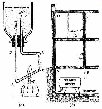
FIG. 19 (a) Principle of hot water circulation by gravity (thermosiphon).
(b) Its application to hot water service. During periods of no demand, there
is sufficient incidental cooling between C and D so that dense (less warm)
water at A forces the lighter (hot) water at B to rise for speedy availability
at each faucet.
For residences, the capacity of hot water heating/storage equipment can be taken from the values in Table 8. Note that for the familiar tank type direct water heaters (gas, electric, or oil), there is a stated relationship among storage size, rate of hourly heat input, rate of draw (demand) over 1 hour, and recovery rate. Example 2 uses Table 8 for the sizing of a residential water heater.
EXAMPLE 2
Select a natural gas water heater for a five-bedroom house with three baths. The minimum requirements of HUD-FHA are shown in Table 8: 50 gal (190 L), 47,000 Btu/h (1.38 kW), 90-gal (340 L) draw per hour, and 40 gph (151 L/h) recovery.
SOLUTION
From FIG. 22 and Table 9, a model BTH 120 is selected; it exceeds all the minimums. Estimation of the hot water demand for commercial and institutional buildings is not so simple, and design guidelines are less reliable. For larger buildings, there is a trade-off between quick recovery (high heating capacity) and storage size; big tanks have small heaters, and vice versa. Another variable is storage temperature, as discussed earlier in Section 6(a).
Small shops and very small office buildings can be treated like residences for hot water sizing. For larger buildings, the trade-off between heaters and storage tanks should be explored. To begin this process, consult Table 10, which shows the maximum hourly and daily demands and contrasts them to an average day (which should be used to estimate monthly energy consumption).
The relationship between heater size and tank size is graphed in FIG. 23. The advantage of a larger heater is its smaller tank, which consumes less space and volume, weighs less, and probably has a lower first cost. The advantage of a larger tank is that its smaller heater tends to work steadily rather than in spurts; this lower, steadier demand for energy will lead to lower utility rates in the case of electric heating and thus to money savings over the life of the system. When the fuel supply is solar energy or waste heat, a larger tank is usually best suited to the characteristics of the fuel supply.
EXAMPLE 3
(Adapted from the 1995 ASHRAE Handbook-HVAC Applications.)
A women's dormitory housing 300 students, with a cafeteria serving 300 meals in 1 hour, is to be built. Find the required hot water storage size for two conditions: (1) assuming a minimum recovery rate for both dorm and cafeteria and (2) assuming a dorm recovery rate of 2.5 gph (9.5 L/h), which is half of the maximum hourly value given in Table 10, and a cafeteria recovery rate of 1.0 gph (3.8 L/h), which is two-thirds of the maximum hourly value given in Table 10.
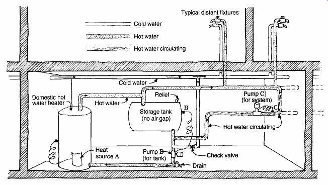
FIG. 20 Forced circulation of DHW for a long, low building. (Note that
the use of space-heating boilers for DHW may cause system inefficiencies in
warm weather.)
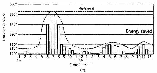
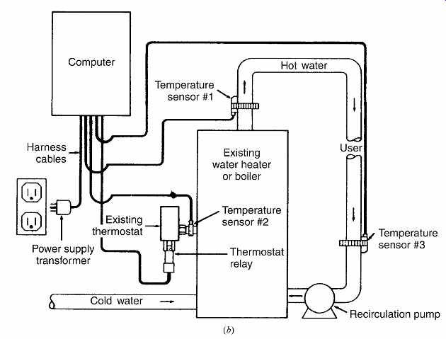
FIG. 21 Variable temperature DHW supply. (a) Energy savings are possible
when the supply temperature of hot water is varied. Heat losses from supply
pipes are greatly reduced for most of the typical day. A computer controls the
supply temperature. (b) Schematic of computer-controlled, variable-temperature
DHW system. (Courtesy of Fluidmaster, Inc., Anaheim, CA.)
SOLUTION
Minimum recovery:
From FIG. 23a, the minimum recovery rate for women's dormitories is 1.1 gph (4.2 L/h). For 300 students, 300 × 1.1 = 330 gph (300 × 4.2 = 1260 L/h) recovery At this rate, again from FIG. 23a, the minimum usable storage capacity is 12 gal/student (45 L /student). Assume that 70% of the total capacity is usable capacity. This means that after 70% of the stored hot water is withdrawn, the remaining water has been cooled (by incoming water) to an unusably low temperature. Storage size must be increased [...]
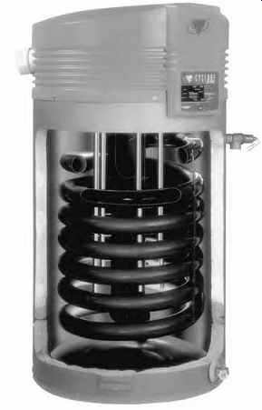
FIG. 22 "Cyclone XHE" water-heater storage tank using natural
gas (or propane). This model achieves 94% thermal efficiency with a burner
located at the top, forcing blower-driven air into a countercurrent contact
with rising fuel. A precise mix of air and fuel at the point of ignition results
in high combustion efficiency, and the swirling flame continues downward in
a submerged central combustion chamber.
The heated gas is then forced at high velocity through the spiral heat exchanger coil, with a swirling action that maximizes heat exchange with the water. (Courtesy of the A.O. Smith Water Products Company, Irving, TX.)
Table 8 HUD-FHA Minimum Water Heater Capacities, Residential PART A. I-P UNITS
Table 9 Procedure for Sizing a Residential Water-Heater Storage Tank
Table 10 Domestic Hot Water, Commercial/Institutional
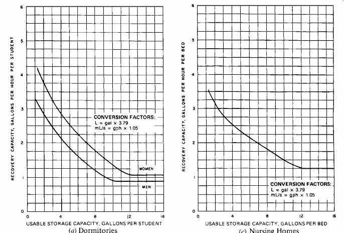
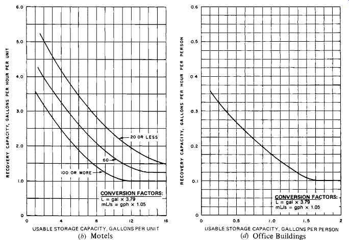

FIG. 23 Domestic hot water sizing; the trade-off between recovery (heater)
capacity and storage capacity. Usable storage capacity is usually considered
to be between 60% and 80% of the total tank capacity. For (b) Motels, and (f)
Apartments, curves are based upon the number of dwelling units. For (e) Food
service, Types A, B, see Table 10. (Reprinted by permission of the American
Society of Heating, Refrigerating and Air-Conditioning Engineers, Inc. from
the 1995 ASHRAE Handbook-HVAC Applications.)

FIG. 24 Storage tank and heater for DHW for large-demand applications.
A steam coil is submerged in the tank. Capacities from 100 to 10,000 gph (380
to 37,850 L/h), varying by length of coil, for a 140Fº (78Cº) temperature rise
(from 40 to 180ºF [4 to 82ºC]).
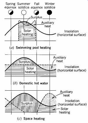
FIG. 25 Comparison of the pattern of solar energy supply (on a horizontal
surface) to various patterns of heating needs.
For these larger DHW applications, central steam is often used as a heat source. Figure 24 shows an indirect storage tank system. Such systems may cost more than tankless systems, but they are usually cheaper to operate, both because the peak prices for the instantaneous fuel demands of tankless heaters are avoided and because low-grade steam or waste high-temperature water sources can be utilized.
In any system that heats water under pres sure, safety precautions are necessary. To minimize the dangers of excessive pressure (which can damage the system) and of superheated water (which can severely injure people), most codes require pressure and temperature (P/T) relief valves to be installed on top of all water heaters. Because these valves are designed to release hot water whenever a dangerous pressure or temperature is reached, they should be attached to a length of pipe that will conduct the released water to a drain.
(i) Solar Water Heating
Solar energy is most attractive to a designer when it will do most of its work during the time that it is most available. On a seasonal basis (FIG. 25), solar energy is especially attractive for outdoor swimming pool heating, as it will be used only in sunny, warm months. Throughout the United States, solar energy can easily meet most of the summertime demand for DHW as well. In the northern part of the country, a much smaller solar contribution can be expected in winter. An especially difficult problem is the winter space-heat mismatch between greatest need and least solar energy supply. For both solar DHW and space-heating systems, winter brings the added complication of the need to protect against freezing.
complications of mechanical breakdown, increased maintenance, and the cost of the energy needed to run the pump. Active DHW systems are widespread in North America; see Figs. 27 and 28 for typical systems.
Direct systems utilize only one fluid: the water to be heated for use in the building is circulated through the solar collector. Such a system has the advantages of simplicity and efficiency, as it does not require a separate fluid loop and the attendant piping complications and inefficiencies of heat exchange.
Indirect systems use a closed loop containing a fluid that circulates through the collector and storage tank. The fluid is not mixed with the DHW itself; rather, heat is passed from one fluid to the other through a heat exchanger. One advantage of this system is that it allows nonfreezing solutions to be used in the collector loop. It also allows collectors to be operated at low pressure rather than at the high pressures typical of urban public water systems. The choice of fluid is determined by Again, there are many ways in which solar energy can be used to heat water. Solar water heating systems are usually classified by the means of fluid circulation (passive or active), the means by which heat from the collector piping is transferred to the DHW itself (direct, indirect, or closed-loop), and the means of protection against freezing.
Passive systems rely upon gravity for circulation, as explained in Section 6(f). Hence, the storage tank usually must be placed above the collector (FIG. 26) and the number of bends in the system supply and return piping minimized to reduce friction. Heavy storage tanks located high in a building can cause structural problems.
The advantages of this passive approach include lower cost of components, high mechanical reliability (no pump, etc.), and low operational costs.
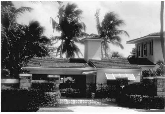
FIG. 26 Solar water heaters are widely used. This house in Miami, Florida,
incorporates a storage tank above the collector, which is enclosed in the chimney-like
form. This permits passive (thermosiphon) circulation without a pump. (Photo
by M. Steven Baker.)
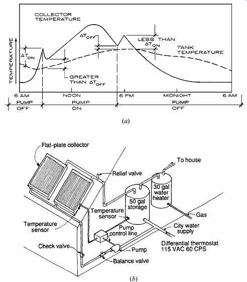
FIG. 27 Active solar water heating utilizes differential controllers (a)
that compare the collector temperature to that of the storage tank. (b) Typical
DHW system with separate solar and conventional heater tanks. (The alternative
of only one storage tank produces less standby heat loss, but may reduce solar
collection by feeding the collector with gas-heated water.)
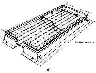
FIG. 28 (a) Cutaway section of a typical active solar collector.
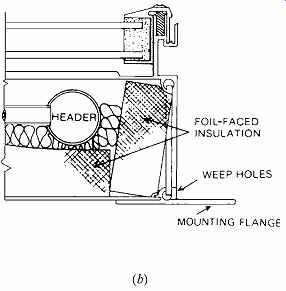
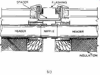
(b) Cross section at the header. (c) Method of connecting manifolds of adjacent
solar collectors.
Active systems use pumps to force the fluid into the collector. Although this setup allows the collector and storage to be located anywhere that is convenient for the designer, it introduces the its freezing and boiling points, its specific heat, and its level of toxicity.
As Table 11 shows, these design elements (passive and active, direct and indirect) are combined in a number of typical solar DHW systems.
Brief descriptions of some of the more common systems follow.
1. Batch systems. In these, the simplest of all such systems, a black-painted storage tank is exposed to the sun within a glazed collector box (FIG. 29). The price of simplicity is the inefficiency of exposing a tank of hot water to the cold nighttime conditions of the collector. Movable insulation, however inconvenient, can be used to reduce this problem. These heaters are also referred to as breadbox water heaters and integral passive solar water heaters. The batch system was used at the Antelope Valley California Poppy Reserve, as shown in FIG. 30. Because of their simplicity, they are favored by do-it-yourself builders, especially in mild winter climates.
A more recent batch collector design utilizes eight copper tubes in a well-insulated, double glazed (glass out, Teflon in) frame. The water flows in series, allowing the colder replacement water to enter at the bottom of the collector, with the hottest water at the top, ready for use.
Insulation between the tubes helps maintain this temperature difference. Collectors are available in storage sizes of approximately 30, 35, 40, and 50 gal, weighing when filled 425 to 664 lb (114, 133, 152, and 190 L, weighing 193 to 301 kg).
2. Thermosiphon systems. The sun acts as both the pump and the heat source for these systems (FIG. 31). With no moving parts, maintenance needs are low. The collector, however, must be lower than the tank, and piping must be kept as simple as possible. Because the coldest water remains in the lower collector at night, the hot water in the upper tank is not threatened with undue heat loss. However, freezing conditions pose a severe threat to the collector. Accordingly, indirect (closed-loop) systems containing a nonfreezing fluid are frequently used; phase-change systems are a promising cold-winter option for this type of passive system.
3. Closed-loop, freeze-resistant systems. In addition to being used in thermosiphoning arrangements, these systems are commonly used in active systems (FIG. 32). A small pump circulates non freezing fluid to the collector when there is sufficient sun. This process is governed by a differential controller. Alternatively, a PV-(photovoltaic) driven circulation pump can be used; when there is sufficient solar energy to activate the pump, there should be enough to also heat water in the collector.
The price of this freeze protection is the inefficiency of the heat exchanger, used between the collector fluid and the potable hot water. Some codes require a double-wall heat exchanger between any toxic nonfreezing fluid and the potable water, which further reduces efficiency.
4. Drain-back systems. Although these systems (FIG. 33a) use water as the fluid pumped from tank to collector, this water is not the potable hot water itself. Instead, the potable water passes through a heat exchanger in the solar storage tank. With the potable water kept out of the collector, the solar collector can operate at lower water pressure. This arrangement, however, requires a large heat exchanger, with attendant inefficiency.
It also requires care in the design and installation of piping between the collector and tank so that the collector will drain thoroughly. When the controller senses that no solar energy can be gathered, it cuts off the pump, and water drains back into the tank. Therefore, the collector will be filled with air, not water, during all nighttime and cloudy-cold daytime hours. Corrosion inhibitors should be added to the collector/tank's water because the piping is frequently exposed to air.
Table 11 Solar Domestic Hot Water Systems
---------
Type Main Features Advantages Disadvantages Batch system Batch tank inside collector box.
Potable water within collector/tank.
No external power.
Few components.
Collector/tank at any location.
Seasonal; dependent on freezing locations.
Heat loss at night from storage.
Thermosiphon system
Flat-plate liquid collectors.
Normally open loop but no pump or external power passive (DHW system).
Storage tank higher than collector.
No external power.
Few components.
High performance.
Seasonal; dependent on freezing locations (if water is collector fluid).
Needs structural support for high storage tank.
Geyser pumping system Flat-plate liquid collectors.
Methanol-water solution passively pumped by solar heat to a heat exchanger below.
No freezing damage.
No mechanical or electric parts.
No liquid service.
Temporarily stops operation at subzero temperatures, as solution freezes to a slush.
Closed-loop freeze resistant system
Flat-plate liquid collectors.
Closed loop of piping from collectors to storage tank.
Uses external energy (circulator and differential controller).
Uses nonfreezing collector fluid.
Pressurized stone-lined storage tank.
Can be used in coldest climates.
More and better-established competition.
Circulator; small consumption of external energy.
High performance.
Liquid; service/maintenance required.
More components required.
Drain-back system
Flat-plate liquid collectors.
Water is collector fluid (open loop).
Potable water circulates through the heat exchanger in the storage tank (not through the collectors).
Large heat exchanger.
Pitched headers.
Can be used in the coldest climates.
No antifreeze used.
Most simple of active flat plate systems (no valves).
Larger pump; larger consumption of external energy.
System must drain thoroughly.
Use of corrosion inhibitor recommended.
Drain-down system
Flat-plate liquid collectors.
Potable water circulated through collectors.
Line pressure feeds collectors (open loop).
Has automatic drainage valves.
Pitched headers.
No heat exchanger or extra storage tank needed.
High performance.
In some instances a larger pump; larger consumption of external energy.
System must drain thoroughly.
No corrosion inhibitor possible.
Freeze danger with valve failure.
Air-to-liquid system
Flat-plate air collectors.
Air-to-water heat exchanger.
Ductwork and blower.
Pipes and circulator.
Larger collector area than liquid system.
Won't freeze (dependent on exchanger location).
Air leaks won't cause damage.
Integrates well with space heating.
Hard to detect leaks.
More space required for ducts.
Blower and circulator required.
More carpentry involved.
Less efficient than other systems.
Phase-change system
Flat-plate liquid collectors.
Freon 114 or R12.
b Storage tank higher than collectors (passive type).
Closed-loop refrigerant-grade piping from collectors to storage tank (passive type) or to condenser (subambient type).
No external power (passive type).
Can be mounted at any location (subambient type).
Very hard to detect leaks.
Special equipment to install.
More components required (subambient type).
----------
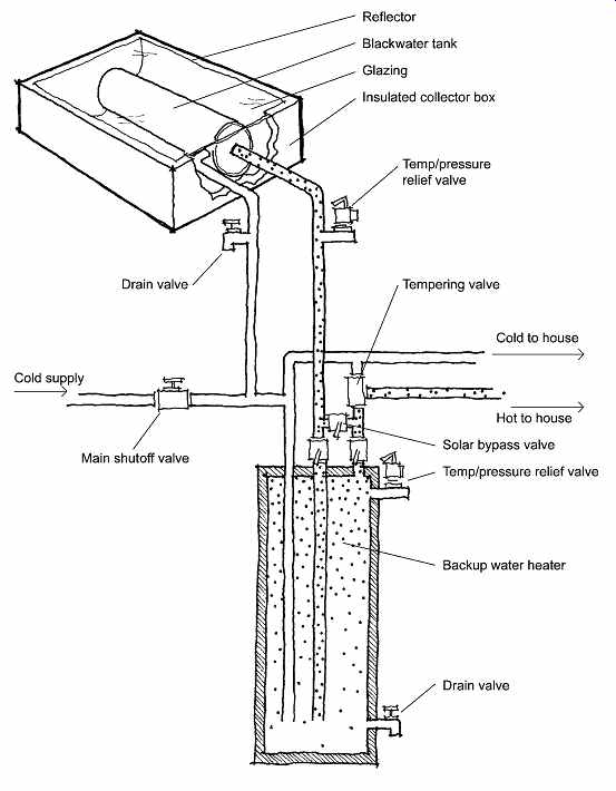
FIG. 29 Batch solar water-heating system. (Drawn by Dain Carlson; © 2004
Alison Kwok; all rights reserved.)
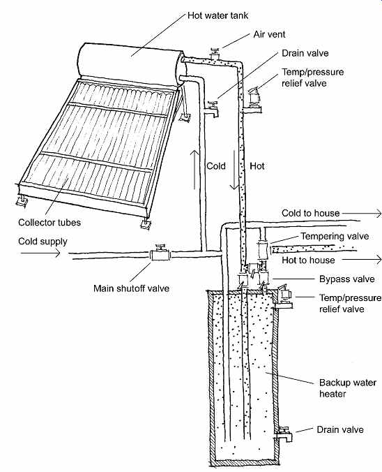
FIG. 31 Thermosiphon solar water-heating system. (Drawn by Dain Carlson;
© 2004 Alison Kwok; all rights reserved.)
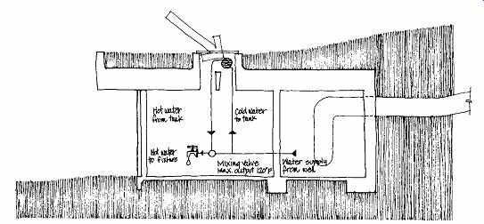
FIG. 30 A batch solar water heater supplies the hot water for the Antelope
Valley California Poppy Reserve. (Courtesy of the Colyer/Freeman Group, Architects,
San Francisco.)
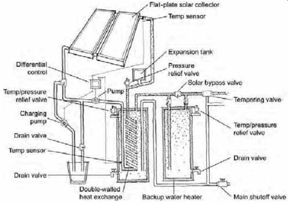
FIG. 32
Closed-loop, freeze-resistant solar water heating system.
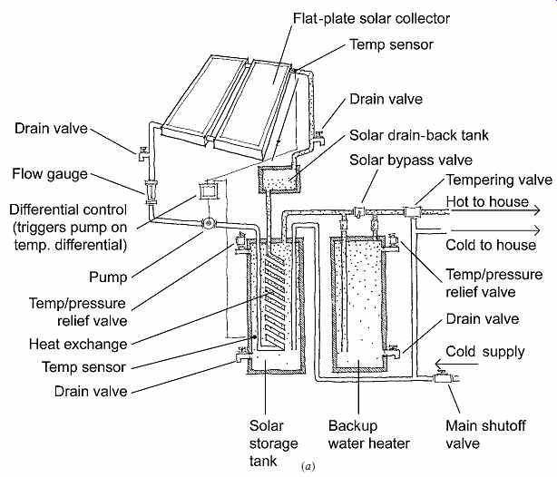
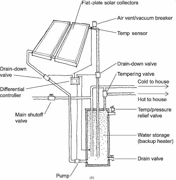
FIG. 33 Comparison of (a) a drain-back solar water-heating system with
(b) a drain-down system. The drain-back system's performance can be increased
by the addition of a check valve that allows the colder water at the bottom
of the storage tank to circulate into the heat exchanger. The drain-down system
is best used in mild-winter climates with infrequent freezing temperatures,
since the water in the collector is dumped with each freezing threat. (Drawings
by Dain Carlson; © 2004 Alison Kwok; all rights reserved.) (a)
5. Drain-down systems. These are the only active systems that do not utilize heat exchangers (FIG. 33b); DHW is circulated directly through the collector. Both higher pressure and higher efficiency result. In this system, the collector is usually filled with water that moves only when a differential controller activates the pump. When ever the outside temperature drops near freezing, the controller activates solenoid valves and the water in the collector is drained down (dumped). In cold-winter areas, this process can result in several gallons of water wasted per winter day.
Although the lack of a heat exchanger is attractive from the standpoint of cost savings and thermal efficiency, the set of electrically controlled solenoid valves is not foolproof. When malfunctions occur in pressurized systems, the loss of water can be enormous, and there is great potential for water damage to the building.
6. Air-to-liquid systems. These systems use air collectors and rock storage beds; a heat exchanger transfers heat from the collector-heated air to the hot water. Much lower efficiencies result, and the ductwork is much more space-consuming than are pipes for water collectors. Leaks in air collectors or storage beds are very difficult to detect. However, air collectors are not damaged by freezing.
7. Phase-change systems. In any of the afore mentioned systems in which potable water is kept
out of the collector, the fluid within the collector not only can be freeze-resisting, but also can take advantage of latent heat (the considerable amount of heat stored when fluid vaporizes and released when a fluid condenses). The primary disadvantages of a phase-change system (FIG. 34) are the high first cost, the difficulty in detecting leaks, and the resulting threat of chlorofluorocarbon or hydrochlorofluorocarbon refrigerant fluids to the environment.
Passive approaches to phase-change materials were outlined in the discussion of thermosiphoning systems. Subambient approaches utilize a heat pump and can glean heat even from cold-cloudy ("sub ambient") conditions. They thus represent a form of solar-assisted heat pump, closely related to those discussed in Section 6(j).
The sizing of solar water heaters usually begins with simple design guidelines. For batch heaters, such a sizing guideline (FIG. 35) is:
0.45 to 0.65 ft 2 glazing per gallon of water stored (0.011 to 0.016 m2 per liter of water stored) For the flat-plate solar collectors used in all the solar DHW systems listed in this section, the sizing guidelines are: 12 to 25 ft 2 collector/person (residential) (1.1 to 2.3 m2/person) Optimum tilt (up from the horizontal) equal to latitude (or less) 1 to 1.5 gal of storage per square foot of collector area (41 to 61 L per square meter of collector area) This collector-sizing guideline is for residential hot water usage, including cooking and bathing. For warmer climates with ample insolation, use the lower figure; this will supply about half of the hot water on an annual average basis. (For nonresidential DHW, adjust the sizing guideline by comparing the gallons of hot water per person per day used in residences to those used in the nonresidential function under design.) A more detailed sizing procedure would consider the collector's expected heat contribution for some typical months. Such a procedure requires both climate data and assumptions about water temperatures and other values. As a result, detailed answers are best obtained from computer programs, such as those listed in Appendix M. For those interested in something more than sizing guidelines but less than computer programs, consider the following approach to collector sizing (adapted from Brown, Reynolds, and Ubbelohde, Inside Out: Design Procedures for Passive Environ mental Technologies, © 1982 by John Wiley & Sons).
STEP 1. Select the collector tilt angle. This can be done by consulting Appendix C, Tables C.11 to C.14 for I-P (C.15 to C18 for SI), which present clear-day insolation values for various tilt angles. Table C.19 for I-P (C.20 for SI) presents average insolation values on horizontal surfaces, which should also be checked. The tilt angle selected should be close to the optimum angle for the best month for total insolation.
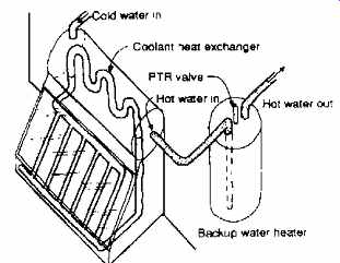
FIG. 34 In a phase-change system, small heat exchangers can be built into
the tops of thermosiphoning collectors; DHW is drained down when the threat
of freezing arises. (Adapted by permission from Solar Age, November 1983.)
STEP 2. Check the collector efficiency. This should be done at least twice: for the best insolation month and for the worst month. This step requires the following data:
Hourly insolation on tilted surface (Appendix C, Tables C.11 to C.14 for I-P [C.15 to C.18 for SI]) Outdoor average temperature (Appendix C, Table C.19 for I-P [C.20 for SI]) The hourly insolation values on tilted surfaces in Tables C.11 to C.14 (and C.15 to C.18) are for clear days. For most locations, this should be adjusted for average conditions, which are shown for vertical (south) and horizontal surfaces in Table C.19 (and C.20). Because for most of North America the optimum yearly DHW tilt angle will be closer to horizontal than to vertical, a simple correction to insolation must be made:
Hourly average day insolation on tilted surface.
This step also requires assumptions about the input temperature of the water supplied to the collector (Ti ). In summer, this can be quite high-even higher than the thermostat setpoint temperature of the hot water tank. In winter, it is likely to be lower, by perhaps 10 to 20Fº (5.5 to 11Cº), than the thermostat setpoint temperature.
Finally, this step requires a choice of collector type so that efficiency can be determined. Figure 36 shows the efficiency curves for a variety of solar collectors.
Note that the simplest of all, the unglazed flat black collectors, have the highest efficiency of all collectors at combinations of very low Ti - Ta and very high Io. These conditions are typical of summer days, on which the water needs to be heated only a few degrees. This corresponds to swimming pool applications and is one reason such collectors are so popular for that purpose; low cost is another reason.
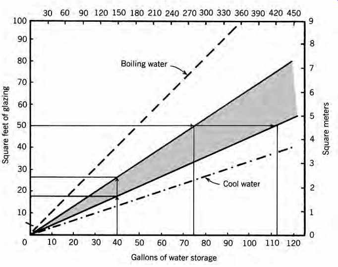
FIG. 35 Design guideline for the sizing of batch solar water heaters. In
this example, a 40-gal (150-L) storage tank should be contained within a collector
that has between 18 and 27 ft 2 (1.7 and 2.5 m2) of south-facing glazing, or
a 50-ft 2 (4.7-m2) collector box should contain a tank of between 75 and 113
gal (285 and 430 L). (Adapted from Daniel K. Reif, Passive Solar Water Heaters;
copyright © 1983 by Brick House Publishing Company, Inc. Reprinted by permission.)
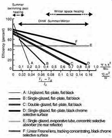
FIG. 36 Collector efficiencies depend upon insolation (Io ), water temperature
entering the collector (Ti), and ambient (air) temperature (Ta). (Based on
the U.S. Dept. of Housing and Urban Development's Intermediate Minimum Property
Standards Supplement, 1977.)
For the opposite conditions-those of winter space heating-more elaborate collectors are appropriate. Evacuated-tube collectors have the advantage of nearly eliminating collector heat loss by convection. Fresnel lens and/or tracking-concentrating collectors increase the incoming solar energy per unit area, whereas heat loss increases only slightly (due to higher delta t). Both of these approaches are expensive, and tracking collectors require added maintenance for the tracking mechanism. Selective surfaces represent a simple, relatively cheap improvement over flat black collectors (compare D to B); they absorb solar energy just as well but emit radiant energy at a vastly lower rate, thus cutting collector heat loss by radiation.
STEP 3. Approximate system efficiency. Once the hot water leaves a collector, it must be led back to storage. In indirect systems, it must go through a heat exchanger. The tank will lose some heat; heat losses also occur as the cooled water is led back to the collector. Another "loss" to be considered is non-collection time. Estimates of collector performance are based on total daily insolation, yet the first few and last few hours of daylight generally will not bring enough insolation to warm the collector.
Therefore, some reduction should be made in daily insolation totals when performance is estimated.
All these factors can be accounted for by assuming a lower system efficiency. A perhaps optimistic assumption is that system efficiency = (0.8) × (collector efficiency).
STEP 4. Determine the total heat needed for DHW. Estimates of the quantity of hot water needed were made in Section 6(h). Once the total gallons (or liters) per day are known and the desired storage temperature determined, the heat needed for the daily supply of DHW is easy to calculate. In I-P units:
Q = 8.33 (gpd) (ts - tg) where
Q = daily heat need, Btu
8.33 = weight of water, pounds per gallon × Btu/lb ºF
ts = storage temperature, ºF (see Table 7)
tg = groundwater temperature, ºF (see FIG. 8.56, well-water temperatures) In SI units:
Q = 1.16 (L /d) (ts - tg) where
Q = daily heat need, Wh
1.16 = the SI equivalent of the 8.33 factor
ts = storage temperature, ºC
tg = groundwater temperature, ºC
STEP 5. Determine the desired percentage solar contribution to DHW. There are several approaches to this problem. One common strategy is to have solar provide 100% of the hot water needs in the best insolation month. A closely related strategy is to choose the yearly percentage of solar heat desired and then provide that percentage in the average month (such as March). Whatever strategy is chosen, a month and its percentage of solar heat must be identified.
STEP 6. Size the collector. This is done by combining the preceding steps as follows:
collector area =
× daily heat need percent solar desired daily insolation system efficiency ×
This may be done for several months as a check on optimum collector size.
EXAMPLE 4 Determine the approximate size of solar collectors needed to serve the women's dormitory
[...]
Swimming pool heating is an especially attractive application for solar energy. A common design guideline for collector sizing is collector area = 0.5 pool surface area For summer ambient temperature operations, un -
glazed collectors are both the best-performing and the least expensive, as explained for FIG. 36.
Another important consideration is a pool cover, which will not only conserve the pool's heat but also reduce water lost by evaporation. On very hot dry days, water losses can reach 100 gpd from a 20 × 40-ft pool (380 L/day from a 6 × 12-m pool).
(j) Heat Pump Water Heaters
The heat pump's use of the compressive refrigeration cycle was explained in Section 9. Air-water heat pumps are also used for DHW, as shown in FIG. 37. Because these devices remove heat from the air, they are usually installed either in normally overheated spaces (such as restaurant kitchens) or in unheated spaces such as garages or basements. (They can also remove heat from exhaust air, as explained in Section 5.) The spaces that contain these units will be cooled and dehumidified. Heat pumps require only a little more space than the simple hot-water storage tanks they serve. Some noise is created by the compressor and the fan that moves air across the evaporator.
Heat rejected from any refrigeration unit can be used for heating water via the heat pump. Applications include ice-making machines, refrigerated display units in grocery stores, walk-in freezers, and many others. Whenever constant refrigeration loads are present, there is an opportunity to utilize waste heat.
Graywater provides another opportunity for using a heat pump. Where filtered graywater is collected for recycling on site (as for irrigation systems), a water-water heat pump can heat a DHW storage tank as it lowers the graywater tank temperature.
See Section 22 for graywater system design.
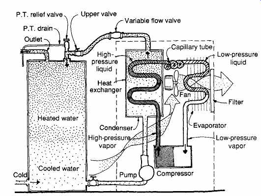
FIG. 37 Heat pump (air-water) used for heating DHW. (Adapted by permission
from Specifying Engineer, October 1983. © 1983 by Cahners Publishing Co.)