AMAZON multi-meters discounts AMAZON oscilloscope discounts
(cont. from part 1)
5. WATER SOURCES
This section focuses on the equipment used to cap ture and store groundwater from wells. Other water sources are less often used for smaller systems, either because they require much more extensive treatment (surface water from lakes or rivers) or because they provide water intermittently (cisterns). A multistage treatment (flocculation, sedimentation, etc.) may be inappropriate for small water systems that receive only occasional maintenance. Cisterns were discussed in Section 20. Another increasingly important source of city water, the treated effluent of sewage treatment plants, is discussed in Section 22.
(a) Wells
Farms and remote housing developments usually have private water systems. In rural and suburban areas where the progress of building is faster than the development of municipal water supplies, private sources may also be sought. Driven or drilled wells are preferable; water from these sources usually has at least the advantages of purity, coolness, and freedom from turbidity, odor, and unpleasant taste-any of which may be encountered in addition to either acidity or hardness.
Bored wells, which are dug with earth augers, are usually less than 100 ft (30 m) deep. They are used when the earth to be bored through is boulder free and will not cave in. The diameter range is 2 to 30 in. (50 to 760 mm). The bored well is then cased with metal, vitrified tile, or concrete.
Driven wells are the simplest and usually the least expensive type. A steel drive-well point is fitted on the end of pipe sections and driven into the earth.
The drive point is usually 1¼ to 2 in. (32 to 50 mm) in diameter. The materials and design of drive-well points vary according to the expected characteristics of the earth in which the well is driven. First, a pilot hole is bored (frequently with a simple hand auger), and the drive-well point and pipe sections are lowered into it. Then the well is driven to a point well below the water table.
Jetted wells require a source of water and a pres sure pump. A washing well point is supplied with water under pressure; this loosens the earth and allows the point and pipe to penetrate.
Drilled wells require more elaborate equipment of several types, depending upon the geology of the site. The percussion (or cable-tool) method involves the raising and dropping of a heavy drill bit and stem. Having thus been pulverized, the earth being drilled is mixed with water to form a slurry, which is periodically removed. As drilling proceeds, a casing is also lowered (except when drilling through rock).
Rotary drilling methods (either hydraulic or pneumatic) utilize a cutting bit at the lower end of a drill pipe; a drilling fluid (or pressurized air) is constantly pumped to the cutting bit to aid in the removal of particles of earth, which are then brought to the surface. After the drill pipe is with drawn, a casing is lowered into position.
Another method is the down-the-hole pneumatic (air) hammer method, which combines the percussion effect with a rotary drill bit.
Local well drillers, who usually use the method most suited to the prevailing geology of a region, can offer useful advice about well construction methods.
When clients plan to build in a remote location, the architect and engineer should advise them about water problems. Quality-corrective measures can always be taken and pumping equipment purchased, but the amount of water that can be obtained from the ground, and the depth and cost of wells, are important considerations. There are some problem areas where wells several hundred feet in depth will yield as little as 5 gpm (0.3 L/s) or nothing. The cost of drilling a number of exploratory wells may be excessive. Unfortunately, when such difficulties occur, there is often no easy solution. Conferences with neighboring owners, state and federal geologists, and local well drillers can all be helpful.
A low-yield well can be combined with storage tanks so that a pump can run all night, slowly filling tanks to meet the next day's demands.
(b) Pumps
The Hydraulic Institute, a nonprofit trade association of pump manufacturers, has several recommendations for reducing the amount of electricity consumed by pumps. Some of these apply to small water supply systems.
1. Design systems with lower capacity and total head requirements. (Using larger pipe sizes and minimizing the elevation of tanks are examples.)
2. Avoid excessive capacity. It is typically less expensive to add pumping capacity later on if needs increase. Operating a smaller pump closer to its capacity saves energy compared to a larger pump operating well under its capacity.
3. Select the most efficient pump type and size, even if its first cost is greater; life-cycle costs are likely to be lower.
4. Use two (or more) smaller pumps instead of one large one so that excess pump capacity can be turned off.
5. Maintain pumps and system components in virtually new condition to avoid efficiency loss.
Three common types of pumps used in well water supply are the positive displacement, the centrifugal, and the jet pump.
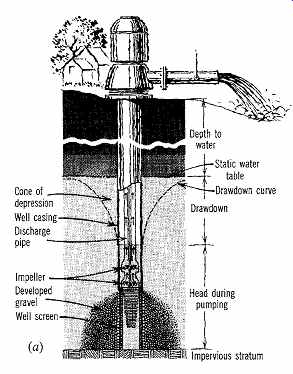
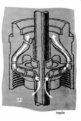
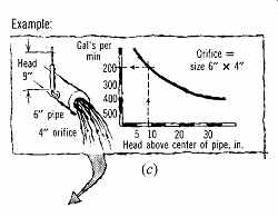
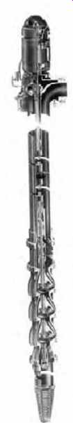
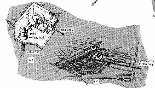
FIG. 9 (a) A turbine well-pump. (b) Its operation. (c) Measurement of its
capacity. (d) A Jacuzzi multistage lineshaft turbine well pump. (Jacuzzi Bros.,
Inc.) (e, f) Its use in supplying a small community with groundwater. Capacities
of turbine pumps range from 50 to 16,000 gpm (3 to 1010 L/s). (By permission
of Progressive Architecture.)
Positive Displacement Pumps. There are two principal types of positive displacement pumps. In a reciprocating pump, a plunger moves back and forth within a cylinder equipped with check valves. The cylinder is best located near or below the ground water level. Water enters the cylinder through an initial check valve (which allows flow in only one direction). As the plunger moves toward this check valve, the water is forced through the second check valve, located within the plunger itself. Then, as the piston returns to its original position, the water is forced upward toward the surface.
A rotary pump has a helical or spiral rotor-a turning vertical shaft within a rubber sleeve. As the rotor turns, it traps water between it and the sleeve, thus forcing the water to the upper end of the rotor.
Centrifugal Pumps. This type of pump contains an impeller mounted on a rotating shaft. The rotating impeller increases the water's velocity while forcing the water into a casing, thus converting the water's velocity into higher pressure. Each impeller and casing is called a stage; many stages can be combined in a multistage pump. The number of stages depends upon the pressure needed to operate the water supply system, as well as the height to which the water must be raised. The most common centrifugal pumps are those used in deep wells.
The turbine pump has a vertical turbine located below groundwater level and a driving motor located higher up, usually over the well casing at grade. A long shaft is thus required between the motor and the turbine. Substantial head clearances for this shaft's removal may be required.
Figure 9 shows a turbine pump installation for a small community on Long Island, New York.
The water is taken from the ground by multistage turbine pumps at depths of several hundred feet (a hundred or so meters). It is delivered to submerged hydropneumatic tanks at a pressure of about 80 psi (about 550 kPa). As water is required in the houses, the air under pressure in the upper part of the tanks forces water through the mains.
Submersible pumps are designed so that the motor can be submerged along with the turbine (FIG. 10). The lengthy pump shaft is thus eliminated.
Jet (or Ejector) Pumps. In a jet pump, a venturi tube is added to the centrifugal pump. A portion of the water that is discharged from a centrifugal pump at the wellhead is forced down to a nozzle and the venturi tube (FIG. 11). The lower pres sure within the venturi tube induces well water to flow in, and the velocity of the water from the nozzle pushes it up toward the centrifugal pump, which can then lift it more easily by suction.
Pump Selection. Pump variations and characteristics are summarized in Table 4. The type of pump selected depends upon many factors, including the rate of yield of a well, the daily flow (and maximum instantaneous flow rate) needed by the users, the size of the storage or pressure tank used, and the total operating pressure against which the pump works (including the height to which water must be raised within the well). First cost, maintenance, and reliability are also factors, as is the energy used by the pump. In cold climates, a pump and water supply system must be protected from freezing.
Of these factors, the two critical selection determinants are the flow rate (volume per minute or per hour to be delivered) and the total pressure (or head). The flow rate depends upon the number of fixtures to be served (FIG. 12). The total pressure (Fig.
13) includes the suction lift, static head, and friction loss plus the pressure head. This relation ship will be explained in detail in Section 11.
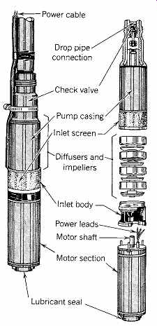
FIG. 10 Submersible pump (centrifugal type) in exploded view. (From the
U.S. EPA's Manual of Individual Water Supply Systems, 1975.)
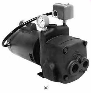
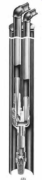
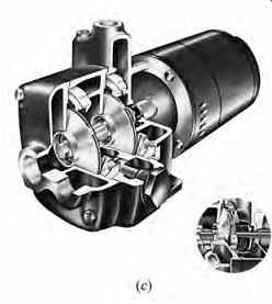
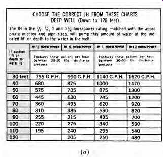
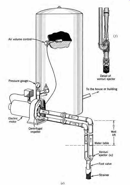
FIG. 11 Details of a deep-well jet pump. (a) Photograph of a multistage
jet pump housing and equipment. At the top is the on/off electrical switch
activated by pressure settings. It controls the direct-connected electric motor
to the left. Impellers are enclosed in the pump housing at the right. Circulating
connections to and from the jet can be seen to the right, the pump discharge
at the top. The pump can be set to operate up to 100 psi (690 kPa). (b) Well
casing and circulating lines. Jet element can be seen at the bottom of the
left-hand (larger) pipe. (c) Cutaway section of the pump. (d) Pumping capacity
in gph under various conditions and discharge pressure ranges of 20 to 50 psi
and 30 to 60 psi. (Jacuzzi Bros., Inc.) (e) Jet-type (also known as venturi
or ejector) deep-well pump and storage tank for a house or small building (for
well lifts greater than 25 ft [7.6 m]). Reduced pres sure at (f), the jet nozzle,
induces the flow of groundwater into the circulated flow.
Table 4 Pumps for Water Supply
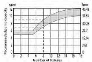
FIG. 12 The relationship between the recommended flow rate capacity of
a pump and the number of domestic plumbing fixtures it supplies. For details,
see Section 9(a). (Redrawn with SI units by Nathan Majeski; from the U.S.
EPA's Manual of Individual Water Supply Systems, 1976.)
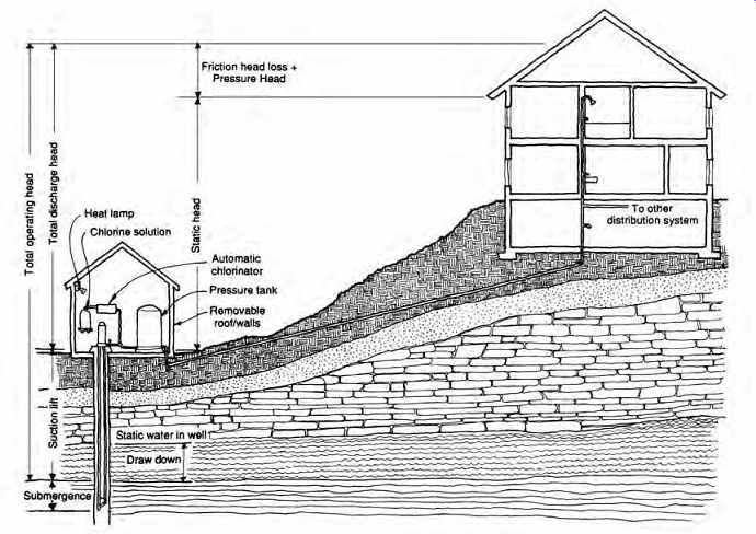
FIG. 13 The components of the total operating pressure (or head), a critical
determinant of pump size. For details, see Section 9(a). The pump house
is usually a separate structure with water treatment and storage components.
(From the U.S. EPA's Manual of Individual Water Supply Systems, 1975.)
(c) Pressure Tanks
Serving also for water storage, these tanks are frequently used both to maintain a constant pres sure on a pump-supplied water system and to allow for temporary peaks in water supply rates that exceed the capacity of the pump. (Elevated tanks offer one alternative to pressure tanks, cisterns another-although the latter usually are not located high enough to provide pressure to the supply system.) Pressure tanks are often housed in outbuildings, along with the pump and any water treatment equipment (FIG. 13). The temperature of the out-building must be kept above freezing, and its roof or walls should be removable to allow for replacement of parts over time. One type of pressure-storage tank is shown in FIG. 14.
The capacity of pressure tanks usually is small in comparison to the daily total water consumption; they provide short-term responses to peak flow demands. As a general rule, the pressure tank should be sized to deliver about 10 times the pump's capacity in gpm (L/m). For a typical residence, allow 10 to 15 gal (38 to 57 L) tank capacity per person served.
The ranges of allowable pressures are discussed in Section 9. An alternative tank-sizing procedure is shown in Table 5.
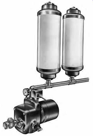
FIG. 14 Small pressure-storage tanks are installed primarily to keep a
water supply system at constant pressure. These Hydrocel models are small (8½
in. in diameter, 27 in. long [216 mm in diameter, 686 mm long]), so they can
be installed almost anywhere along the supply system. (Courtesy of Jacuzzi
Bros., Inc.)
EXAMPLE 1
An office building in a remote location has a water supply system served by a pump and well. The peak demand is 50 gpm (3.15 L/s).
Table 5 Calculations to Establish Capacity of Water Storage Tanks at Kinloch (FIG. 15)
The fixtures will operate at a minimum of 50 psi (345 kPa); a maximum of 70 psi (483 kPa) should not be exceeded. Therefore,
Qm = 15 min × 50 gpm = 750 gal (15 min × 60 s/min × 3.15 L/s = 2835 L) and ...
The capacity of elevated tanks usually is equal to at least 2 days of average water usage.
For firefighting or other special requirements, the capacity may have to be even greater.
A summary of the quality, treatment, and supply issues raised thus far is provided in the example of a rural estate shown in FIG. 15 and Table 5. On this large estate, water was required for an estimated demand of 30,000 gpd (113,560 Lpd). This was for domestic use only; irrigation was served by a separate installation pumping from a lake. Wells were dug for the domestic sup ply. It was quickly evident that despite the great depths of the wells drilled, the available flow would be small. Four wells yielded a total rate of only 25 gpm (1.6 L/s).

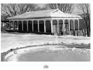
FIG. 15 (a) Schematic diagram of the water control and distribution center
for the Kinloch Estate. (Bentel & Bentel, Architects, FAIA.) The plant
is located on a hillside below the bathing and dressing pavilion. (b) One of
two pavilions adjacent to the swimming pool that serves residents and guests
at Kinloch. Below this pavilion is the control center. Exterior tubing to and
from the control center is all below grade.
Calculations for the amount of water to be stored to supplement this meager supply are shown in Table 5. The table shows that during the 14 daytime hours under conditions of peak demand, the well pumps would run continuously. Concurrently, an additional 9000 gal (34,065 L) would be drawn from the tanks. At night, the well pumps would run for 6 hours to restore the 9000 gal (34,065 L) drawn from the tanks during the day.
The operation of the system is illustrated in the diagram and notes of FIG. 15a. The pres sure of 75 psi (517 kPa) in the hydropneumatic tank is sufficient to raise the water to the greatest height in the distribution system, overcome friction in the piping, and leave a residual pressure available at each fixture of about 10 to 15 psi (69 to 103 kPa). Excessive pressure can always be moderated by a valve in the branch supply of the fixture.
Pressure in this tank is ensured by the air compressor, activated by a pressure switch. A float switch starts the centrifugal pump to deliver water from the storage tanks as needed. The storage tanks, piped together and acting as a single reservoir, are fed by the four wells. The wells operate in unison, singly, or in groups, depending upon the level in the storage tanks. If the level drops rapidly, all well pumps can run. Although they are arranged to operate all day when needed, during periods of minimum demand only one or two may be called upon. Each has its own power supply, but controls emanate from panel N.
Swimming pools should be supplied with pure, potable water. Biological tests showed that this well water was safe. Thus, the fill line to the swimming pool is connected from this system rather than from the lake water supply used for irrigation. Because swimming pool water is separately recirculated and provided with its own purification treatment at a location adjacent to the pool, the supply line for makeup water to the pool would have infrequent and off-hour use. Water for domestic use in the buildings is passed through one of three ion exchangers to provide softening and to make the water more suitable for washing, bathing, and cooking. Periodically, the calcium precipitate can be flushed out and the tanks regenerated by sodium chloride.