AMAZON multi-meters discounts AMAZON oscilloscope discounts
1. Modern pumps for hydrocarbon-based and synthetic heat-transfer oils
Introduction
As soon as the temperature in a heat-transfer system becomes too high for water, a plant operator must choose between hydrocarbon-based or synthetic oils as the heat-transfer liquid.
This usually happens once process temperatures in excess of 200 degrees become necessary. Until recently, hydrocarbon-based heat-transfer oils were often the first choice simply because they cost less. But synthetic oils are now beginning to assume a more prominent role.
The advantages of synthetic oils are appreciated over the long term. Synthetic oils pay for themselves in just a few years, with the exact time depending on the application, the system, and of course the temperature. This is especially important since as temperature rises, a greater amount of decomposition products with varying boiling point properties will form in the oil. These contaminants influence the properties of the heat-transfer liquid itself usually in a negative way. The consequences extend beyond just having to replace the thermal transfer fill more often. More serious are deposits that form in the system, since these are difficult or impossible to remove. An operator's choice of oil will determine whether new oil is needed every year, every three years, or longer. In fact, when modern synthetic oils are used, systems with process temperatures up to about 300 degrees can stay in service for their entire service life with one fill. So clearly, synthetic oils are worth the significantly higher price.
Furthermore, once process temperatures rise above 300 degrees only high quality synthetic oils will be appropriate. At these temperatures, service life will be dependant on the chemistry of the thermal transfer liquid; one has to look at more than just the maximum permissible process temperature to make a judgment. Also important, is the fact that even with these products, any increase in temperature will affect service life. Ten degrees Centigrade one way or the other will influence how long the oils can stay in service: ten degrees higher usually doubles the product's rate of decomposition. In any case, more costly maintenance of the system will be required. However, when compared to hydrocarbon-based heat-transfer oils, the amount of maintenance associated with synthetic oils is significantly lower.
Pump performance
The quality of the oil also directly influences pump performance. If a large number of low-boiling point compounds form pockets of vapor in the pump, it will lose prime and stall. Under these conditions, the pumps no longer run at design conditions.
They are subjected to higher stress and have lower pumping performance. This becomes a vicious circle where low-boiling point compounds reduce pump flow, which increases stress on heat exchanger heating surfaces (higher metal temperatures), accelerating decomposition of the thermal transfer oil (higher localized oil temperatures), and ultimately forming more vapor bubbles and surface fouling. Nevertheless, synthetic heat transfer oils do place special demands on pumps. Compared to hydrocarbon-based oils, their lubrication qualities are much poorer.
Pump design
Hot-oil pumps have been specially designed that are specifically adapted to the properties of synthetic oils. Two factors are critical: poorer lubrication and often lower viscosity, which are essential because these properties improve the transfer of heat. These two factors make traditional pump designs inadequate. Starting the pumps is difficult, since low viscosity liquids do not generate an adequate lubricating film at low surface speeds, and high wear is to be expected and therefore higher maintenance costs when they are in service.
Seals and bearings
In particular, the presence of low-boiling point compounds in the synthetic oil places great stress on the mechanical seals.
Special design solutions are needed to compensate for this stress. A large sealing area and the ability to collect vapors in a special section of the pump (where they can be easily removed) are critical for extending the pump's service life and increasing its reliability. When used for hot water applications, dissolved gases which evolve during heating can be collected here. In addition, the bearing and the seal must be adapted precisely to each other, the low viscosity, and the overall application.
Carbon bearings combined with non-relieved mechanical seals and silicon carbide bearings combined with relieved seals have proved invaluable. These combinations also make the pumps insensitive to sludge and other types of solid contamination in the oil. Finally, quench liquid buffers further increase the service life of the mechanical seal and provide greater security against leaks. A quench further reduces temperature at the mechanical seals and eliminates the possibility that fluid leaking out of the seal will oxidize and cause damage to the seal. See FIG. 1.
This principle also makes it possible to use non-hermetic pumps with nasty liquids (hazardous, flammable, toxic and noxious) since the use of a non-critical quench liquid greatly thins the pumped liquid in a way that is comparable to the effects of a corresponding double-action mechanical seal. From the operation and efficiency point of view, non-hermetic pumps have the advantage that they consume less power since there will be lower frictional losses from the pump rotating parts and no eddy current losses during the transmission of power.
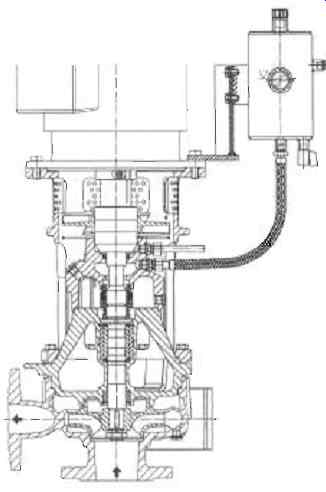
FIG. 1 A vertical mono-block pump with quench tank. Courtesy of Allweiler
AG
The pump units
The low cost pump units handle both low viscosity, synthetic heat-transfer oils up to 350 degrees as well as hot water up to 207 degrees with the identical material configuration. They make traditional water pumps with special seals obsolete.
The pump units employ a flexible modular system. Depending on the specific application, they are available in mono-block, bearing bracket and in-line versions. They are economical to produce and simple to maintain and a uniform combination of materials cast iron, nodular cast iron and 13% chrome covers all pumped liquids.
There are 12 possible combinations ready for the most diverse applications using a few basic components: the three design types, two casing designs, PN 16 with dimensions according to EN 733; and PN 25 with dimensions according to EN ISO 22858) and two bearing/seal combinations: Silicon carbide bearing combined with a balanced mechanical seal for hot water up to 207 degrees Carbon bearing combined with a non-balanced mechanical seal for hot water up to 183 degrees and most applications involving heat-transfer oils.
Temperature considerations
When synthetic oils are used, the application usually involves a high-temperature system where large temperature differences are a major factor. These make expansion movements within the pump unavoidable due to external forces that affect the pumps through the system and the piping. That is why pumps for synthetic oils in particular must be mechanically very durable and rigid, but without transferring too much heat to the bearing and shaft seal.
The range of pumps can handle this situation, since the process liquid lubricated bearing is no longer part of the bearing housing, but instead is now part of the casing cover. It is therefore possible to move the separating interface between the casing cover and the bearing housing even further toward the drive end. At the same time, the diameter of the sealing face/spigot and therefore the centre between the two parts has been enlarged. The result is an optimized, skeleton-frame-type structure whose mechanical stiffness equals that of bearing housings found on traditional centrifugal pumps. Making the inboard bearing part of the casing cover also increases the length of the thermal barrier protecting the mechanical seal and outboard bearing. In this way, a low temperature level is achieved without the need for cooling ribs. The position of the interface also enables additional savings, since it is possible to forgo a second 'seal housing' for the mechanical seal. See FIG. 2 and 3.
Since the plain bearing is located behind the heat barrier where temperature is lower, there is no possibility of dry-running in the bearing. In designs where the bearing is located directly behind the impeller, by contrast, dry-running can occur as soon as the pumped liquid gets close to its vapor point even when the pump is filled! Thanks to its lower temperature, liquid in the plain bearing of the pump is always sufficiently pressurized. Furthermore, optimization calculations have shown that, assuming the same bearing geometry behind the heat barrier, this design provides an ideal lubricating film thickness in the bearing, maximizing its effectiveness. The higher viscosity of the liquid more than compensates for the less ideal impeller cantilever length.
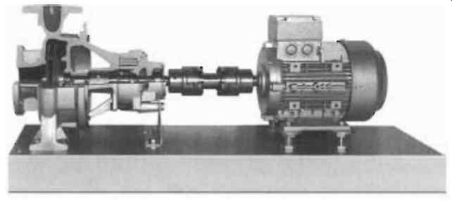
FIG. 2 The bearing bracket pump. Courtesy of Allweiler AG
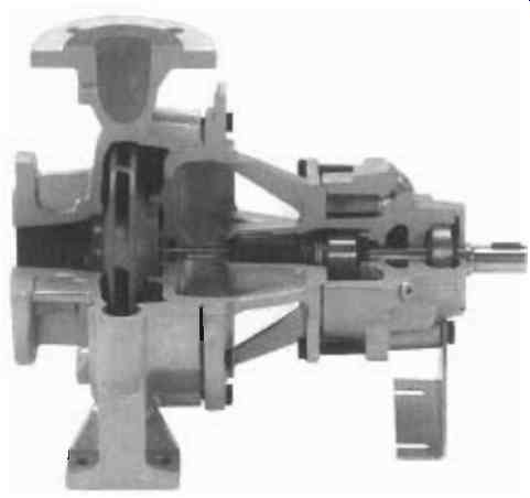
FIG. 3 Section through the pump
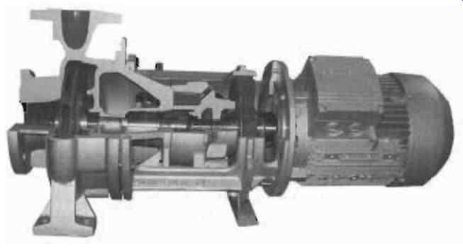
FIG. 4 Section through the mono-block pump. Courtesy of Allweiler AG
The carbon bearing
Practical tests have shown that the specific configuration and design of the carbon bearing generally result in a stable lubrication film. As long as the pumped liquid is free of particularly abrasive, fine-grain constituents, the carbon bearings will be subject to virtually no wear. Even normal contamination like corroded flakes from the pipes of hot water systems are not a problem, since a safety throttle keeps most of it away from the bearing. The throttle is located in front of the heat barrier and directly behind the impeller where it protects particularly against elevated leakage if the main seal fails. As a result, the bearing will achieve the stated long service times even when the pump is operated close to the minimum volume limit. The two bearing types carbon and silicon carbide are mutually exchangeable by changing the inner unit, which consists of the shaft, bearing and shaft seal.
The mechanical seal has been moved away from the impeller in the sealing area. The large-volume seal housing is designed to strip gas bubbles from the mechanical seal, collect the gas/vapor, and vent the pump. This protection against dry-running greatly lengthens the service life of the seal when pumping liquids with low lubricity that also tend to emit gas, even when the pump is in a vertical position. The bearing housing can also be used for the mono-block and in-line pumps, which are often installed vertically without loss of functionality. See FIG. 4 and 5.
Bearing geometry
For heat transfer pumps the bearings are not pressed in, but instead allowed to tilt. This has two benefits: First, if a bearing bracket is not aligned and centered precisely after maintenance, for example, it will automatically find its proper position.
Second, the bearing will move naturally if there is pressure from the shaft. This avoids point strains and lengthens service life.
A spacer coupling utilizing two Cardan joints is used for all high-temperature applications and especially for systems that exhibit large thermal growths. These couplings safely accommodate even very large misalignments. See FIG. 6.
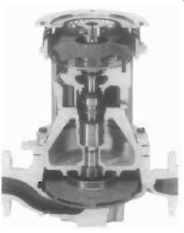
FIG. 5 Section through the in-line pump. Courtesy of Allweiler AG
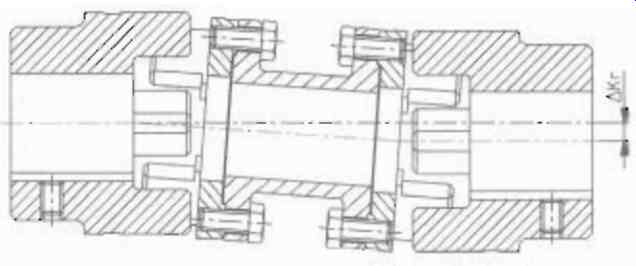
FIG. 6 Spacer coupling. Courtesy of Allweiler AG
Special heat-transfer pumps also provide a high level of investment security. If system is to be converted to modern synthetic oils, existing pumps can be adapted to the elevated temperature requirements by replacing the insert units. Such versatility from using a single pump type in a variety of heat-transfer liquids greatly simplifies processes for the operator and plant designer.
2. Pumping fresh water to a high reservoir
Operating conditions
The clean water collected in a low reservoir, is to be pumped up to a high reservoir. The high and low water levels in the two reservoirs and the altitude of the site for the location of the pump are shown in FIG. 7. The pipe linking the reservoirs is long, about 20 km, and during much of the day water is drawn from the pipe by consumers with consequent loss of pressure.
The daily consumption of water varies considerably. Furthermore, other water resources are operated simultaneously. For these reasons and also with regard to economy it must be possible to adjust the pumping from the water works in question from between about 50 to 115 liters per second. In cases of emergency, it should be able to pump about 170 inters per second.
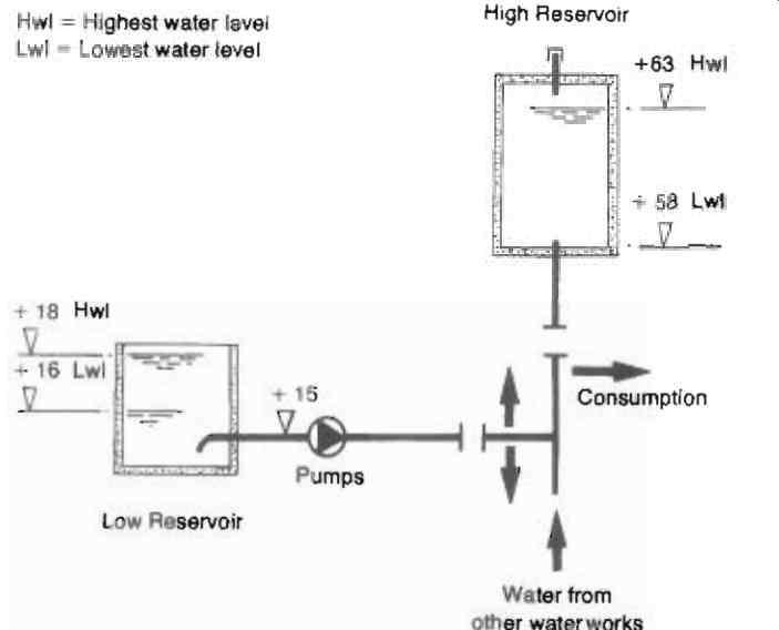
FIG. 7 The system
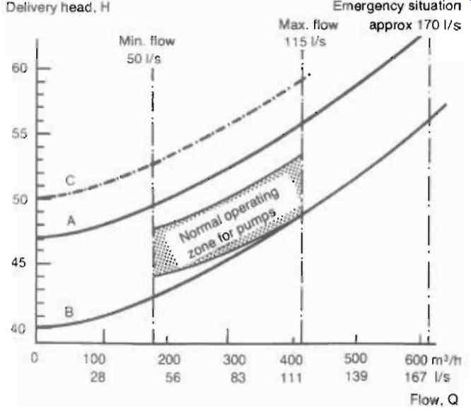
FIG. 8 System curves
System curves
The system curves are shown in FIG. 8. It proved possible to install the pumps 1 meter below the lowest water level in the low reservoir so that a positive head of 1 to 3 meters was obtained on the suction side. At the high reservoir the difference in height between high water and low water is 5 meters. The static delivery head in the system therefore varies between 47 m (+63 + 16) and 40 m (+58 + 18). The losses in the pipe system are shown by curves A and B in FIG. 8. From time to time the high reservoir may be disconnected for cleaning purposes or as the result of a breakdown. Pumping must then be directed to another higher reservoir and this results in an increase of static losses by about 3m.
Curve C illustrates the upper limit of the head requirement in this situation. The normal operating zone for the pumps is clearly indicated in FIG. 8. The highest operating efficiency should therefore lie within this zone.
Choice of pumps
On the basis of the great variations in flow demand, and respective head requirements found in this case, a combination of pumps was deemed necessary. However, it was scarcely possible to find space for more than three. High reliability of operation required that a stand-by unit should, at least to some extent be available. The necessary delivery heads implied that virtually only centrifugal pumps could be considered. From the running and maintenance points of view it was desirable that all the pumping units should be identical.
For the best possible reliability, company policy was to use pumps running at 4 pole motor speeds. Standard, double suction axially-split pumps would only fit the duty when running at 2 pole speeds. The use of three pumps would mean a motor power of 55 to 75 kW depending upon the pump efficiency. It had been decided to use a variable speed DC motor on one pump for supply adaptation. Mass-produced DC motors of the size necessary only ran up to 2200 rpm. Eventually a two stage axially-split pump was found; the first stage being double suction for good suction performance.
The pump curve is shown in FIG. 9. Curves calculated according to the Affinity Laws for 1200 and 1300 r/min are also shown in the Figure, as well as a combined curve for two pumps at full speed of 1450 r/min. The efficiency curve is also included in the Figure.
In FIG. 10 the pump curves have been overlaid on the system curves. As may be seen, the speed regulated pump provides the desired minimum flow at a speed between 1200 and 1300 r/min. Maximum flow was obtained with a constant speed plus the speed regulated pump. One unit was then kept in reserve. An emergency temporary demand of 170 liters per second can be met with all three pumps in operation.
The efficiency of the constant speed pumps is not the best in their normal operating zone, only about 70%, but it is better than that obtainable with faster pumps having cut-down impellers.
The maximum power requirement for the pumps selected occurs at H = 46 m and Q = 340 m3/h, see FIG. 9, and is 61 kW. The efficiency of the electric motor is estimated to be 90% and the pumping units are supplied with 75 kW standard 4 pole squirrel cage motors.
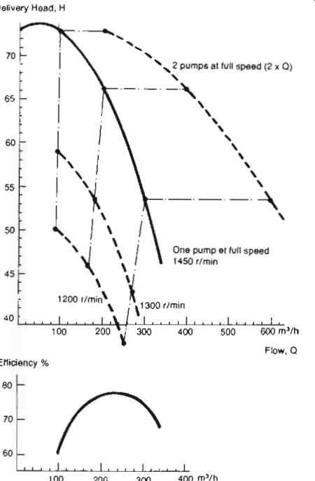
FIG. 9 Pump curves


FIG. 10 Pump and system curves
Installation of pumps
FIG. 11 indicates schematically how the pumps were installed. The pumps work in parallel with the speed regulated pump as the lead unit. When this reaches full speed, one of the two constant speed pumps is started; the constant speed pumps operate alternately, controlled by switched sequencing, and the speed regulated pump reduces to its minimum speed.
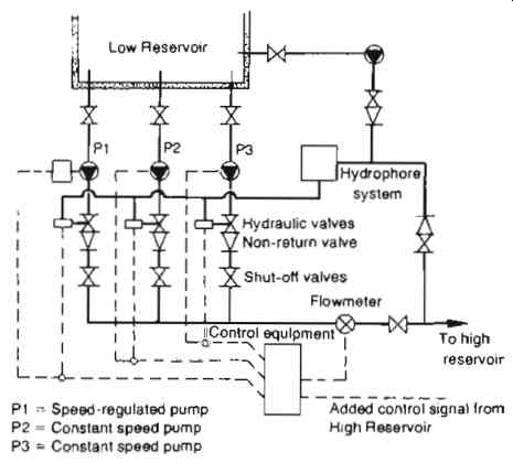
FIG. 11 Schematic arrangement of pump installation
In the case of increasing flow requirements it increases speed again. The procedure is the reverse in the case of decreasing water requirements.
Control of the variable speed as well as the starting and stopping of the constant speed pumps is regulated by a theoretical daily demand which in turn is constantly corrected by input from the water level in the high reservoir.
The delivery pipes of the pumps are fitted with hydraulically controlled, slow operating valves to reduce water hammer when starting and stopping. Pumps are therefore always started with the valve closed and when stopping the valve closes first. For safety reasons the pumps are also supplied with non-return valves.
3. A small sewage pumping station
Introduction
The pumping station serves a small housing estate. The supply of sewage during the initial period is a minimum of approximately 1 liter/s and a maximum of approximately 5 liter/s. It is estimated that gradually the minimum flow will increase to 2 liter/s and the maximum will increase to about 8 liter/s. The positive elevations at the pumping station are shown in FIG. 12. The rising main from the station is about 700 m long and discharges into a well at level +55 m. The diameter of the pipe is 150 mm and the volume is thus about 12.4 m^3.
As may be seen in the Figure, pump stop occurs at + 28m. The station has an emergency outlet, or overflow, at + 31m. The static delivery head will be maximum 55-28 = 27 m and minimum 55-31 = 24m. The stop level of the pumps has been placed as low as possible, approximately 250 mm above the floor in the pump sump, in order to avoid the formation of sludge deposits.
The station consists of two units, the pumping station itself and a valve chamber. The pumping station is constructed of pre-cast concrete rings with rubber joints. The internal diameter is 2m and the volume per meter of height is about 3.14 m^3.
The station is equipped with two identical submersible centrifugal pumps with quick release pipe couplings to allow quick pump removal. The pumps are started and stopped via level rockers, one of which is also used to transmit a signal to the control centre when the water level in the station is too high.
Level rockers are proprietary level switches which change attitude when floating on the liquid surface or are submerged.
In the valve chamber, which is also constructed of pre-cast concrete rings, there is a system of valves which ensures reverse-flushing of the pumps at every stop to prevent clogging.
During pump shut-down, air is introduced into the system via the non-return ball valve, the ball should have a specific gravity of 0.9 to function efficiently and the water in the rising main in front of the flap non-return valve flows back to the pumping station and flushes the pump clean. The amount which flows back in this particular case is about 90 liters. Thus for a short time the pump rotates backwards.
When the pump starts up it is impossible to prevent a slight jet of liquid being expelled through the non-return ball valve as this cannot be closed instantaneously. A spill water pipe returns the liquid to the pumping station.
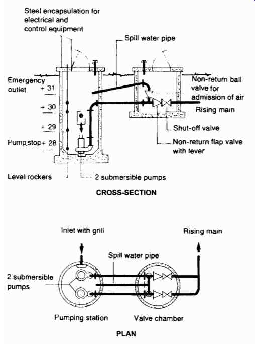
FIG. 12 Arrangement of a small sewage pumping station
Pump and system curves
These are illustrated in FIG. 13. As stated, the static rising delivery head can vary between 27 m and 24 m. The losses in the rising main and its valves are shown by the system curves.
The size of pump chosen has flows from 9 to 12 liter/s, depending on the differential head. FIG. 13 also shows the curve for both pumps in operation. The efficiency of the pumps in the operating zone is about 70%. The size of the motor is 9.6 kW, the normal output being about 6 kW, corresponding to a current of about 12 A. The pumps are started direct-on-line.
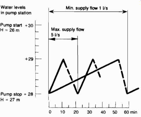
FIG. 14 Operating sequence with 1m working level.
Operating conditions
As mentioned, the flow of sewage to the station in the initial period is 1 to 5 liter/s. The volume of the pump sump is about 3140 liter/meter height. Pumping should occur at least once every hour to ensure water replacement. The start level of the first pump has therefore been provisionally adjusted to level +29 m, see FIG. 12, i.e. when 1 m of the sump is utilized. The operating sequences will then be as shown in FIG. 14. At minimum supply flow the sump used is filled in about 52 minutes, 3140/(1 9 60) and pumping takes place for about 6 minutes. Output is approximately 10 liter/s at Hmean = 26.5 m, see FIG. 14, minus inflow, i.e. 3140/((10-1) 9 60). As already mentioned, the volume of the rising main is 12.4 m 3 and after 4 hours the water in the pipe has been replaced. At maximum inflow the sump level rises sufficiently in 10.5 minutes and pumping out takes equally long, pump start occurring every 21 minutes. The pump motor is rated at 15 starts per hour.
Gradually, as the minimum and maximum rates of flow are increased, the sump volume will also be increased. FIG. 15 illustrates operating conditions at full supply flow and when 2 m from the sump, a volume = 2 x 3140, is used. This Figure also includes two curves, I and II, showing the time required for the emptying of the station from the emergency outlet level, e.g. after a power failure, with one pump in operation and minimum in-flow, I, and both pumps in operation and maximum inflow, II.
In calculating these times no allowance has been made for the reverse-flushing flow volumes. These, however, would be a marginal effect only.
As may be seen from this, normally only one pump is required to operate. Changeover takes place at every pump start so that both units are used. The second pump therefore acts as a standby and is started when the level in the sump exceeds the permissible value, +30.5 m. This situation can occur when:
- The lead pump fails
- The lead pump is partially blocked
- There is high rain water inflow
The station is monitored by an alarm system via telemetry and is inspected only once a week, when the sump is flushed clean and functional checks, etc., are carried out.
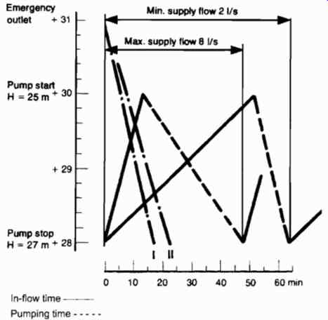
FIG. 15 Operating sequence with 2 m working level
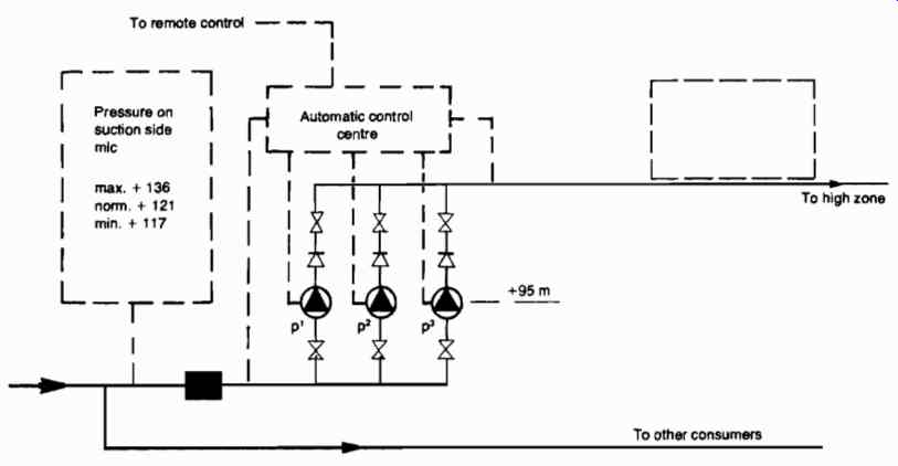
FIG. 16 Schematic arrangement of booster station and control system
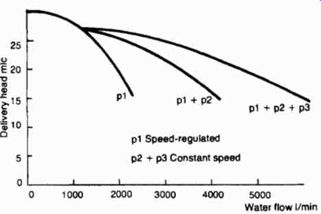
FIG. 17 Combined pump curves
4. A fresh water booster station
The function of the booster station is to create the necessary increase in pressure for the distribution of water in the higher areas of an urban district. FIG. 16 illustrates the schematic arrangement of the booster station and its control system, which has been in operation for 20 years or so.
Method of operation
Normally, the pump operation will be automatically adjusted to water consumption in the high area in such a way that the pressure in the distribution pipe is maintained more or less constant.
Adjustment to the actual pressure is affected partly by means of changes in speed of one of the electrically driven pumps and partly by changing the number of pumps in operation. Variable speed is obtained by the use of a DC motor.
Pump curves
The effects of running the pumps in combination are shown in FIG. 17.
Valves
Each pump has a manual isolation valve located in the suction pipe to the common suction header. Each pump is fitted with a non-return valve and an isolating valve in the discharge connection to the common header. The gate valves are of the full bore rising stem design. A mechanical indicating, totalizing flow meter is fitted in the booster station supply pipe.
Control
A pressure transducer, fitted to the distribution pipe, measures the changes in pressure caused by variations of consumption and transmits signals to the logic controller. This initiates the necessary changes in speed and number of pumps operating so that the pressure is restored to the predetermined value.
The pumping station operates without local personnel supervision. Control is performed by monitoring the water pressure on the delivery side of the pumping station with a local logic controller, in addition, certain fault condition signals are transmitted to the central control station.
Operating sequence
When water consumption is low, the speed regulated pump, p1, operates alone. Speed is increased as consumption increases.
When consumption surpasses the capacity of p l, either p2 or p3 is brought into operation. Which of the two pumps, p2 or p3, is to be started up is decided manually by a lag-lead switch or automatically by a timer. With the intention of reducing variations in pressure experienced when starting a constant speed pump, the speed of pump p l is reduced as another pump comes into operation. A similar procedure is followed when a constant speed pump is withdrawn from operation. At peak consumption all three pumps are in operation.
Limitations of operation
Pumping station operation is suspended in the case of insufficient pressure on the suction side or excessive pressure on the delivery side. Not until the pumping station has been inspected is it possible to start up the pumps again. The speed regulated pump can only be started at minimum speed.
Next: part 2
All parts: 1 -- 2 -- 3 -- 4 -- 5
Home Comprehensive
Pumping Manual top of page