AMAZON multi-meters discounts AMAZON oscilloscope discounts
20. Sealing systems for thermal oil pumps
Introduction
In industrial heating, thermal oil has become a popular heat transfer medium. Compared to hot water systems thermal oil can transfer higher temperatures at lower pressures. This means that hot oil systems allow a lower pressure rating. An electrical heater or burner heats up the oil, users consume the heat, and there is a circulation pump. The trouble-free operation depends primarily on a reliable circulation pump with a corresponding shaft sealing system. Every user of hot oil systems should be aware of the different sealing systems and pump concepts and their advantages. Using the cheapest pump solution often leads to high maintenance costs during operation.
Pump concepts
Low-cost centrifugal pump concepts normally use standard single-stage, end suction foot-mounted ductile iron volute casings with a standard single mechanical seal that is separated from the hydraulic parts by an air-cooled intermediate spacer. The temperature limit is typically 350 degrees However, in applications above 320 degrees this standard foot-mounted casing can be over stressed and distorted by typically unknown forces and moments generated by the piping system during heating of the plant. For temperatures above 320 degrees up to 400 degrees a pumping concept based on the standard chemical pump design is often a better solution. The pump casings can be equipped with center line mounting, see FIG. 58. The material can be improved to cast steel and different sealing systems can be used. When cast steel is used, it is also possible to use welded drain connections, which are much easier to seal than screwed connections. These are becoming more common in new installations, see FIG. 59.
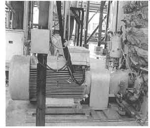
FIG. 58 Typical center-line mounted pump installation. Courtesy of Dickow
Pumpen KG.
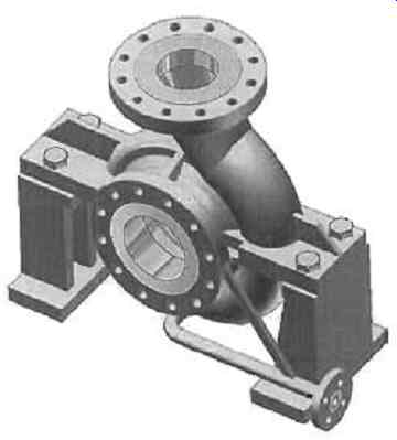
FIG. 59 Example of a volute casing with a centerline support. Courtesy
of Dickow Pumpen KG.
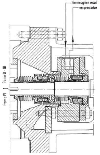
FIG. 60 Tandem bellows seal arrangement in a tapered seal chamber. Courtesy
of Dickow Pumpen KG.
Sealing systems
Especially for low viscosity and high temperature synthetic oils; e.g. Dowtherm or Diphyl; sophisticated tandem seal arrangements or magnetic couplings are required. In FIG. 60, an ideal tandem seal arrangement is shown. In order to minimize the influence of solids, such as decomposition sludge on the seal lifetime, the seal face combination is SiC against SiC (silicon carbide is a very hard ceramic material); the bellows are rotating in order to prevent clogging and the seal chamber is designed as large as possible to prevent the accumulation of solids and gases/vapors. The two seals, on both the product and atmospheric sides, are lubricated by an atmospheric air-cooled thermo-siphon vessel which also prevents damage to the seals, even during dry running conditions.
A constant lubrication and cooling circulation flow (of buffer fluid, e.g. oil) is generated by a pump ring. Failure of the product seal can be detected by a level switch in the vessel and the atmospheric seal will prevent leakage. For applications above 350 degrees it is possible to have additional water cooling with a cooling coil inside the thermosiphon vessel.
Another reliable solution is static shaft sealing by magnetic coupling, which is also air-cooled and is absolutely leak-free, FIG. 61. The operating principle of the magnetic coupling is very easy. There are internal and external rotating magnets that are separated by a stationary containment shell. This special pump design separates the magnets with an air-cooled finned section from the hot pump casing, which means that the magnets are running at a reduced temperature level, maximum 250 degrees. The magnets are also additionally protected against solids because they are separated from the main process flow.
Once again SiC against SiC is used for the liquid-lubricated bearings in order to minimize wear. The standard containment shell material is Hastelloy C. Eddy current losses are generated through the rotating magnetic field and these heat up the shell.
If the losses are more than 2 kW, the heat radiation of the casing will be too small and must be supported by an additional air-cooling loop. The standard design can even be improved with a close-coupled motor and a ceramic shell, FIG. 62.
The flanged motor prevents misalignment of the flexible coupling and the ceramic material has zero magnetic losses because it is an electrical isolator and non-magnetic. Secondary containment with a leakage monitoring device can be added for additional safety.
Field experience and application
In 2002 a leading Swiss heat transfer systems company awarded contracts for several heat transfer systems with multiple heaters for polyester plants in China. The heaters had a capacity of 14 to 16 MW. The selected heat transfer medium was synthetic Dowtherm A. Every heater generated about 157,600 kg/h vapor with a temperature of 337 degrees and a pressure of 3.5 bar. Process heating using thermal fluids in the vapor phase (flash system or secondary vaporizer) makes it possible to distribute a constant supply of heat uniformly to several users. The capacities range from 100 kW up to about 45 MW per heater, thus covering a broad spectrum of heating requirements. Even larger capacities can be achieved by combining several units in a battery, which also increases plant availability at the same time.
The circulation pumps of such a system are exposed to extraordinary conditions. At a temperature of 330 degrees a flow of 530 to 630 m^3/h against a head of 90 m must be circulated. The typical low-cost pump with a standard foot-mounted casing and a single mechanical seal, as described earlier, proved to be too weak for this kind of application. The low viscosity synthetic oil can additionally lead to leakage through the single mechanical seal. Therefore heavy duty hot oil pumps, were selected. A robust design with center line-mounted cast steel casings and a tandem seal arrangement were selected as the sealing system, see also FIG. 59 and 60. The first pumps installed have been running for several years without any major problems.
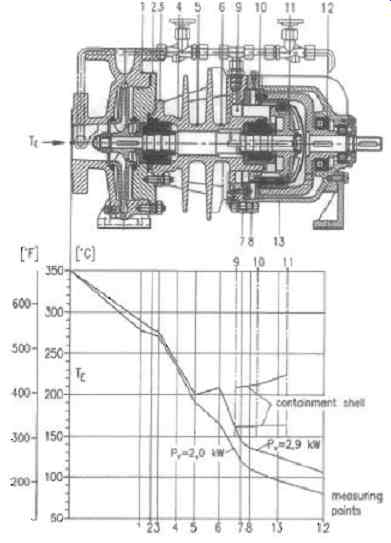
FIG. 61 Air-cooled magnetic drive pump showing temperature profile. Courtesy
of Dickow Pumpen KG
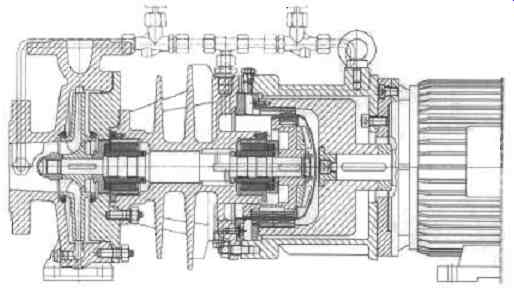
FIG. 62 Air-cooled magnetic drive pump with ceramic containment shell.
Courtesy of Dickow Pumpen KG
Pump selection
How can you select the right pump and sealing system? Unfortunately, there are no fixed temperature limits, it also depends on the piping and pump size, etc. In the region above 320 degrees and when using synthetic oils, it is strongly recommended to carefully examine the pump and seal design. When comparing double seal systems and magnetic couplings, the latter is not always more expensive. In regions up to 55 kW the initial costs of magnetic coupled pumps are even lower. For larger motors however (and therefore larger couplings), the double seal systems look more attractive. The longest MTBF (mean time between failure), up to ten years, can only be reached with an appropriate magnetic coupled pump.
21. Progressive cavity pump stator technology for improved candy production
Introduction
One of the oldest continuously operating candy companies in the USA undertook an expansion program involving a new, state-of-the-art facility which included a brand new moulding line for candy bar production. Before the move, the company had been relying on traditional positive displacement (PD) pumps to transfer the candy bar fillings from storage to the filling line. But, even as the company began planning the expansion, design engineers were encouraging management to consider progressive cavity, (PC) pumps, for the new facility, see FIG. 63. It was suggested that, among other benefits, PC pumps would run at the higher pressures needed for the viscous candy fillings.
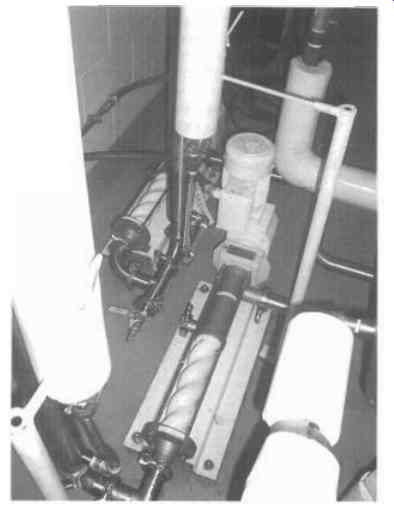
FIG. 63
The progressive cavity pump
In operation, a progressive cavity pump's single helix rotor rotates within an elastomeric double helix stator to form sealed cavities that progress from the suction side to the discharge end of the pump. The continuous seal between the rotor and the stator helices moves the product steadily, without valves or pulsations, at a fixed flow rate proportional to the rotational speed of the pump and independent of pressure fluctuations that can result from varying densities and viscosities of conveyed product. See FIG. 64.
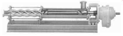
FIG. 64.
Several factors make these sanitary progressive cavity pumps the right choice for the new facility: The pumps use an Even Wall| stator, meaning the same performance can be achieved with a compact 2-stage pump that would usually require a much longer 4-stage with conventional stator geometry.
- The stators are also molded to size, not cut, with integral seals molded into the ends, and are offered in a wide selection of food-grade elastomers.
- These more economical and longer lasting, closed joint sanitary pumps are perfectly suited for candy fillings, whereas a dairy-compliant open joint would be unnecessarily maintenance intensive and expensive for this application.
- Their 'block,' or close-coupled, design conserves additional space.
- The units pump without pulsation; and at variable speeds they can be counted on to pump the fillings gently, with no shear or product damage.
Four sanitary PC pumps were purchased. They had Therban even wall stators, Duktil stainless steel rotors, and closed sanitary joints. The closed joint pumps are furnished with cost-effective pin joints and filled with special food-grade grease, making these pumps especially suited to high operating pressures. The pumps are rated to handle up to 0.25-US gpm on continuous service, customized for viscosity of 125,000 cP, at 120 degrees at pressures up to 24 bar.
The pumps are equipped with variable frequency drives for process control, with speeds proportional to a 4-20 mA signal coming from a level sensor on the filling machine. The space-saving block (close-coupled) design utilizes the gear reducer bearings to absorb the axial and radial loads of the pump. In fact, these units are assured of being capable of a minimum of an AFBM (Anti-Friction Bearing Manufacturers Association) L-10 life of 50,000 hours. Optionally, an L10 life of >100,000 hours is also available.
The block pumps require only simple bent steel 'top hat' base plates for mounting. Therban| is a proprietary hydrogenated nitrile butadiene rubber (HNBR) elastomer. The compound is made to CFR 177.2600 and is considered "food grade". HNBR offers superior abrasion and temperature resistance compared with NBR compounds or ethylene propylene diene monomers (EPDM) which are commonly offered for food applications. The HNBR in an Even Wall configuration has consistently outlasted NBR by a factor of five times or more in Even Wall stators.
Even Wall stators
Even Wall stators, see FIG. 65, are made with a special procedure using a metal tube that is hydraulically bent into a double helix, the same shape as the helix forming the cavity inside the pumping element. This makes the thickness of the rubber within the stator constant, as opposed to the thin and thick sections of elastomer existing in a normal cylindrical tube.
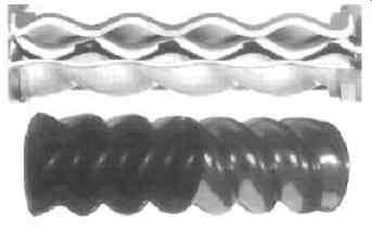
FIG. 65
Even Wall stators can handle twice the pressure of conventional designs on non-abrasive fluids, with an even smaller footprint than conventional PC pumps. Both hysteresis failures and bond failures are practically eliminated. These stators are excellent for food applications that have wide temperature variations that can result from low temperature operation and high temperature cleaning. Users report that these stators routinely last up to five times longer than conventionally designed stators in these applications.
Duktil is also a proprietary coating. Sometimes referred to as "chromium nitriding", it involves plating chromium at extremely high currents and heat. The result is a coating that exceeds a hardness of 90 Rc and actually diffuses into the base metal.
Consequently, it can bend (having ductile properties) without cracking, as standard hard chrome can.
Summary
The progressive cavity pumps currently transfer nougat, toffee, fudge and caramel fillings. The company has achieved savings by the minimal downtime required for repairs and in low energy usage. Additionally, the same pumps can be used for the four different fillings, with their viscosity variations, because of the variable speed possibilities and the ease of cleaning between operations.
22. Digital controllers for diaphragm dosing pumps with speed-controlled drive motors
Introduction
There are a wide range of highly sophisticated dosing tasks in water technology and process engineering which place high demands on dosing pumps in terms of precision, reliability and, in particular, monitoring the dosing process. Examples of these complex applications include dosing anti-scalants and antifouling agents in reverse osmosis processes and in the growth sector of diaphragm filtration. Further critical examples include dosing various biocides and defoaming agents in paper production and dosing cleaning agents and disinfectants in the case of CIP applications for the food and beverages industry.
Reliable dosing of concentrated acids and alkalis has proved to be a difficult task in the detoxification and neutralization processes of industrial process and waste water treatment. Industry continues to use conventional systems for dosing and process monitoring despite the high demands placed on them. The newly developed digital flow monitors can now help give the user precise control of dosing behavior. The diagnosis system detects errors in the dosing head and reports malfunctions reliably and without delay even at the lowest dosing rate settings in the ml/h range. (See FIG. 66)
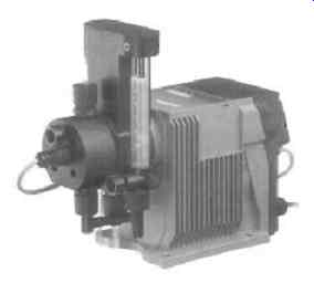
FIG. 66 Dosing pump with priming chamber and flow monitor. Courtesy of
Alldos Ltd.
Reasons for dosing errors
Among the most common causes of faults when dosing with diaphragm pumps are:
- Air and/or gas bubbles in the dosing head
- Cavitation bubbles in the dosing head
- Leakage in the suction or discharge valve
- Inadmissibly high operating pressure or system pressure fluctuations
Conventional solutions for monitoring volumetric flow
Until recently the most commonly used solutions for dosing monitoring in the case of diaphragm dosing pumps have operated according to the "floater principle". This method involves moving a float upwards in a pipe during the pressure stroke.
The float falls again during the suction stroke of the pump. This movement of the float is recorded visually, magnetically or inductively.
Adjustment of the dosing rate of the pump is then achieved by moving a switch and/or adding a bypass. This is precisely where the weaknesses lie. These settings have to be adapted to the relevant operating conditions of the pump and when changing the stroke length and/or the stroke frequency. This method of dosing monitoring can often not be used in the case of large variations in stroke frequency or when dosing viscous liquids.
Operating principles of the flow monitor
The indicator diagram displays the pressure profile across the suction and pressure strokes of the piston or diaphragm. FIG. 67 shows the pressure profile of a diaphragm pump which is functioning correctly. Starting at point 1, the pressure stroke features a compression phase with a build-up of pressure up to the opening pressure of the pressure valve at point 2 and this phase is followed by the feed process into the pressured line until outer dead center (point 3) is reached. During the return stroke, there is a drop in pressure down to the suction pressure at point 4 with a subsequent suction process until the inner dead center (point 1 ) is reached, i.e. the start of this cyclical process.
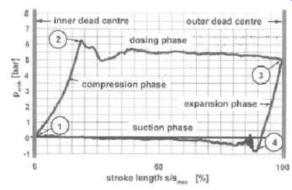
FIG. 67 Indicator diagram for a dosing diaphragm pump which is functioning
correctly. Courtesy of Alldos Ltd.
Error detection
A properly functioning diaphragm pump is used as a reference and stored in the microprocessor. Even minor faults can be detected by means of changes in the current indicator diagram.
FIG. 68 shows two frequently occurring faults in the dosing process through comparison with the error-free pressure profile (curve 1). Should there be air and/or gas bubbles in the dosing chamber (curve 2), pressure builds up more slowly due to the much greater elasticity. This means that it takes longer to reach the system pressure and that the dosing volume of each stroke is significantly smaller.
In the case of large errors on the suction side of the pump, extensive cavitation can occur as shown in FIG. 68 (curve 3). The reasons for this can be too small flow cross-sections, too low suction in pressure or excessive levels of suction or excessive viscosity. Vapor pressure dominates the entire suction stroke and only dissipates late in the pressure stroke. This scenario also results in a smaller dosing volume per stroke due to the delay in reaching the system pressure.
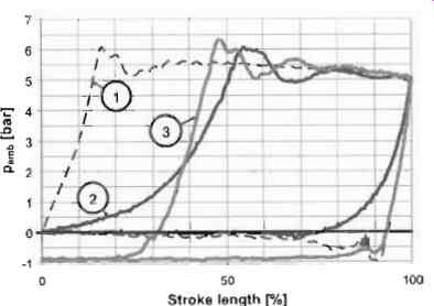
FIG. 68 Indicator diagram when pump is functioning correctly (1), when there
are air bubbles in the dosing chamber (2) and when cavitation occurs (3).
Courtesy of Alldos Ltd
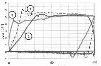
FIG. 69 Indicator diagram when pump is functioning correctly (1), when
there is leakage in the suction valve (2) and in the pressure valve (3).
Courtesy of Alldos Ltd
FIG. 69 shows two further frequently occurring faults in the dosing process through comparison with the error-free pressure profile (curve 1). If leakage occurs in the suction valve (curve 2), pressure builds up more slowly due to the leakage in the suction valve and the pressure falls before the outer dead center is reached as soon as the leakage rate is larger than the current flow rate of the pump.
Should leakage occur in the discharge valve (curve 3 in FIG. 69), a rise in pressure occurs before the end of the suction stroke when the leakage rate in the discharge valve is larger than the current suction flow of the pump. Moreover, the pressure falls more slowly at the start of the suction stroke as a result of post-flow in the discharge valve.
This indicator diagram is also suitable for detecting other faults; for example, if the set system pressure is exceeded. This can be identified and evaluated.
System solution
The dosing pump also incorporates a pressure sensor. This enables the existing microprocessor to be used for both motor control and processing the measurement values.
As can be seen from FIG. 70, the microprocessor continuously records the pressure in the dosing chamber and, using the motor control, the motor position which can also be used to determine the diaphragm position on the basis of the drive kinematics. This means that the microprocessor can generate the indicator diagram on a continuous basis. Evaluation algorithms have been developed to enable detection and evaluation of the dosing errors.
By setting the basic monitoring parameters for volumetric flow to cover a wide range of standard applications, depending on the error in question, a fall in the dosing rate of only 30% can be detected.
It is also possible to use the indicator diagram's memory of representative points and use them for the purpose of diagnosing errors. See FIG. 71.
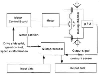
FIG. 70 Schematic of system used to generate the indicator diagram. Courtesy
of Alldos Ltd
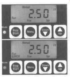
FIG. 71 Display when pump is functioning correctly (upper). Display when
there is a flow error (lower). Courtesy of Alldos Ltd.
The processor also takes an average of the values to continuously calculate the feed pressure in the dosing chamber. This value is representative of the current system pressure and can be queried at any time.
Summary
Continuous monitoring of diaphragm dosing pumps by recording and automatically evaluating the current indicator diagrams opens up many opportunities for operational monitoring: The current system pressure parameter enables a process to be established which is largely independent of the pump size.
The indicator diagram is largely independent of speed, viscosity and temperature. This establishes the same system for detecting errors across the pump's entire volumetric flow range without defining a working point.
Recording the current system pressure enables users to balance out pressure-dependent fluctuations in the flow rate of the pump by adapting the speed.
23. Positive displacement medium pressure pump system for tube press application
Introduction
The removal of waste iron ore from the furnace exhaust along with other waste products is an important stage in tube press processing of waste products at any steelworks. The ore is then re-processed into briquettes for re-cycling. The ore is transported via water which becomes a slurry. The key factor in this process is to extract the ore using the application of high pressure water to squeeze the slurry through a filter press. See FIG. 72.
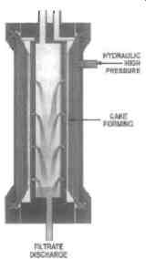
FIG. 72 Filtration system. Courtesy of RM/ Pressure Systems Ltd
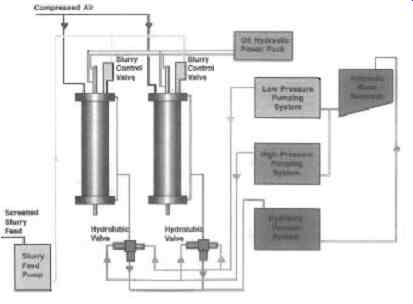
FIG. 73. Typical tube press flow-sheet. Courtesy of RMI Pressure Systems
Ltd
Technical application
As mentioned the key factor in the systems design is to a remove the ore from the slurry prior to fine filtering. The difficulty arises in that this is generally a medium pressure application up to 100 barg, relative to normal high pressure installations for steelworks applications of 400 barg, meaning that this was completely unsuitable for a normal centrifugal pump system.
The overriding challenge was to maintain pump control and system supply via a positive displacement pump system, which is inherently more complex then a standard centrifugal pump system. See FIG. 73.
The solution
A complete bespoke system was designed based around a standard crankshaft-driven reciprocating pump with a set of accumulators and nitrogen charged back up bottles (See FIG. 74 and 75).The pumps were then fitted with unloading valves and safety devices to ensure that a fine pressure hysteresis of the system was achieved.
In order for the system design to meet these specific criteria, a detailed analysis of system demand was extracted from the user's PLC system. From this data the pump duty was determined, the accumulator sized and the process parameters applied to the system.
These parameters had to ensure that the system achieved and maintained the following:
- The pump unit had to cycle on load-off load, every five seconds.
- The accumulators had to operate within 10% of the system's nominal pressure, with the option that this could be adjusted down to 5%. The plant in which the system is installed operates 24 hours a day, 7 days a week; therefore there was no room for error in the performance.
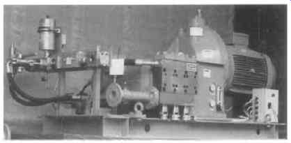
FIG. 74 The pump unit. Courtesy of RMI Pressure Systems Ltd
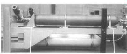
FIG. 75. Accumulator bank. Courtesy of RMI Pressure Systems Ltd
After installation
Following installation on site, a number of months were spent monitoring the system, assessing the performance requirements and then adjusting the system capabilities to suit.
One year later, a program of routine inspection is underway to ensure that the system continues to perform within the requirements of the technical criteria laid down and constantly monitor feedback.
24. Boiler feed pump for efficient power station operation
Introduction
With its 40 MW drive rating, this feed pump, known as "The Gentle Giant", was at the time of installation, the largest ever produced. It was built for Unit K, the latest addition to the Niederaussem lignite-fired power station near Cologne in Germany. See FIG. 76.
The new power station has a power output of 1000 MW and a net efficiency of 43 % making it one of the most modern and efficient stations in the world. To achieve such a performance, all components of the power station unit had to be perfectly matched to the process as a whole. The feed pump provides the total boiler flow without the provision of a back-up unit, and instead relies upon remote telemetry monitoring for condition based monitoring.
Plant outages are every power station operator's nightmare because of the immense costs involved. The pump, therefore, has to be very hard-wearing, insensitive to extreme duty conditions, and provide reliable service for long periods without maintenance. But that isn't all; energy supply companies also expect a very good efficiency. After all, every kW not consumed by the pump which is in operation around the clock--can be sold to its customers.
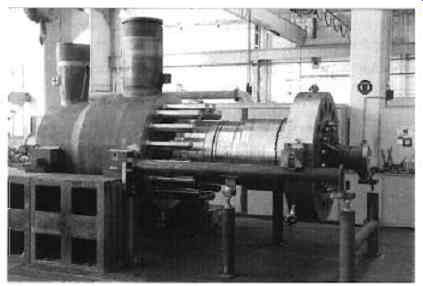
FIG. 76 Assembly of the feed pump. Courtesy KSB AG
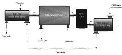
FIG. 77 Simplified schematic of the steam turbine and the two pumps. Courtesy
KSB AG
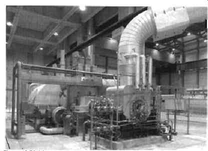
FIG. 78 A booster pump. Courtesy KSB AG
Turbine drives pump
The pump is driven by its own steam turbine with continuously variable speed control. The turbine has a power rating of 44 MW and is equipped with two shaft ends, FIG. 77. One shaft end is directly coupled to the pump. The other, on the opposite side of the turbine, drives a booster pump which supplies the main pump with the necessary inlet pressure, (see FIG. 78). The booster is not coupled to the turbine direct but to a gear which reduces the speed by a ratio of 3.5 to 1. Running up and low flow operation are normally taken care of by two electric motor-driven start-up pumps, each with an output of approximately 35% of that of the feed pump. During these phases of operation, the main boiler produces too little steam to operate the feed pump turbine. In exceptional circumstances, the steam needed to start up the pump and run up the turbo-alternator whilst the pump is still cold, can also be supplied from an auxiliary boiler.
Special vane profile
As the pressure in the system can change enormously in response to the operating conditions of the power station unit, the first stage with its impeller is the most sensitive section in every boiler feed pump. The plant operator's specification called for a minimum of 50,000 hours of operation without cavitation-induced wear. To meet this requirement, a special vane profile needed to be developed for the first stage impeller.
Computational fluid dynamic (CFD) modeling was used to design an impeller that would allow the pump to be operated without cavitation across the entire relevant operating range and with a sufficient safety margin from the system's NPSH available.
A number of special components had to be designed to meet the taxing demands made on the pump set. See FIG. 79.
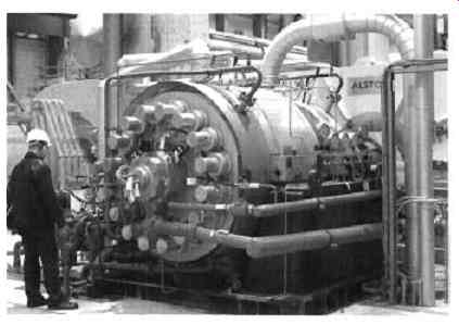
FIG. 79.
The floating ring seal is a case in point. This type of seal is very reliable, even at peak running speeds of 50 m/s and more, which are common on high specific speed pumps. Other exceptional features of the seal are its thermal characteristics and the way these positively affect the pump's operation. This will be discussed later.
Hydraulic design
At the duty point, the main feed pump is expected to have the following performance data:
Flow rate = 2898 m^3/h (m = 698 kg/s)
Differential head = 3361 m (Ap = 285.7 bar)
Inlet temperature = 198.4 degrees
Speed = 4620 rpm
Power = 26.47 MW
Efficiency = 86.9 %
At the so-called "TUV point", when the boiler relief valve starts to lift, the pump set reaches a maximum speed of 5217 rpm. It delivers hot water at a rate of 893 kg/s and has a power input of just under 42 MW (around 2 MW of which are required for the booster). The total head rise is divided among five stages, with a tapping downstream of the first stage.
As far as the hydraulic designs of the impeller and the individual stages are concerned, this gives us a specific speed of: nq =n.-=31 Equ. 13
H St 0.75
where: n = speed (min -1)
H = head (m)
Q = flow (m^3/s)
In terms of efficiency, total construction effort and cavitation properties, this value is very favorable for a high-pressure pump of this kind. From the design point of view, the hydraulic elements of the pump can be regarded as unproblematic. The geometries of the impellers and diffusers of stages two to five were taken from time-tested older pump models and converted to the required sizes on the basis of the Affinity Laws. There were some minor modifications to be made to the hub to accommodate the increase in shaft diameter on account of the higher drive rating.
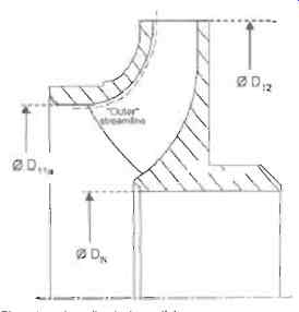
FIG. 80 First-stage impeller (schematic). Courtesy KSB AG
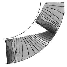
FIG. 81 Simulated flow patterns inside an impeller. Courtesy KSB AG
The first stage impeller
The most "critical" pump element from the point of view of fluid dynamics is the first stage impeller, which differentiates between the first of several identical stages and a special suction impeller design. The specification stipulated a guaranteed minimum period of operation of 50,000 hours without cavitation-induced wear. Cavitation, or rather the damage it does in the form of cavitation erosion and corrosion, is a major area of concern for the operation of turbomachinery.
Numerically speaking, the phenomenon is expressed by the NPSH value in pumps. It is governed by the following relationship:
NPSH a (system) >_ NPSH r (pump) Equ. 14
The NPSHa value denotes the energy made available by the system immediately upstream of the pump. It is expressed in meters and already takes into account the pumped liquid's vapor pressure, which is why it is commonly referred to as Net Positive Suction Head Available. It must not be confused with the NPSHr, Net Positive Suction Head Required, value of the pump, i.e. the energy required at the pump's inlet to avoid cavitation altogether or at least prevent it from damaging the pump internals. The NPSH "required" by a pump depends on the properties of the impeller material and the velocity of the flow in the impeller inlet area. The latter results from the circumferential speed u11a at the outer impeller inlet diameter, the tip speed of the eye. It is a linear function of the speed of rotation, FIG. 80:
ul~ a = =.Dl~a .n Equ. 15
The tip speed of the eye has a major influence on the so-called material loss rate VA, which is an indicator of the erosion phenomena caused by cavitation. Previous experience has shown that the material loss rate will become extremely high at tip speeds (Ulla) of more than 70 meters per second. Under these conditions, even impellers made of high grade materials will soon begin to show signs of damage if subject to the slightest cavitation. So, in order to guarantee the lifetime specified, the designer must make sure that the pump set can be operated at the main duty points without any risk of cavitation:
NPSH a > NPSH r = NPSH i Equ. 16
Consequently, the main criterion for designing the first stage impeller is to develop a geometry that will ensure non-cavitating pump operation.
Simulating flow in the impeller
At the blueprint stage, the design properties of the impeller were demonstrated by means of computational fluid dynamics.
The findings were then verified experimentally by cavitation testing. The design tool used for analysis is a method based on three-dimensional Euler equations. It simulates the flow patterns inside the impeller and provides information on the local pressures and velocities occurring at any point of the impeller passage, FIG. 81. The method is known to provide accurate data for this type of project and is a very good compromise between speed and reliability. FIG. 82 shows an example of this kind of analysis.
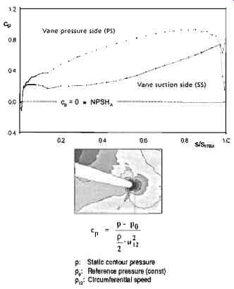
FIG. 82 Computed pressure distribution (example). Courtesy KSB AG
After a series of optimization runs produced the final contour, the "ideal" geometry has to be translated into the actual component with the highest possible degree of accuracy. To do this, the inlet areas of oversize vane blanks are reduced to their final dimensions using electric discharge machine tools. Another part of the optimization process reduces the interaction between the impellers and the stationary diffuser so that little or no vibration is produced.
Cavitation testing
To verify that the suction stage impeller actually gives non-cavitating operation at the "critical" duty points, the impeller was installed and tested as a single-stage pump on a cavitation test bench, FIG. 83, specially built for this purpose. On the inlet side of the impeller the test arrangement was fitted with a replica of the original suction elbow which featured a Plexiglas window to allow the flow behavior to be studied close up. The observed NPSH~ values had a sufficient safety margin from the NPSHa values and agreed very well with the computed values, FIG. 84. The plotted NPSHa values mainly resulted from the head of the booster pump, converted to the conditions of the test arrangement, whose main task it is to increase the pressure to the level required by the high-speed main pump.
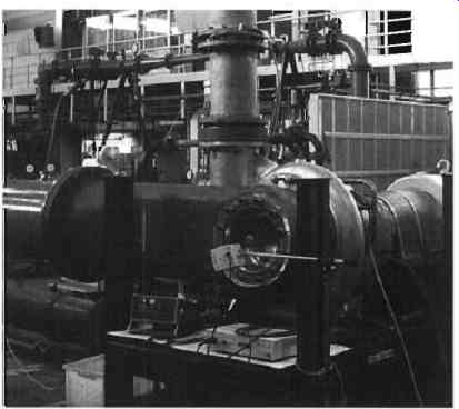
FIG. 83
The rotor
The power transmitted by the drive turbine is transmitted via the pump shaft to the impellers. These are mounted on the shaft by way of a rigid and wear-resistant connection, see FIG. 85, part 1.
The pressure distribution around the impeller gives rise to a hydraulic axial thrust, FIG. 86, which is transmitted to the shaft by means of a separate split ring for every impeller. The axial thrust, which increases in intensity from one impeller to the next and can eventually reach a maximum value of 11.5 MN, is reliably balanced by a doubled drum, FIG. 85, part 2.
Thanks to its hydraulic properties, the double drum is capable of permanently reducing the forces acting on the thrust bearing.
The thrust bearing is thus protected against overloading even in the event of sudden transient load changes.
The shaft bearings
Grooved multi-lobe plain bearings were selected as radial bearings based on the positive previous experience with this type of bearing in terms of load-carrying capacity and dynamic properties, FIG. 85, part 6. Like the thrust bearing, the plain bearings are lubricated with pressurized oil supplied from the turbine's oil supply system. The tilting-pad thrust bearing for load in either axial direction, FIG. 85, part 7, is reliably protected against a sudden reverse of the residual axial thrust. Together with the balancing properties of the double drum, the bearing effectively protects the pump against overloading and the harmful effects of sudden load transients.
The stationary components
One of the most striking things about the feed pump on first sight is probably the pressure boundary. It consists of a forged barrel casing, FIG. 85, part 8, and a cover, FIG. 85, part 9, which securely located by substantial studs and nuts, FIG. 85, part 10 is designed to retain the internal pump pressure.
The nuts are tightened with a hydraulic tensioning tool. This allows the nuts to be tightened without applying torsional shear stresses or bending stresses to the studs. These fasteners, which have to withstand higher loads than any others in the entire pump, can thus be designed with the required reliability.
Taking on 36.75 MN! The pressure forces generating the axial thrust on the rotor also have an effect on the stationary parts. For the main joint fasteners, which have to secure the cover against the internal pressure, this means they have to withstand a maximum load of 36.75 MN! A spring element, the compensator, provides a sufficient level of preloading of the internal components to keep them locked in place even during a phase of low internal pressure. It also compensates the different degrees of longitudinal expansion of the pump internals and barrel as a result of the uneven temperature distribution typically occurring during transient load changes. In a thermal shock, these differences can measure several millimeters in length, which have to be accommodated without affecting the installation's availability or causing damage.
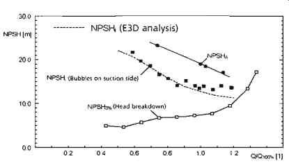
FIG. 84 Results of a "bubble visualization" test. Courtesy KSB
AG
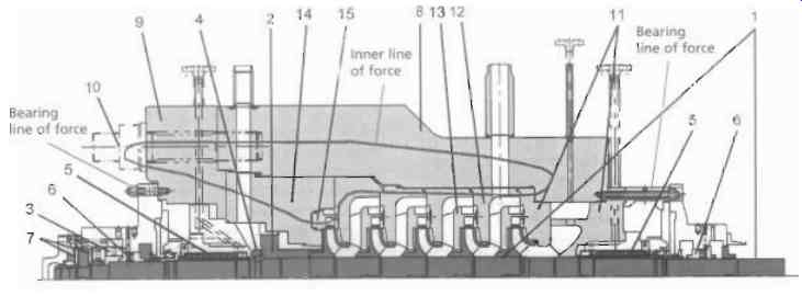
FIG. 85 Main lines of force acting on the stationary components. Courtesy
KSB AG
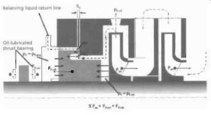
FIG. 86 Axial thrust balancing. Courtesy KSB AG
Temperature differences can also occur during start-up or as a result of an emergency shutdown. The internal hot water will stratify causing the top half to be much hotter than the bottom half and will cause jamming of the shaft and floating ring seals.
The drive turbine is, therefore, equipped with a small electric motor to keep the pump rotating or barring, at approximately 100 revolutions per minute. As the pump gains speed, the internal pressure increases the rigidity of the pump components.
The lines of action of the internal forces are crucial for the vibration characteristics of the pump running at full load. As well as a low-excitation hydraulic system an undivided line of action of the internal forces is of major importance. If the bearing forces can be separated from the hydraulic forces on entering the barrel (See the lines of force demonstrated on FIG. 85.) this will greatly benefit the pump's operating behavior.
One of the advantages of the low vibration level was that the pump produced so little noise that the originally planned sound-absorbing cover proved unnecessary. The static seal elements required to seal the pressure from atmosphere are designed as profile rings capable of sealing 500 bar(g) pressure maximum. Their sealing action is directly linked to the surrounding system pressure. It causes the sealing lips to be pressed against the components to be sealed. No other forces are needed to achieve the sealing effect. A further advantage of this seal type is that it does not reduce the joint pressure other parts need for their sealing function, for example the metal-to-metal sealing of the stage casings.
Shaft seals
In recent years, many power station owners and operators have learned the hard way that of all the components of a feed pump, shafts seals in particular are highly sensitive assemblies. They can make or break the availability of an entire power station. Since floating ring seals have been giving many years of reliable service in the older units of the Niederaussem power station, this seal type was selected for the new turbine-driven feed pump. In the seal, the pressure is relieved from suction pressure to atmospheric pressure along a multistage throttling distance made up of "floating rings". Depending on the pump's duty point, the pressure drop can be as high as 40 bar. As the pumped liquid flows through the annular gap between shaft and floating ring, it assumes a "bearing quality" which causes the ring to float, preventing physical contact.
To stop the flow of hot water from the pump into the seal from evaporating, and to prevent the throttling rings from losing their bearing quality as a consequence, the system has to be sealed with cold condensate. The condensate is injected at the end of the first throttling section. The injection rate is controlled by a regulating valve positioned at the inlet. As the cold condensate is mixed with the hot feed water from the pump, the heating rate of the total flow of leakage can be measured and the measured value taken as a parameter for controlling the valve. The leakage flows into a tank with level monitoring and is fed from there into the condensate system. Two 100 % pumps (one duty, one standby) supply the seals with barrier condensate, even if either pump fails. A simplified schematic of the barrier condensate cycle of the floating ring seal is shown in FIG. 87.
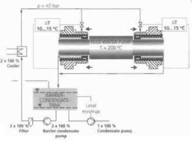
FIG. 87 Barrier condensate cycle of the floating ring seal. Courtesy KSB AG
Planned maintenance Whenever the pump shaft is turning, i.e. even when it is in barring mode, the barrier condensate system has to be in operation as well, because that it is the only way to stop the floating rings from coming into contact with the rotating shaft. After all, with planned maintenance intervals of between three and five years, the shaft seal system has to be absolutely dependable.
During the commissioning phase of the feed pump, the thermal characteristics of this shaft seal type proved particularly valuable. As there is always a liquid flow in axial direction through the section of the shaft where the floating ring seal is located, hardly any thermal stratification develops in this area.
A system equipped with a mechanical seal would respond differently. It would require heating jacket and circulation cooling, and the cold condensate, 60 degrees used by both cooling systems would continually create new temperature stratifications on being mixed with the hot feed water, 200 degree. Temperature differences of this kind develop above all when the pump is run in barring mode and may cause shaft deflection and/or deformation of the pump casing. The joint action of these effects can lead to such severe distortion that the rotor may rub against the casing in less than a minute. Typical consequences are overloading and failure of the barring gear. When this happens, the pump has to be cooled down to a much lower temperature so that the deformation is reduced and the rotor can turn without touching the casing. These processes are of paramount importance for the availability of a main feed pump.
A "well-tempered" pump
An event during commissioning demonstrated the excellent thermal characteristics of this truly "well-tempered" pump. Due to a fault in the turbine's control logic, the pump filled with hot feed water at 180 degrees did not run for all of 31 minutes. After that the automatic control system inexplicably returned it to service in barring mode. And the rotor started turning again smoothly! An incident of this kind would have normally caused any pump to seize! Remote monitoring accompanies commissioning.
At the request of the owner/operator, the pump unit is monitored by means of a complex tele-monitoring system comprising more than 50 pressure, temperature, vibration level and shaft orbit sensors. These sensors transmit the data collected to the tele-service center direct where they are stored in a database, ready for retrieval any time the specialists need them. Despite extensive prior computations, pump units of this size always require practical testing to develop and calibrate the most favorable models for starting up and stopping the pump.
These models serve to optimize the cold and hot running phases in the power station, which improves the cost efficiency of the plant without jeopardizing its availability. Based on the data supplied by the sensors, the pump designers study phenomena like thermally-induced stresses in and deformations of pump components, as well as their effects on the pump's running characteristics. This information aids condition-based maintenance and enables the pump manufacturer and plant operator jointly to determine the maximum permissible duty conditions of pump and peripherals.
Summary
With its 40 MW drive rating, the Niederaussem feed pump ( FIG. 88) was one of the most demanding of developments undertaken by its manufacturers at the time. Specially designed vane profiling provided the means to guarantee non-cavitating operation of the first-stage impeller, which was proven by theoretical analysis and experimental tests. The system pressure, the temperatures involved and its high speed of rotation subject the pump set to extreme mechanical and thermal stresses.
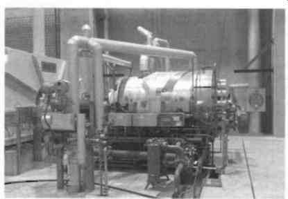
FIG. 88 Side view of the boiler feed pump. Courtesy KSB AG
As well as the bearing arrangement and the method of axial thrust balancing, the real technological highlight of the pump is the shaft seal, a sophisticated floating ring seal. Intensive in-house testing and data obtained during the commissioning phase at the power station provided ample proof that the pump met all of the technical and economic requirements originally specified.
Based on a technical paper presented by: Dipl-lng Thomas Elsasser KSB A G, Dipl-lng Bernhard Brecht KSB A G, Dr.-Ing Sven Baumgarten KSB AG, Dr Kirk Kollmar KSB AG