AMAZON multi-meters discounts AMAZON oscilloscope discounts
15. High capacity bearings for compact centrifugal pump systems
Introduction
Pump manufacturers are subjected to regular demands to reduce both the cost and the size of the pumping systems that they produce. The main focus of these cost-reductions is on centrifugal pumps because they are the most widely used and are the workhorses of industry, providing users with a wide range of flow, volume capacity, and head. They have uses in industries such as pulp and paper, wastewater treatment, steel mills, irrigation, mining and many other demanding environments. FIG. 43.
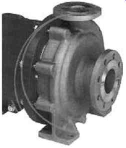
FIG. 43 Centrifugal pump example.
The need for compact bearings
The problem for any pump manufacturer designing more compact pump systems is that any reduction in size cannot be at the expense of flow. What this means for key pump components such as bearings is that they, in turn, must become more compact, but at the same time provide higher load capacity to meet new operating demands.
This requires the development of high load capacity, deep-groove ball bearings, resulting in improved basic dynamic load ratings of approximately 10% and fatigue life by around 30%, without any changes to the standard bearing dimensions.
These improvements have been achieved via a combination of a new heat treatment process, enlarged ball diameters, and by optimizing the interior design of the bearing cages. See FIG. 44.
Improved life and increased dynamic load ratings Table 2 shows the improvements that are achievable. The Table shows the boundary dimensions and basic dynamic load ratings of both standard and new high capacity bearings. Taking as an example a bearing with 30mm bore x 72mm od: in its standard configuration this bearing has a basic dynamic load rating of 26700 N and a high-load capacity rating of 29,800 N: an increase in basic dynamic load rating of approximately 12%. As a result of this, bearing fatigue life is increased by approximately 40% for similar load conditions.
Table 2 Improved life and increased dynamic load ratings
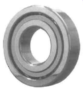
FIG. 44 High capacity bearing. Courtesy of NSK
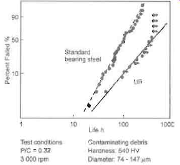
FIG. 45 Rolling fatigue life of bearing under debris contaminated conditions.
Courtesy NSK
One of the key factors in the longer life of the high-load capacity bearings is a new UR heat treatment process, which is effective in alleviating the stress concentrations that cause surface-originated flaking on bearing material. Surface-originated flaking tends to occur under contaminated lubricating conditions.
Stress concentrations develop immediately around indentations formed by foreign particles. The UR heat treatment process prevents this from happening, by increasing the amount of retained austenite within the bearing material. As a result, bearing durability is significantly improved in contaminated environments. This improvement is illustrated in FIG. 45. The graph shows that the life of UR treated bearings has improved by twice that of standard bearings operating under conditions of contaminated lubricant.
Another problem in pump bearing technology is that of creep.
This is the name given to wear that may occur between the bearing outside surface and housing bore due to low-speed sliding. It is the result of loads becoming excessively high on the driving shaft of a pump. If not addressed, creep causes excessive shaft vibration, which can trigger abnormal oscillation and lead to impeller damage.
Common measures against creep include an interference fit between bearing and housing. For pumps, however, a tight fit is not practical, as it makes pump assembly more difficult and does not allow for additional loading caused by an increase in the shaft length due to heat generation. A solution is to install O-rings into the two grooves on the bearing outer ring. The frictional force of the O-rings helps to prevent the occurrence of creep.
API 610 calls for angular contact ball bearings, with a 40 degrees contact angle, arranged in a back-to-back configuration, and giving a minimum life expectancy of 25,000 hours (3 years) continuous running, or 16,000 hours at maximum radial and axial loads.
It is claimed that these new bearings, by incorporating the one of the strongest machined brass cage available, provide effective reliability in the harshest of applications. They also achieve longer service life, through smoother running, reduced levels of friction and lower temperature rise; the latter as a result of the better heat dissipation of the brass cage material.
It is also claimed that they combine high strength materials technology, ABEC3 (P6) manufacturing tolerances and pump specific axial internal clearances to give high running and shaft positioning accuracy, plus optimum levels of bearing stiffness, as well as load sharing and cooler running. In addition, by the combination of super-finished raceways, low inner ring run-out and high ball grades, it is hoped these will contribute to a reduced level of ball skidding and, hence, smoother operation.
16. Energy recovery turbines and reverse running centrifugal pumps
Introduction
Pumps are usually purchased to pressurize a liquid. This then enables flow to take place by overcoming resistance in the piping system. In most cases, the pressure generated is entirely absorbed into the system.
In some cases the pump also has to generate additional pressure to start a process. Boiler feed pumps are one example of this. Here the system frictional resistance might only account for 30% of the generated pressure.
Reverse Osmosis, RO, is another example. Again, the frictional resistance only forms a small percentage of the generated pressure. Most of the pressure is used to stimulate the osmotic process of water purification. About half of the pressurized saline water fails to pass through the RO membrane. This is then discarded. Since this fluid is typically at 45 to 90 barg it must be depressurized before it can be dumped.
In a scrubber plant, impure gas passes through absorbent fluid in the absorber tower. Impurities are absorbed into this carrier fluid. This takes place at relatively high pressure. The fluid then passes to the stripper tower where the impurities are released.
To do this the pressure then has to be reduced, or "let-down". In the refining of oil to gasoline, the product passes through a hydro-cracking process. Again the charge product is pressurized to finalize the process. After reaction, this pressure has to be dissipated before the next part of the process.
In all these cases, liquid has been pressurized to permit some process to take place. It then has to be depressurized for some reason. A simple way of depressurizing the fluid is to pass it through an orifice plate. In this approach, all the energy embedded in the liquid is lost as heat and noise.
Another approach is to pass the liquid through a control valve.
This is not much different from an orifice plate but at least it is variable.
Energy recovery and its uses
Yet another approach is to pass the fluid through a turbine. This might appear to be an expensive solution. However, it has the advantage that not only is the liquid depressurized, but the energy embedded in the liquid is largely recovered. The value of this power can then be offset against the turbine cost. Experience has shown that this recovered power can repay the cost of the turbine in 9 to 18 months. After that the energy recovered is almost free. On this basis, it is almost irresponsible not to explore all possible uses of energy recovery turbines. How can the energy be used?
- It can be used as the sole power source for another machine
- It can be used to contribute power to another machine and reduce the power consumed by the motor
Reverse running pumps
Conventional turbines are expensive when compared with pumps of the same power. They are not so readily available, nor is the choice so great. The material options are also more limited. For special applications, such as high temperature refinery service the choice is very limited. Fortunately, all forms of centrifugal pump can also be run in reverse to perform as very effective turbines. The disadvantages of commercial turbines are then eliminated. The only shortcoming of reverse running pumps is that their efficiency is lower than a true turbine. However, this is typically only two or three per cent and hardly impacts on the pay-back period. The notation of reverse running pump is as shown in FIG. 46.
One apparent disadvantage of any turbine is that it needs some form of speed control. Fortunately this can easily be overcome in most cases. This depends upon the turbine being connected into a train that also utilizes an electric motor. Electric motors lock into the mains frequency and act as excellent governors.
This establishes the speed control the turbine needs.
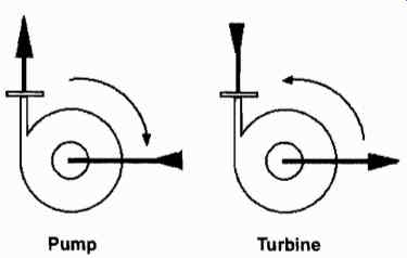
FIG. 46 Schematic notation of pumps and turbines
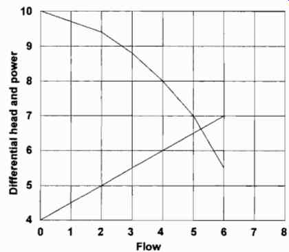
FIG. 47 Typical centrifugal pump characteristics.
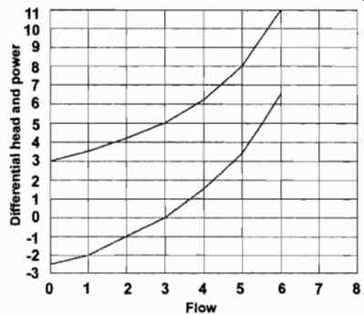
FIG. 48 Typical inward flow radial turbine.
Fundamentals
The performance characteristics of centrifugal pumps are well known. Those for a turbine are less well known. They are compared below.
FIG. 47 shows typical pump performance characteristics.
Generated pressure decreases as pump flow increases. On the other hand, absorbed power increases with flow.
FIG. 48
FIG. 48 shows the characteristics of a pump used as a turbine, i.e. the flow direction and direction of rotation are reversed but the pressure differential is the same. Note that the differential pressure increases as the flow increases. Also that the recovered power increases with flow. However, below a certain flow, the turbine actually absorbs power.
FIG. 49 shows the most popular way of connecting a pump and energy recovery turbine. The clutch is optional and its effect is shown by referring to FIG. 48 and 50.
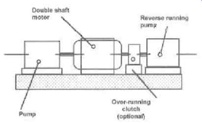
FIG. 49 Typical arrangement of energy recovery turbine with a motor as
the main driver
Effects of power recovery
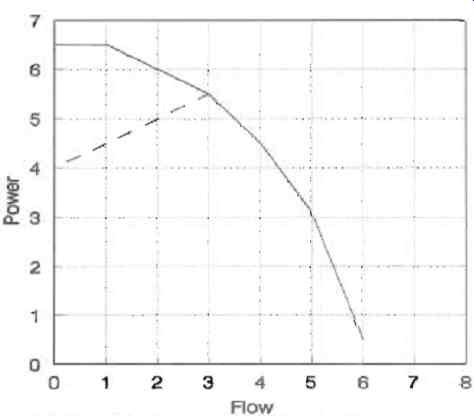
FIG. 50 The effect of coupling an energy recovery turbine
FIG. 50 shows the effect of coupling an energy recovery turbine in-train with the pressurizing pump as shown above.
This shows the net power delivered by the motor. It is calculated by subtracting the power recovered in the second chart from that absorbed in the first chart.
This net power curve should be compared with the unassisted power curve shown in FIG. 47. Note that at low flow, the motor is actually overcoming the power absorbed by both the turbine and the pump. As flow increases, the turbine begins to contribute and reduces the motor power requirements.
One way of reducing the low flow power demand is to install an overrunning clutch between the turbine and the motor. In this way the turbine is uncoupled from the train during starting at flows where it is absorbing power. It only becomes connected when power is being contributed.
17. Common errors which create pump operating problems
Most pump users and system designers do not think about pumps eight hours a day, every day; they think about pumps occasionally. Important factors revealed on the last project may not be remembered on the current one. Staff who gained good experience on the last project may have been transferred to a different department. The current project team may not have worked together before and an individual's depth of experience may be an unknown quantity. Most engineers rely on a web of personal contacts for support in "grey" areas; younger engineers may not have this backup support. The project manager must assess the qualities of all the project team and assign tasks accordingly.
Planning of pipework
In theory, starting a project from a clean sheet of paper, with an empty site, is the easiest type of project. But there does not appear to be a consistent logic applied to equipment arrangement and pipe runs. It seems obvious that the heaviest or biggest equipment must be located firstly where access is very good and adequate support is available. Heaviest/biggest equipment should be located around the periphery of the "plot" to provide the best access from outside. Heavy equipment should be located at ground level or as low as possible. Equipment which vibrates requires special consideration if the vibration is not to be transmitted through the supports. Many positive displacement pumps produce vibration and this factor must be considered when deciding locations and supports.
A number of pieces of equipment are not used in isolation but connected to other equipment. Pumps are connected into systems by pipework. Project planning should allocate priorities to pipework to allow "difficult" pipework to have good pipe runs while "easy" pipework can be fitted in the spaces left over. The choice of "difficult" and "easy" is not necessarily straightforward and requires some thought. The following points though should be considered:
- Size
- Pressure rating
- Differential temperature
- Water hammer effects
- Pressure pulsations
- Viscosity
- Essential routing requirements
Large pipes are obviously much more difficult to handle than small pipes. Access requirements around flanged connections may result in much wasted space. Pipe supports from the ground may be the only feasible solution. Space requirements for bends may preclude changes in direction and a straight pipe between A and B may be the only feasible option. Large pipes tend to be low pressure, although not always; and it may be worthwhile calculating the pressure times bore area; this can be used as a quantitative measure for priority. Higher pressure ratings require thicker pipe walls to reduce stressing to acceptable levels. Thicker pipe walls increase the difficulty of bending the pipe and increase the size of welds. The weight of pipe per unit length divided by the nominal diameter can be used as a priority factor. Piping which operates hot or cold, say 50 degrees or more above or below the ambient temperature, may require extra space to include axial flexibility to cope with thermal expansion/contraction. The differential temperature divided by 50 can be used as a priority assessment. The fluid flowing through pipes possesses dynamic properties -- kinetic energy.
Pipework systems cannot always be steady-state. A piping system must start up and sometimes it must stop; emergency stoppages, due to process upsets may be the worst case.
Water hammer effects should be evaluated. The liquid density is also an important factor. Water will produce much larger pressure changes than air for the same dynamic conditions. The water hammer effect can be judged by multiplying the pressure change by the pipe bore area. Pipework with large water hammer effects should be given a higher priority than lower ones. If these effects are likely to happen often, more than 7000 times over the whole life of the system, the pressure effects on fatigue should be investigated. Some equipment connected to pipework may not have a steady flow characteristic.
Some positive displacement pumps have significant cyclic flow variations which produce pressure pulsations. The flow variations produced by reciprocating pumps are well documented although the values given are usually wrong. Reciprocating pump flow variations are a variable not a fixed value. Peristaltic pumps produce very noticeable flow variations. Lobe pumps and circumferential piston pumps can have cyclic flow variations which are large enough to produce troublesome piping vibrations. The system designer or piping designer must select a value of acceptable pressure pulsations which is appropriate for the pipework construction and supports and for all the equipment connected to the pipework.
Delicate instrumentation, such as flow meters, may require lower pulsation levels than those dictated by pipework mechanics. Pipework subject to pressure pulsations should be given a higher priority than pipework with steady-flow conditions. An early routing schedule should allow a better chance of providing a straight pipe, which will not vibrate, rather than having a number of bends to avoid existing equipment. Systems for high viscosity liquids should be allocated a higher priority than water-like liquids. The choices for suction pipe route options may be extremely limited when the liquid has flowing difficulties.
Short, straight pipes with good fall are essential.
Pipework routing can be very important. Suction pipework which is not self-venting can pose tremendous installation problems if vent lines must be run considerable distances for safe disposal. Pipe falls are very important. Short pipes are better than long pipes. Straight pipes are much better than pipes with bends. Suction pipework is eliminated when submersible pumps are used. Cavitation is the most frequent pump problem. Using a submersible pump should help to eliminate a lot of the possible causes of cavitation. Liquid systems should be given priority over gas systems; compressors do not cavitate.
Logical project planning does not seem to work very well.
Pipework for high risk applications and high pressure, viscous liquids with pressure pulsations, seem to be always fitted as an afterthought. The system components are far apart and the pipe runs are never straight. Pipe supports are poor and pipe anchors are frequently non-existent. It appears that no sensible criteria are applied to priorities equipment positioning and pipe run locations.
Liquid properties
The proper selection of the best pump type is based on a good description of the operating conditions and the liquid properties. Pump specifiers and users have a habit of concentrating on "maximums" and forgetting about the "minimums". All operating conditions are important. The range of operating conditions is very important when evaluating pump performance.
The pump manufacturer does not provide guarantees for undocumented conditions.
The NPSHa/NPIPa available is very important. Cavitation is a very serious problem and increasing NPSHa or NPIPa is not usually easy. Reducing the pump NPSHr/NPIPr usually means operating at lower speed and flow. The vapor pressure of the liquid is a critical factor in the NPSHa/NPIPa calculation. The vapor pressure of a trace element may be significant. Small quantities of water in high temperature processes can produce a very large volume of steam relative to the liquid volume of the other components. Centrifugal pumps may lose prime with a 15% gas volume. Reciprocating pumps may suffer major component failures with a 5% gas volume. The vapor pressure of the liquid may not be important if dissolved gas evolves from solution. The apparent vapor pressure, the pressure at which gas bubbles appear, may be considerably higher than the liquid vapor pressure. Entrained gas creates cavitation-like symptoms; early component failures can be expected.
Very small quantities of solids can increase component wear dramatically. Materials of construction are adjusted when solids are included in the duty specification. The pump operating speed may be reduced to compensate for wear rates. It may not be possible to successfully adapt an installed pump to cope with solids. Reduced flow and high spares usage are the usual effects of handling unspecified solids.
The pump manufacturer assumes all changes in operating conditions are slow unless specifically identified as rapid. Temperature changes are slow enough not to create thermal shock.
Pressure and flow changes are also slow enough not to create surge problems. Rapid changes in conditions are very likely to cause early failure of major components. The cost of spares and lost production will be high.
Equipment positioning
The early planning of systems must include the relative positioning of the system components. The importance of good positioning increases as the "liquid" becomes more difficult to handle. In some processes "liquid" is a poor description of the process medium. Viscosity can be so high that the process medium will not flow under the influence of gravity; positive assistance is necessary for flow to occur. When the process medium has very high viscosity it is sensible to arrange the medium to fall into the pump. Trying to lift the medium into the pump is not a good idea. System planning should organize the suction source to be above the pump suction connection. This approach is always a good idea even with water-like liquids. The suction source should be as close as possible to the pump to reduce piping losses. Difficult liquid applications should have the equipment locations allocated very early in the project calendar and before easy systems such as water and gases.
Many systems rely on atmospheric pressure to provide the pump suction pressure. Atmospheric pressure is not constant and varies with the weather conditions. The standard barometric pressure, at sea level, is 101.325 kPa. Weather conditions cause a variation of about +3%. Most importantly, many installations are not at sea level. At 500 m the standard air pressure has dropped to 95.461 kPa and at 1000m to 89.876 kPa. From a water pumping perspective the effective suction lift of a pump is reduced by about 0.5 m for every 500 m of altitude. Also of interest is the variation in "g". At sea level the standard value is 9.80665 m/s 2. At 500 and 1000 m the standard values are 9.8051 and 9.8036 m/s 2. In pumping the only constant which can be relied upon is degrees.
Pipework design
Pipework design is very difficult. This is why many installations are poorly designed and suffer reliability problems and fatigue failures. Most piping appears to be designed by software which only considers "Code compliance", that is stressing which guarantees insurance cover. The prime function of the pipe, to carry fluid, does not seem to be considered; hydraulic considerations are usually ignored. In many cases the final pipework design is safe but completely unsuitable for the purpose.
Hydraulically, the best pipework is straight. Bent pipes are better than pipes fabricated with pressed bends. Pipework which is likely to be subjected to continuous pressure pulsations requires special attention. Pressure pulsations cannot create pipe vibration if the pipe is straight. Pressure pulsations act on bends to create the vibration. Sharp bends, pressed bends, create more vibration than gentle bends and bent pipe.
Experience has shown that 45 degrees sets, used in pairs, perform much better than bends.
Pipework which is likely to be subject to continuous pressure pulsations requires very good support and restraint. Pipework suspended by hangers will generally vibrate unacceptably and the vibration may induce unacceptable stressing. This pipework must be supported by clamps incorporating damped restraints and with rigid anchors at strategic locations. It may induce structural vibration if clamped rigidly, at high elevations, to building steelwork. The best results are obtained with low level pipework supported directly from concrete.
Successful pipework design can only be accomplished when the designer considers the actual hydraulic process which is taking place inside the pipe. The design must be appropriate for the hydraulic conditions. All pipework is not equal.
18. Positive displacement pumps load-unload control systems
Introduction
There are several applications where load-unload control has proved to be the best practical solution. Steelworks hydraulic power supply and steelworks descaling are two typical applications which only differ in the process liquid. Very large high pressure systems have used multi-stage centrifugal pumps with load-unload control and these pumps suffer similar problems (broken shafts) when the control system deteriorates or is inappropriate.
Steelworks use hydraulic power to actuate and drive much equipment. Equipment located close to hot metal poses a fire risk if hydraulic oil leaks and is ignited. For this reason many hydraulic systems have utilized water or water-oil emulsions. The lubrication qualities of water can be significantly improved if 5% or 3% soluble oil is included without resulting in a flammable liquid. Descaling utilizes cold water to produce thermal shock which violently fractures and loosens the scale on hot metal surfaces. Centralized hydraulic systems and centralized descaling systems operate at pressures of 100 barg up to about 450 barg. Plunger pumps are used when flows up to approximately 120 m3/h from each pump, are required. Small systems would use three pumps, two operating and one standby. Large systems may use five to ten operating pumps with two standby units.
Typical system
Water, or water/oil emulsion, is stored in a header tank at an elevation to provide sufficient NPIPa for the pumps. Water/oil emulsion must be continuously recirculated around the tank to prevent separation and also to allow oil concentration monitoring so the oil content can be adjusted if required. The feed from the header tank flows via a pair of strainers, one working/one standby, to the suctions of the three pumps. Each pump has a flow-through suction pulsation damper and a discharge pulsation damper. The flow-through style of damper is preferred for multi-pump installations because the degree of uncoupling between the pump and the system is much higher than appendage styles. There is much less chance of pump interaction affecting the system performance. The pump relief valve is located immediately after the discharge damper. The load-unload bypass valve is mounted before the non-return valve and the isolating valve. The one or two operating pumps feed a bank of accumulators which are used to store high pressure water. The use of accumulators allows the system to supply instantaneous flow rates much greater than the nominal pump capacity. As hydraulic power and descaling requirements are intermittent, the accumulators and the pumps can supply the peak demands. The pumps can recharge the accumulators when demand is low.
Electric motors
Load-unload control is better than on-off control because the electric system, starter and motor, are not subjected to the effects of high inrush currents. Motor starting, especially when hot, may be severely restricted for motors over 45 kW. During bypass operation the motor and the pump absorb very little power. Power consumption can be reduced even further if a modern soft starter is used. Modern soft starters often include a low power and/or low speed unload control. The motor is able to operate efficiently at low load and possibly at reduced speed.
Load-unload control can be applied very rapidly without overheating the motor or wearing out the contactor. Load-unload is not instantaneous but requires a finite time to change from low-pressure bypass to high-pressure on-load. Sizing of the accumulators is critical for the load cycle to operate smoothly.
Operation
These types of intermittent system are controlled by pressure.
As the system flow demand reduces, the pump over-capacity is absorbed by the accumulators; this causes an increase in system pressure. When the pressure reaches a predetermined value, say 85% of maximum, one pump is unloaded. If the pressure continues to rise the second pump will unload at 100% pressure. At this condition the maximum volume of water is stored in the accumulators and the total pump flow is zero. If the system pressure remained constant at 85% then the system demand would be equal to the flow from one pump. If the system pressure decayed, because the demand was greater than a single pump flow, the unloaded pump would be loaded to prevent the system pressure reducing below a preset minimum.
This mode of operation describes the traditional control system which used fixed pressure set-points, pressure switches, to initiate control sequences. Systems using a PLC and pressure transducers, would consider the static pressure and the rate of pressure change to decide on load-unload set-points. The set-points would be variable rather than fixed.
Bypass valves
Load-unload systems suffer two recurring problems. Both multi-stage centrifugal pump installations and plunger pump installations suffer when an inappropriate bypass valve is used.
Plunger pump installations frequently experience pipework vibration problems. The bypass valve is nominally an open or closed valve. In practice the valve must be slow-acting and have good throttling capabilities. Many installations are built with power actuated open/close valves, powered isolating valves, and the cycle time is preset. Because of the poor part-open flow characteristics of isolating valves the high pressure system is subject to surge and pressure pulsation problems.
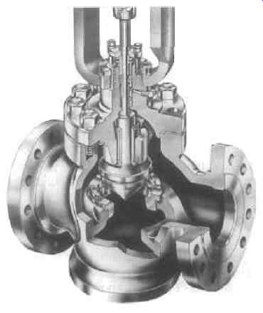
FIG. 51 Typical high pressure control valve
In extreme cases pump components such as centrifugal pump shafts, crankshafts and plunger pump crossheads, fail due to fatigue induced by the shock loadings. Hydraulically actuated valves, using the process water for actuation, have generally been unsuccessful because of the poor lubricating qualities of the water. The bypass valve should be a pressure control valve, see FIG. 51, which has specific throttling characteristics.
The globe valve shown has a contoured plug which provides a guaranteed throttling characteristic. The pressure rise during valve closure can be smooth and progressive and eliminate all surge effects. This style of control valve would normally be pneumatically operated but could be electrically operated. If a PLC was used for system control the bypass valve could be modulated to provide 0 to 100% pump flow for low flow situations. Pipework vibration can be experienced by centrifugal pump and plunger pump installations which try to use inappropriate bypass valves.
The flow surge created by an "isolating" valve opening or closing produces an associated pressure pulse. The pressure pulse causes pipework vibration. The pipework vibration is usually of very short duration but can be violent. Pipework failure through fatigue is possible. Short duration vibration can also be triggered by the equipment using the high pressure water or water/oil emulsion. If the equipment isolating valve is not slow-acting or does not have a good throttling characteristic then surge associated failures are likely.
Damping
Plunger pump installations frequently experience continuous high levels of pipework vibration. Pipework routings are usually far from ideal and elevated pipework may be suspended from building structural steelwork rather than the preferred low-level pipework firmly attached to the ground. The high vibration levels are due to a mismatch between the pump damper specification and the pipework construction style. The pump manufacturer is not usually involved in pipework design. If the system designer does not specify an appropriate level of damping for the distribution system the pump manufacturer will only provide a damper based on the pipework design local to the pump. The system designer is responsible for the correct operation of the whole system. Pump residual pressure pulsations are easily transmitted through the whole system and can create vibration anywhere. Co-ordination and communication are the keys to Success.
19. Plunger pumps for supercritical extraction service
Introduction
It is claimed that by using carbon dioxide supercritical technology, purer and therefore more valuable end products may be produced. Optimal process results relative to product quality depend upon the ability to control the process parameters in the high pressure loop. As control of the carbon dioxide process parameters requires sophisticated techniques and knowledge, so does the design of reciprocating pumping equipment to be used in these processes. The combination of these conditions give rise to the desired operating characteristics now described.
Background
Carbon dioxide supercritical extraction is a far reaching separation-oriented process that is growing in commercial application.
Early commercial plants were designed in 1973 and went into service in 1979. Since then many additional and larger plants have come into operation. The efficient application of this process technique requires highly reliable and functional capability of the more important system components. Thus the pumping equipment required to pressurize the carbon dioxide liquid is a key process component.
Applications
Food and pharmaceutical industries require the extraction of basic, rare, aromatic and/or taste substances for economic productivity and high product quality. Although supercritical separation technology has been well known for many years, it has only recently been used for industrial scale manufacturing applications. The prime application is in the extraction of substances from plant life raw materials.
The prime benefits of the supercritical extraction process relate to the non-destructive handling of the raw material and in addition the desired end product has an extremely high degree of purity. Also, the process can be made extremely selective as to the material(s) extracted. In fact, by using selected combinations of pressure and temperature, several different materials may be extracted from a common raw material.
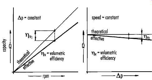
FIG. 52 Dependency of volumetric flow and discharge pressure of reciprocating
plunger pumps. Courtesy of Uraca Pumpenfabrik GmbH & Co KG
The process
As can be imagined, the amount of the supercritical liquid throughput must be exactly maintained, controlled, and monitored. Pressurization of the solvent stream is usually accomplished via a positive displacement plunger type pump, designed to accommodate the extraction medium's physical properties. Plunger pumps are especially adaptable to this application in view of their high discharge pressures and small throughput capacities. As an example, because of the compressibility of liquid CO2, an especially critical necessity is the reduction of the pump's internal clearance volume to achieve optimum volumetric efficiency.
Experience shows that plunger pumps deliver an excellent overall efficiency and thus are highly economical machines to develop the required pressures and capacities. This result is in part attributable to the proportionality of pump speed vs. capacity and its relative indifference to differential pressure. Performance is as illustrated in FIG. 52.
A high pressure supercritical recycle process
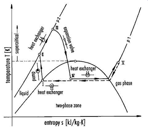
FIG. 53 Temperature-entropy diagram (CO2 extraction process)
FIG. 53 depicts the temperature/entropy curve for a carbon dioxide loop for a typical extraction process. A pump pressurizes the carbon dioxide liquid from I to II (suction pressure P1 to discharge pressure P2). At pressure P2, the carbon dioxide is heated in a heat exchanger from II to III i.e. the process temperature. An extractor is employed to achieve the desired carbon dioxide combination of pressure and temperature and is let down from III to IV. An evaporator is used to proceed from IV to V at which point the heavier product is separated out. The "purified" carbon dioxide proceeds from V to I and is condensed, sub-cooled and at process point I, sent on at P1 to the pump suction.
Potential variations in the pressure, temperature and flow process conditions permit the extraction of diversified substances from various raw materials. Therefore, the process is extremely flexible and lends itself to many potential applications.
Supercritical extraction system Assuming a common raw material, it is also possible to extract selectively several different components (mostly as liquid) as previously indicated. In general, a supercritical extraction system consists of four major components:
- A pump to pressurize the extraction medium
- A pressure vessel (extractor) where the extraction process takes place
- A pressure vessel (separator) where the extract and medium are separated
- Heat exchangers to control the extraction and separation temperatures
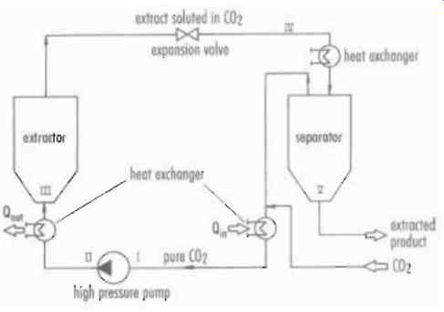
FIG. 54 shows a typical process arrangement for these elements. The Roman
numerals correspond to the entropy diagram in FIG. 53.
Liquid carbon dioxide pump requirements
There are specific requirements for the design of a high pressure pump for use on liquid carbon dioxide. Initially, the pump must be capable of pressurizing the liquid to pressures over the supercritical threshold. Liquid carbon dioxide is extremely compressible as may be seen from the thermodynamic table. There is also the problem that the temperature gain during the pressurizing process is not precisely controllable. As such, especially in large pump applications, there is the question of not being able to accurately predict pump capacity. This problem must be solved through experience and empirical measurement. To understand these pump issues further, a research project was undertaken to explore what happened in the pressurizing chamber of a plunger pump so that this data could be used to further advance the design technology.
The pump was fitted with instrumentation to measure the following: pressure in the space between the suction and discharge valves, inlet and outlet temperatures, cooling medium temperatures and ambient temperature. See FIG. 55.
 FIG. 55.
FIG. 56 shows the developed indicator diagram through the synchronization of the functions in the liquid cavity and plunger stroke. In this diagram, A to B is the suction stroke. B to C is the pressurization to the required discharge pressure; and C to D is the discharge valve opening permitting the liquid carbon dioxide to enter the discharge line.
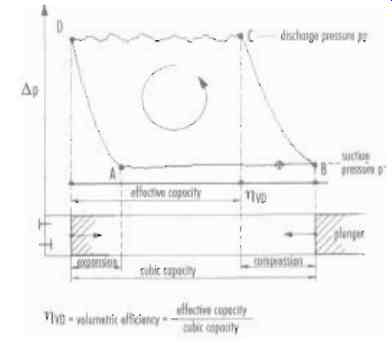
FIG. 56
The relationship of C to D and B to D demonstrates a volumetric efficiency VD, considerably less than that obtained when using water. This is explained by compressibility. D to A shows the expansion of the liquid carbon dioxide remaining in the pump's clearance volume. The cycle is repeated starting at A. Repetitive testing under varying process parameters provided extremely useful empirical data to enable the pump equipment design to supply exactly the required process service conditions. In addition to concerns about the strength of materials, cavitation-free operation is an absolute necessity to maintain trouble-free operation. Also, to maintain a high degree of operational efficiency, the seals on the suction and discharge valves are an important consideration.
Summary
Test results indicate that high pump efficiency may only be obtained by the careful design of the high pressure liquid end to absolutely minimize dead space. Also of interest is the stuffing box sealing system, in the light of liquid carbon dioxide lubrication and cooling characteristics. A method of monitoring the functioning of the seal system is a prime design consideration.
In summary, pumping liquids used in supercritical applications requires especially suitable construction materials and pump design technology (See FIG. 57) based upon practical application and creative research and development.
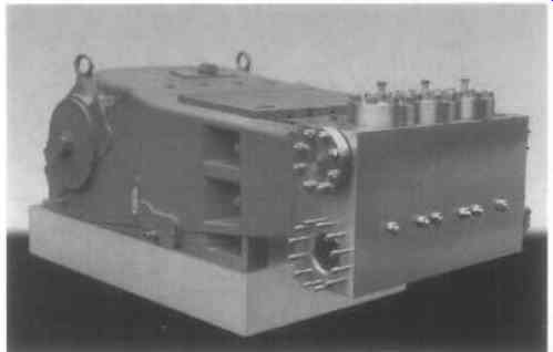
FIG. 57