AMAZON multi-meters discounts AMAZON oscilloscope discounts
11. Submersible sump pumps for construction projects
Introduction
Electrically driven sump pumps are readily available from stock in various sizes from 1 kW up to 20 kW both for sale and leasing. Standard pumps of up to 60 kW can usually be supplied on short delivery from the manufacturer. Pumping of this kind is primarily intended for temporary drainage work for building and construction activities on site. In the case of major construction projects, the installations may be of a permanent nature.
Pumps constructed of aluminum may be restricted to certain water grades.
Types of drainage
The nature of the drainage is characterized by the type of civil engineering activity. Industrial and housing construction does not normally require involvement with rivers or lakes and drainage is therefore mainly concerned with groundwater, storm and rainwater etc. The drainage period is short in relation to the construction period and the pumping requirement is often of a limited nature. Sizes 1 to 5 kW easily meet the requirements.
Harbor and bridge construction works involve their own type of drainage characterized by large flows and moderate to low delivery heads. Discharge pipes can often be short, further limiting the total delivery head. Typical of this type is drainage and drying out of coffer dams. This type of draining is often simple to plan and supervise. Pumps of low head of 10 to 30 kW are required to yield flows of 180 to 600 m^3/h.
The greatest pump investment, in percentage terms of the total costs, is often required by hydro-electric power plant construction works and mining. The investment is particularly large in the case of long deep tunnel sections. Sophisticated dewatering techniques involving severe demands on planning and maintenance are mainly concerned in the case of tunnel driving.
A typical four year power plant construction project illustrates the implications for pump choice.
General plant information
Headrace tunnel 4200 m long, area 24 m^2
Two transport tunnels, each 400 m, area 15 m^2
Tailrace tunnel 5600 m, area 30 m^2
Three transport tunnels, each 350 m, area 15 m^2
Maximum head 62m
Differences in level in the transport tunnels between ground level, open excavation, and lowest level, i.e. at entrance to main tunnel.
Tunnel 1 41m
Tunnel 2 40m
Tunnel 3 34m
Tunnel 4, 5 36m
The transport tunnels are driven at a gradient of 1:10.
Transport tunnel 1 may be used as typical for drainage techniques for tunnels and rock chambers.
Pump sizing data
Total estimated flow of water Qb comprises:
- Estimated leakage of water due to poor rock
- Estimated penetration of melt and rain water through open excavation
- Estimated amount of drilling water
Total difference in elevation levels between lowest water course and discharge pipe outlet = Hstat
Total length of pump pipeline = Ltot, Pipe details: quick-coupling pipes 100mm diameter and 150mm diameter.
Two drilling units are used with a total water requirement of 8.4 m^3/h when in operation. Leakage from the rock is estimated to be 6 m^3/h and melt/rain water to be 12 m^3/h, QD = 26.4 m^3/h. A safety margin added to ensure pumps could always cope with water flow brought the flow to Qmax = 36 m^3/h.
An estimate of the pressure loss in 100 mm and 150 mm pipes respectively with a design flow of 36m^3/h indicates 100 mm pipe to be acceptable. Pressure loss Hf = 9 m. Total differential head:
Hstat + Hf = 41 + 9 = 50 m
The drainage is divided into two phases.
Driving of the tunnel from tunnel face and open excavation to level at -41 m at the main tunnel. During this phase, use is made of pumps capable of pumping full flow but about half the differential head, i.e. 36 m^3/h x 25 m. The intention is that the pump should be light and well-matched to the actual duty.
When about half of the length of the tunnel has been driven, i.e. about 200 m and Hstat = 20.5 m, the first pumping station can be constructed and made permanent for the entire construction phase.
After the transport tunnel has been put to use, water flows from the main tunnel now under construction. Admittedly, the 8.4 m^3/h drilling water from the transport tunnel itself has now been eliminated, but the four units in the main tunnel produce 16.8 m^3/h and this must be added to the leakage from the main tunnel.
A rough estimate indicates that Qb through the transport tunnel will be 42 m^3/h.
This means that: Qb = 42 m^3/h Hstat = 41m
Qmax estimated to be 60 m^3/h Pressure loss
Hf then becomes 20 m for 100mm pipe, which is too high a loss. If the pipe size is changed to 150 mm, Hf at 60 m^3/h will be 4 m. Thus: Hstat + Hf = 41 + 4 = 45 m
This station may be constructed to two designs: a pump chamber blasted out of the rock or a steel pump tank.
The advantage of the steel tank, see FIG. 32, is that it can be easily moved and can therefore follow the advance of the tunnel downwards. This enables the waste pump on the drilling car to work constantly with the same length of hose and delivery head.
On reaching level -20m a complete pumping station is established at that level and an additional similarly equipped station follows the working face down to the beginning of the main tunnel at level -41m.
When the transport tunnel joins up with the main tunnel two options for the continued drainage of the transport tunnel may be considered, FIG. 33.
Option 1 - Retention of two pumping stations each with a total delivery head of 22.5 m and maximum flow of 60 m^3/h.
Option 2 - Installation of one central pumping station at level -41 m, the pumping duty then being 60 m^3/h x 45 m.
Option 1 is preferable because the pump size used permits greater range of application and reduces the risk of water hammer in the case of power failure. The advantage of Option 2 is that inspection can be limited to a single station.
The total pumping requirement for the transport tunnel until the commencement of Phase 2 is shown in FIG. 34.
General installation instructions for drainage
Determination of size may be found by:
- Difference in elevation
- Length of pump pipe
- Flow
The difference in elevation between the liquid surface and the pipe outlet is always known. The length of the pump pipe can always be determined.
The flow of water to be pumped can usually only be estimated and this must be done on the basis of experience. When this has been done, the manufacturer's instructions should be consulted, to calculate the pipe friction loss and this added to the difference in elevation.
Hstat + Hf = Htot
==========
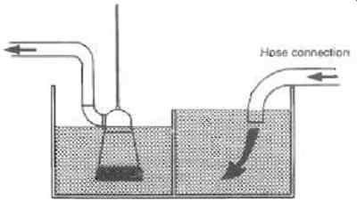
FIG. 32 Pump station m steel tank option Pipe outlet + 0 / -41
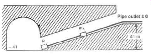
FIG. 33 Drainage with two pumping stations Z3
1. Drilling car with air-powered diaphragm pump
2. Pumping station with submersible electric pump 60 m^3/h x 22.5 m
3. Pumping station with submersible electric pump 60 m^3/h x 22.5 m
4. Submersible electric pump for rain and melt water with its own pipe.
Size about 30 m^3/h x 5 m
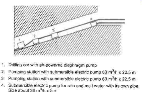
FIG. 34 Drainage with four pumping stations
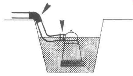
FIG. 35 Correct routing of flexible pipes.
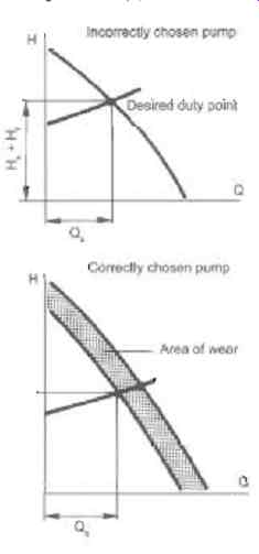
FIG. 36 Pump curves corrected for wear.
=========
Flexible pipes
When using hose as a pump pipe, a 20% addition should be made for unavoidable kinks. Use the shortest possible route.
In open shafts and pits always place the delivery connection at right angles to the pump shaft to avoid kinks.
In the case of sharp edges, e.g. rebates, use pipe bends and connector pipes. See FIG. 35.
Always select a pump giving consideration to the wear factor.
This is especially important in the case of the pumping of tunnels. Drilling waste is very abrasive for impellers and rubber components causing rapid reduction in capacity. See FIG. 36.
12. Use of engine driven self-priming pumps
Pumping unit
FIG. 37 shows a self-priming site pump with a petrol or diesel engine mounted on a skid, and suction hose with strainer.
The discharge hose is normally about 10 m long. Extra lengths can be added when necessary. The skid is fitted with lifting and towing eyes.
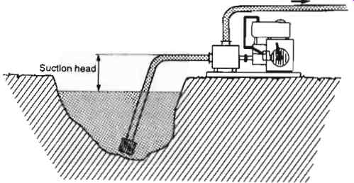
FIG. 37 Skid mounted self-priming pump
Size of pumps
Pumps in good condition can lift 8m. Table 1 indicates the flow ranges of some popular pump sizes at differential heads of between 10 and 20m.
This type of pump can handle solid particles. It is not a solids handling pump in the sense of solid-liquid mixtures but a rugged pump capable of passing occasional, fairly large solids plus mud and soil. The size of the maximum solid increases with pump size. The mesh of the suction strainer is selected on the basis of the pump inner passage size. In practice it is accepted that all solids capable of passing through the strainer are pumpable.
In the case of a discharge hose which is more than about 30m long, it is advisable to check the head drop of the hose. This is easily evaluated with the aid of nomograms. The head drop has the effect of reducing the capacity of the pump.
========
Table 1 Capacities of popular engine driven pumps
Suction connection mm
Flow range m^3 1h 40 10 to 20 50 10 to 30 75 20 to 60 100 30 to 100 150 30 to 300 200 30 to 500
==============
Site installation
Place the pump on a flat, level and if possible rigid pad. Most engines and pumps are splash-lubricated so leveling is quite important. The difference between the water level and the center-line of the suction connection should not exceed 8m. The suction hose should ascend uninterruptedly to the pump. Position the suction strainer near the bottom without burying it in mud, etc. In the case of small flows the strainer can be placed in a shallow pit approximately 0.5 x 0.5 m.
Pumping
Fill the pump with water through the filler. The volume of water necessary is 2 to 5 liters.
Start up and evacuate the suction pipe. If the time for evacuation exceeds 2 to 3 minutes, there is a fault, e.g. too great a suction lift, leaky suction hose, worn-out pump, etc.
As the level in the pit reduces, move the strainer to greater depths. As the suction lift increases the flow will reduce. If there is plenty of water, it is only necessary to check the pump every quarter of an hour. A full fuel tank usually suffices for 2 to 3 hours, but try to avoid running at very low fuel levels. Sediment in the fuel tank can block filters and injectors. If fuel runs out, the fuel system may have to be vented and primed. If the water flow is small, reduce the engine speed to a suitable level.
Each day when pumping is finished, wash the pump and suction strainer out with clean water. Dried mud and setting concrete can seriously affect performance. In cold weather, drain the pump completely each night to prevent freezing. Before storing between jobs, protect in accordance with the manufacturer's instructions.
State when purchasing or hiring:
- Flow and corresponding delivery head
- Suction lift
- Maximum particle size
- Desired power source, e.g. 4-stroke petrol engine
- Maximum weight which can be handled at site
- Maximum noise level
- Requirements for skids or trailers
Pitfalls
- Leaky suction hose results in reduced pump performance.
An air leak on the suction side can be detected by placing the discharge hose under water. Air bubbles indicate air leakage in the suction hose or the pump.
- Petrol-oil mixtures should only be used for two-stroke engines. Wrong fuel causes long delays.
- A blocked suction strainer reduces the capacity of the pump. In such cases check the strainer regularly and clean out as required.
- Kinks in the hoses cause unnecessary throttling.
13. Cargo pumps for tankers
Large tankers for crude oil
Large tankers are fitted with a small number of oil cargo pumps, usually four. The pumps are located in a separate pump room.
The cargo space on board the vessel is divided into 10 to 15 individual tanks. With the aid of a relatively complicated pipe system every individual pump can be used to unload any of the tanks. FIG. 38 shows a simplified diagram of how an oil cargo pump system works.
The suction pipe to every tank is connected to a suction funnel close to the bottom of the tank so that the tank can be completely emptied.
The separator tank, which is connected to a vacuum unit, separates gases drawn into the suction funnel during the final stage of unloading.
The pump is normally driven by a steam turbine, but electric motors can also be used. Due to the risk of fire or explosion due to the gases given off from the crude oil, the pump driver must not be located in the pump room. FIG. 39 illustrates a horizontal shaft pump installation.
The control valve is used to reduce the flow during the final unloading stage, which is necessary to ensure the tank is completely emptied. The valve is automatically controlled by the level in the separator tank.
The non-return valve prevents oil from flowing backwards through the pump when unloading is stopped.
The bulkhead acts as a firewall between the two compartments.
A spacer coupling is used with a mechanical seal to prevent gas leakage.
The pumps are normally sized to unload the vessel completely in about 24 hours. The delivery head required to pump oil to the onshore terminal is 120 to 180m. This results in large pumps with heavy power consumption, up to say 7 MW per pump on the largest vessels. Oil cargo pumps are also used for the loading and unloading of water ballast.
The risk of explosion makes it essential that all equipment capable of generating sparks must be excluded from the pump room and the tank spaces. Pumps should be fitted with mechanical seals, since stuffing boxes can become overheated.
During installation, allowance must be made for the movements which take place in the hull. The shaft coupling should be able to absorb minor misalignments between pump and driver.
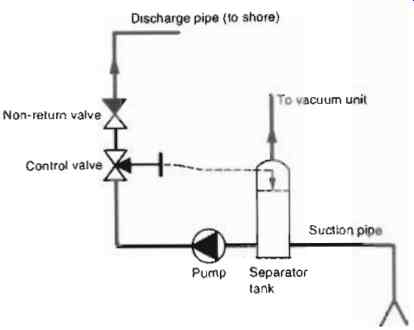
FIG. 38 Simplified cargo pump system
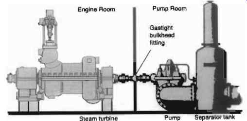
FIG. 39 General arrangement of steam turbine driven cargo pump
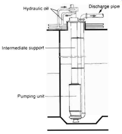
FIG. 40 Hydraulically driven vertical submersible pump
Smaller tankers for finished products
A characteristic of vessels of this type is their ability to transport a great number of different kinds of liquid cargoes. The cargo space in smaller tankers is also divided into small tanks, the number varying in relation to the design and size of the vessel.
As the cargo often consists of a number of different liquids which must not be mixed, a common unloading system cannot be used. Instead every tank is provided with a pump of its own, which, bearing in mind the risk of explosion, should be hydraulically powered. Also, hydraulic equipment can be easier to protect against the ravages of a marine environment. In order to simplify installation, the pumping unit is submersed in the liquid.
The outline drawing in FIG. 40 shows the pump installation in a tank.
The pumping unit consists of a centrifugal pump and a hydraulic motor. The suction connection of the pump is bell-mouthed and its entrance is close to the bottom of the tank. The capacity of the pump is determined by the volume of the tank. The delivery head is 70 to 150 m.
The delivery pipe and intermediate support or column are cross braced to each other to increase rigidity and reduce vibration.
On larger vessels of this kind the distance between the deck and the bottom of the tank is about 15m. In addition to feed and return pipes for hydraulic oil, the intermediate support also contains pipes for sealing liquid.
A constant flow valve maintains the flow of oil to the hydraulic motor, which means that the pump operates at a constant speed independently of the load. The hydraulic motor also contains devices for the remote control of the pump speed. The pumping unit is supplied with hydraulic oil from a power pack which can supply oil to several pumps. The oil pressure in the hydraulic motor feed pipe is normally 160 to 240 barg.
Since the cargo may consist of highly corrosive media, the material of parts in contact with liquids must be given special consideration. The sealing of the pump shaft, which must function in liquids with varying properties, also deserves special attention.
The breakdown of a pump with a tank full of liquid raises difficulties with respect to rapid repair. For such eventualities portable pumps must be available for emptying and flushing out tanks.
LNG carriers
Considerable quantities of LNG are transported from producers to consumers. LNG usually consists mostly of methane so the liquefied gas must be stored at temperatures around -160 degrees at atmospheric pressure. The material requirements for operating at such low temperatures are well known. The main problem with pumping such cold liquids is ensuring the pump unit is cooled sufficiently for the liquid gas to remain liquid.
This problem can be solved by using submerged pumps in the tanks and specially adapted canned motor pumps have been developed. As the complete pump unit is surrounded by the liquid thorough cooling is practically assured. Great care must be taken with the motor connections into its terminal box. Submerged pumps, of the wet pit type have also been used. Double mechanical seals with a suitable barrier liquid, such as propanol or methanol, must be employed.
When spherical storage tanks are mounted on the ship's deck it may not be possible to fit submerged pumps. In these situations, a canned pump built in an external can may be suitable.
The external can must be fitted with vapor vents and liquid level controls to ensure the can is cooled and filled properly.
Adequate insulation must be applied to the suction pipe and the external can to prevent ambient conditions vaporizing the LNG. Very slight temperature rises cause considerable loss of NPSHa.
Pumps for LNG may seem to "rattle" slightly when first started.
This can be due to mild cavitation while vapor is clearing. The "rattling" should stop quite quickly; if not, shut-down and investigate.
14. Detergent manufacturing systems -- pump installations
Introduction
In this example, the finished detergent is manufactured from three raw materials which are mixed in various proportions, depending upon the grade of the finished detergent, before being dispensed into containers of about five or 10 liter capacity. See FIG. 41.
The raw material tanks are elevated above the pumps to provide plenty of NPIPa. Each tank is fitted with a tapered bottom leading to a central connection which is twice the diameter of the pump suction connection. The manual isolating valves are full-bore quarter turn ball valves.
Pumping the raw material
The pumps used are triple lobe pumps operating at low speed to maintain the volumetric efficiency close to unity. All three pumps operate together controlled by the programmable logic controller PLC, as shown in FIG. 42. The speeds of the three pumps are adjusted by the PLC, via variable frequency inverters, to conserve the raw material proportions fed to the mixer. After a preset time the three pumps stop and the electrically actuated valves in the discharge pipes close to prevent "dribbling".
The mixer
Once the mixer has been filled to the required level, the PLC starts the mixer motor which runs for a preset time. The mixer tank also has a tapered bottom and a large connection fitted with a full-bore ball valve.
Finished detergent pump
The finished detergent pump is a low speed triple lobe pump.
Volumetric efficiencies close to unity are assured by adequate NPIPa due to low loss pipework. The pump speed is controlled in response to signals from the dispenser.
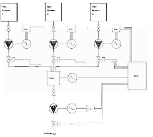
FIG. 41 Schematic of a typical detergent manufacturing system
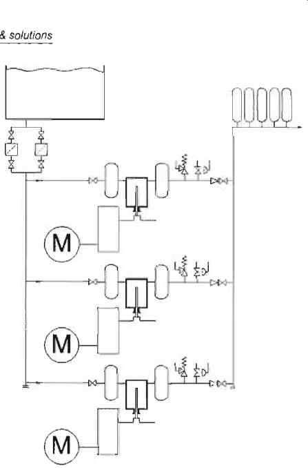
FIG. 42 Schematic of a typical three pump system