AMAZON multi-meters discounts AMAZON oscilloscope discounts
5. Magnetic drive pumps for Chlor-alkali manufacturing --mercury cell processing
Introduction
Chlor-alkali electrolysis is one of the most important processes in the chemical industry and provides the basic chemicals chlorine (CI2), caustic soda (NaOH) and hydrogen (H2). Chlorine and sodium hydroxide are among the top ten chemicals produced in the world.
Important products that contain chlorine or where chlorine is involved in the manufacture are medicines, pigments, pesticides and plastics such as polyurethane, polycarbonate, epoxy resins, silicone and PVC. Chlorine likewise plays an important role in the manufacture of high purity silicon for use in electronics, and in the production of TiO2 for the extraction of white pigments.
Caustic soda is used in large quantities for the treatment of effluent and in the breakdown of bauxite in the manufacture of aluminum. Caustic soda is also needed for the extraction of cellulose, in the production of phenol resin and in the processing of cotton. Another important use of caustic soda is in the manufacture of detergents and soaps.
The hydrogen gained during the electrolysis is of secondary importance.
The mercury cell process
Both chemicals are produced through electrolysis of sodium chloride (salt, NaCl). The mercury cell is one of several industrial processes which use electrolysis to split sodium chloride.
Mercury is of course a very poisonous substance.
Salt brine is introduced into a container (cell) with two electrodes from a DC power source. The carbon anode (negative electrode) is suspended from the top. Mercury flows along the floor of this chamber in the opposite direction. The mercury goes into a chamber underneath, where water flows in the opposite direction. Chlorine is collected from the carbon anode, and sodium is recovered from the cathode. A pump returns the mercury to the top chamber.
A typical cell is approximately 2m wide and 10m long. A plant consists of many cells operating in parallel (see FIG. 18). The mercury cell cathode consists of a slowly flowing layer of mercury across the cell bottom. Sodium/mercury amalgam is produced at the cathode and flows to a separate reactor, known as the decomposer. The amalgam is reacted with water to produce hydrogen gas and caustic soda solution. A 50 % caustic solution is produced directly from the cell.
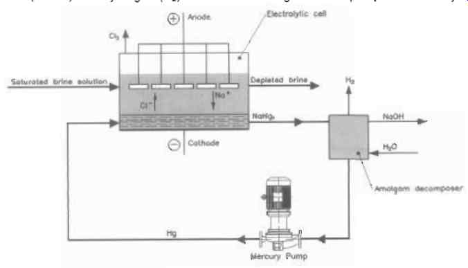
FIG. 18 Mercury cell process schematic. Courtesy of Dickow Pumpen KG
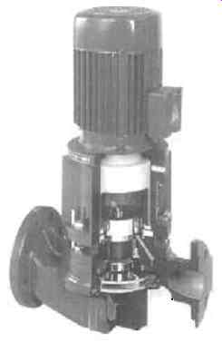
FIG. 19 Section through the magnetic drive pump. Courtesy of Dickow Pumpen
KG
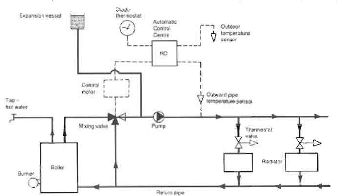
FIG. 20 Boiler and controls for domestic central heating
The pump
When mercury functions as an electrode, it is not consumed in this closed-loop process. Mercury is circulated from the decomposer back to the cell using a centrifugal pump. Several different pump types are used. The pump seal is an obvious leak point for mercury. Early sealless pumps had previously been tried and failed in this severe environment. The flow and head are fairly low, but the fluid weighs 13560 kg/m^3. The first magnetic drive pumps were initially installed in this application in early 1998 and have subsequently overcome many of these problems successfully, (See FIG. 19). Caustic soda produced by this method is of high purity. On the negative side, the toxic nature of mercury is associated with the greatest potential for adverse environmental and health effects.
Strict safety procedures and process controls are followed to prevent workplace exposure and to minimize mercury emissions.
Mercury emissions
Mercury emissions from Chlor-alkali producers have declined significantly over the years. The current contribution of this industry to total natural and anthropogenic mercury emissions is less than 0.1 percent. Western European mercury process plants reduced mercury emissions from 26.60 g/metric tonne in 1977 to 1.25 g/metric tonne in 2000. US producers made a voluntary commitment to the US Environmental Protection Agency to reduce mercury emissions by 50%. Mercury cell use has declined since 1972, and now represents less than 20 percent of all worldwide production. It is claimed that in the future there will be fewer and fewer mercury cells operating as the older plants are shut down or converted to membrane cells. It is also claimed that European and North American producers are committed to not building any new mercury cell facilities.
Magnetic drive pumps are currently used in many mercury cell plants operating in North America.
6. Domestic heating systems and pumps
Introduction
The piping and instrumentation around the boiler of a typical domestic central heating system are shown in FIG. 20. The functions of the constituent components of the system are described.
Boiler
The outlet water temperature from the boiler, set at 90 degrees is controlled by an integral thermostat which switches the burner on and off.
Expansion vessel
The expansion vessel accommodates changes of volume of the water and maintains a suitable static head in the system in order to avoid cavitation.
Pipes
Pipes are sized in accordance with the pressure drop and the length of the runs. Pipes are normally copper but steel and stainless steel are also used on occasions. FIG. 20 shows a double pipe system. Single pipe systems are also used but are more difficult to control.
Radiators
These transfer heat from the hot water to the air in the rooms.
Suitable distribution of water flow to the radiators is ensured by means of adjustable throttle valves. Fitting thermostatic control valves to the radiators removes the need for preset throttle valves.
Hot water for taps
An independent water circuit is shown for heating domestic hot water for taps. In some designs, the hot water heating is controlled by an electrically driven diverter valve which changes the priority between hot water heating and room heating.
Mixing valve
Regulates the system water temperature by admitting return water. Often located close to, or built into, the boiler.
Clock-thermostat
Reduces the system water temperature at night or at other desired times when a lower room temperature is acceptable. This can be used for energy conservation through the day when the house is not occupied or as frost protection.
FIG. 20 Boiler and controls for domestic central heating
Automatic control center
Receives signals from the system water temperature and outdoor temperature sensors. Adjusts the thermal load via the mixing valve by a suitable outward pipeline temperature as a function of the outdoor temperature. In this way a more even room temperature is obtained and a lowering of the room temperature at night is made possible.
Thermostat valves
Valves throttle the flow to radiators depending upon the local air temperature, thereby permitting individual room temperature adjustment. They also make allowance for other heat sources, from the sun, electric sources, etc.
Design temperature
Forward pipe temperature approximately 80 degrees return pipe approximately 60 degrees
At = 20 degrees
The heat required is adjusted in accordance with outdoor temperature.
Pump
The pump circulates a flow which is nearly constant depending upon the pressure drop created by the thermostatic valves and the mixing valve. Pumps can be too large and can cause flow noise. This is avoided by using pumps with built-in flow adjustment by throttling or by-pass or speed control. Wet rotor pumps are often chosen to avoid shaft seals.
Pitfalls
Check the rotation of three phase pumps when installing. The ingress of contaminants from pipes during installation and corrosion products from boiler and pipes causes wear to the pump bearings. The system must be heated up and drained before finally put into operation. The system should be cleaned out regularly with chemical dosing. In the summer when the system is not used, the pump should be run regularly to prevent any sediment collecting and causing possible damage to the pump.
7. Adjustable jet pump
Introduction
Many thousands of adjustable jet pumps have been installed in heating plants, mainly in Europe.
Description
FIG. 21 Cross-sectional arrangement and pressure/velocity distribution for a jet pump
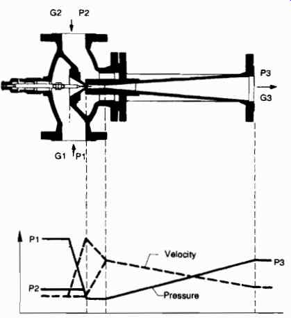
FIG. 21 shows an infinitely variable jet pump with corresponding pressure
and velocity distributions. Regulation is by means of an adjustment needle
valve. In the figure:
G1 = motive mass flow with inlet pressure P1
G2 = pumped mass flow with inlet pressure P2
G3 = G1 + G2 with outlet pressure P3
Two central heating schemes are shown in FIG. 22. When comparing the upper conventional system with the lower using the adjustable jet pump, it can be seen that the jet pump replaces both the mixing valve and the circulation pump. In order to drive the jet pump the necessary pressure must be generated elsewhere. Both plants can be controlled by the outdoor temperature and can be fitted with a timer to provide for reduced indoor temperatures at night.
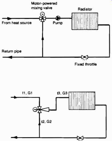
FIG. 22 Central heating schemes -conventional (upper) and with jet pump
(lower)
Regulation
For varying heating requirements caused by variations in outdoor temperature, the setting of the adjustment needle valve is changed. This results in changes in the mixing ratio G2/G1, the temperatures t2 and t3 and the flow G3 through the radiator circuit. In a comparison with the conventional system at reduced heating requirements the result is:
- Lower return pipe temperature
- Reduced flow in the radiator circuit
- Greater temperature difference in t3 and t2
System properties
The reduced flow in the radiator circuit results in reduced pressure drop and thereby in reduced pump energy consumption.
In the case of larger heating systems the necessary pressure for the jet pump is supplied by a centrally located carefully sized centrifugal pump. The adjustable jet pump can in theory replace the circulation pump and the mixing valve in all existing sub-circuits of the heating system.
8. Updating of water supply for industrial use
FIG. 23 shows a schematic arrangement of a water extraction plant feeding a booster station after modification to variable speed control.
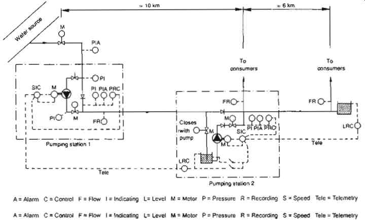
FIG. 23 Schematic arrangement of modernized water supply system
Control before updating
Before modernization both pumps were driven at a constant speed. The flow was controlled by a manual throttle valve, set on the basis of experience, at various times. Variations in water consumption led to varying throttle valve positions and energy wastage. The system could not react to unexpected changes in demand.
Control after updating
After modernization both pumps were driven at variable speeds by thyristor controlled DC motors. The speed of the pump in Pumping station 1 is controlled by the water level in the sump at Pumping station 2. The speed of the pump in Pumping station 2 is controlled by the water level in a storage tower at the end of the main distribution pipeline. Throttling is no longer required.
The speed of the pumps cannot be regulated to zero. In the case of extremely low water demand the pumps are switched off. The storage volumes in the sump and storage tower being adequate to prevent rapid on-off cycling.
Alternative control
In the event of faulty transmission of remote control signals it is possible to control the speed of the pumps in accordance with the pressure on the discharge side of the respective pumps. If Pumping Station 1 is out of service, Pumping Station 2 can be controlled by the level in the sump at the station. If Pumping Station 2 is out of service, Pumping Station 1 can pump directly to the storage tower at slightly lower flow rates.
System details
Installed motor capacity 960 kW per pumping station.
Flow approximately 3400 m^3/h
Diameter of pipelines 800 mm
Operational results after updating
Modernization has resulted in a reduction in water pumping for the industrial plant of about 40%, i.e. water savings of about 2160 m^3/h. The consumption of electricity has been reduced by about 60% corresponding to energy savings of about 10 GWh per year.

FIG. 24 Wet rotor circulation pump, direct coupled in-line version
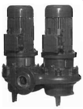
FIG.
25 Circulation pump with standard motor and seal, single and twin head
version
9. Economic aspects of energy utilization
Choice of pumps
When selecting circulation pumps for heating systems, due consideration must be given not only to the relative merits of a particular type of pump, its efficiency and serviceability etc., but also to the overall economy of the heating system as a whole.
Depending upon the size and type of heating system and the relative costs of heating fuel and electrical power sources, it can be shown that, in spite of its lower efficiency, a wet rotor circulation pump can be more economical in terms of total energy costs, than a dry motor pump.
In most instances the final choice of circulation pump depends upon factors other than optimum energy utilization. In small and medium plants it is advantageous to use wet rotor circulation pumps, FIG. 24, since they can, to a large extent, operate without service or maintenance. In large plants, which are often supervised by operating personnel, it is usual to utilize pumps driven by standard motors, dry motor pumps, FIG. 25, because of their higher efficiency.
In borderline cases between small and large plants it may be necessary to carry out a comparative evaluation of the two types. In this comparison the question of total energy utilization should directly influence the choice of pump. The dry pump motor losses are radiated and convected to the surrounding air, whilst the wet pump motor losses are almost entirely given up to the heating system media.
The following describes methods of evaluating the economic aspects related to the use of wet or dry motor pumps respectively two extreme cases.
Definitions and assumptions
When comparing wet rotor and dry motor pumps, it is usual to refer to pump efficiency, qp, which is defined as the relationship between the input and output power, equation 1, the difference in the two values being equal to the pump losses, equation 2.
For pumps, the input energy is defined as the required shaft input power, P, or as the input electrical power supplied from the electric supply system for the pump unit as a whole, the motor losses being also taken into account. The output is usually defined as work done, Pq, equation 3.
The motor efficiency is defined as mechanical power output divided by electrical power output, the difference between the two being mechanical and electrical losses, see equation 4. In close coupled pumps the pump power input and the motor power output must be equal.
The overall efficiency of the pump unit, qu, is obtained by multiplying the motor efficiency, qM by the pump efficiency, qp, equation 5.
All the losses in a pump unit, and even pump work is converted into heat and can be utilized by the heating system. The pump output power, Pq, is dissipated by friction which results in heat.
The pump losses, PvP, are converted into heat within the pump.
If the pump unit is mounted within the heated space, the motor losses, PVM, are given up directly to the surroundings.
In order to make a proper comparison between various types of pump unit, account must be taken of the economic relationship of the heating fuel and the electrical energy supplied to the pump motor. In the following analysis the term "economic efficiency", qE, is used to represent the relationship between the output and input energy, with due consideration to the specific energy costs of the losses.
The cost per heat unit extracted from the fuel, allowing for the efficiency of the heating system, qH, is defined by "a" in equation 6 and the cost for electrical energy supplied by "b" in equation 7, both values in currency/kJ.
Standard motor pump units
FIG. 26 illustrates the energy flow for a pump unit with a standard motor and seal. The motor takes energy from the electric supply system and supplies the pump with mechanical energy via the shaft coupling. The motor energy losses are given up to the surroundings, see equation 4.
The mechanical power is converted into hydraulic energy, equation 3, and the pump losses, equation 8, are converted into heat and transferred to the liquid.
When calculating the "economic efficiency" of a heating system using a "dry" pump unit, then the unit efficiency must include the pump losses, equation 9. The energy costs related to the pump losses being the only losses which can be usefully utilized by the heating system.
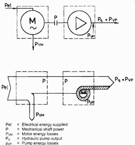
FIG. 26 Energy flow diagram for a standard motor pump unit
Wet rotor motor pump units
FIG. 27 illustrates the energy flow for a pump unit with a wet rotor motor. A large proportion of the energy consumed by the motor is utilized by the heating system.
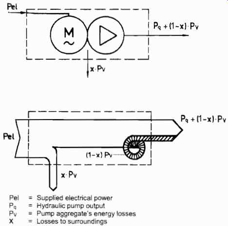
FIG. 27 Energy flow diagram for a wet rotor motor pump unit.
The greater part of the motor heat losses and the pump friction losses are utilized by the plant as additional heat. The heat losses dissipated to the surroundings are negligible and need not, therefore, be included in the calculations. The "economic efficiency" of a wet rotor motor pump unit is obtained by considering the pump unit efficiency and the value of the additional heat supplied, equation 10.
Equations
pump output E power Equ. 1
Tip -pump input power P PvP : pump power input-pump power output. J
[...]
Comparison
Two extreme cases have been chosen to demonstrate the relative differences in total economy when considering similar heating systems.
1. Very low fuel costs and high electricity costs, i.e. the ratio a/b approaching zero.
2. The cost of fuel and the cost of electricity is approximately the same, i.e. the ratio a/b approaching unity.
The expression "economic efficiency", defined previously, is used here to calculate the effect of energy prices and should not be considered as a value of efficiency in the normal sense.
Case 1. In for example, the Netherlands, where gas is relatively cheap and electricity is relatively expensive, the situation is very similar to 1. above.
According to equations 9 and 10 and with a/b = 0 the "economic efficiency" for both dry and wet rotor motor pump units will be equal to the unit efficiency, qu.
Since the unit efficiency for a dry motor pump is always higher than for a wet rotor motor pump, then it follows that the "economic efficiency" for a dry motor pump is always greater than for a wet rotor motor pump, i.e.
1] EDry > 1] EWet
Case 2. In Sweden, for example, electrical energy has been relatively cheap by international standards. The relationship between fuel and electrical energy costs, a/b, is almost unity, if the normal heating system efficiency for larger installations of 0.75 to 0.80 is taken into account. This is very similar to 2.
If a/b is 1, then from equation 9 for dry motor pump units, the "economic efficiency" is equal to the motor efficiency. For wet rotor motor pump units operating under the same conditions, a/b = l-x, where "x" is the losses to the surroundings, then the "economic efficiency" is determined by applying equation 10.
Measurements have shown that the losses "x" to the surroundings are normally between 4 and 7%, for wet rotor pumps with motors up to 2.2 kW, which is less than the corresponding dry motor pump losses of about 20%. It can therefore be concluded that, for heating systems in these circumstances, better running economy will be achieved using wet motor circulation pumps than by using dry motor pumps, i.e.
1~EWet > qE
Conclusions
The heat output of a heating plant is provided by the heat extracted from the fuel and the power supplied to the circulating pump.
The electrical energy contribution, although being relatively small, is important when considering the optimum economy of the complete heating system.
A comparison of heating system energy costs for similar systems in different countries shows that in countries like Sweden where electrical energy is relatively inexpensive, the ratio a/b approaches 1 thus making wet rotor motor circulation pumps, despite their lower efficiency, more economical in service than dry motor pumps.
In countries such as the Netherlands where electricity is more expensive, the ratio a/b approaches 0 and dry motor circulation pumps are more "economically efficient".
10. Pumping of delicate solids food and live fish
Introduction
Screw centrifugal impeller pumps are being used to transport even the most perishable of foods, for example oranges, apples, cranberries, bean sprouts, beans, peas and mushrooms around food processing plants (See FIG. 28). For many years also they have been used in fish farms for the transfer of live fish, grading or tanker-loading duties; helping to reduce and eliminate the damage and high labor costs incurred with the more traditional manual methods previously employed. See FIG. 29.
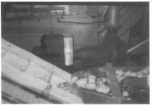
FIG. 28 Food processing of mushrooms. Courtesy of Hidrostal Ltd
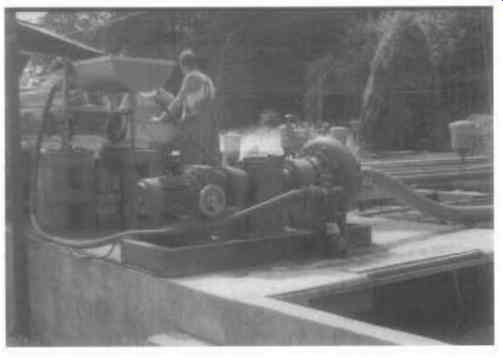
FIG. 29 Handling live trout. Courtesy of Hidrostal Ltd
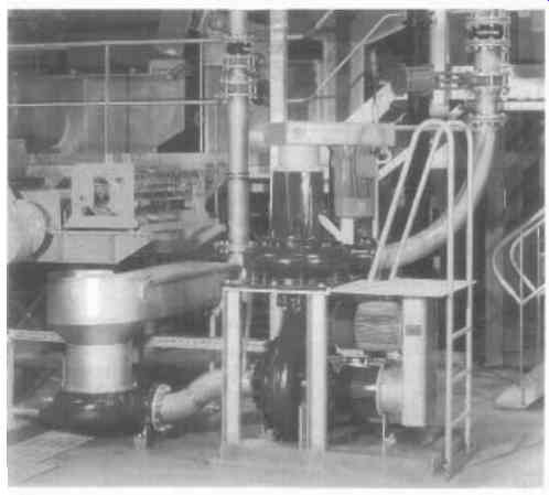
FIG. 30 Typical food processing plant Courtesy of Hidrostal Ltd
Pumping food
The pump and its associated pipework system is particularly beneficial where space is limited or where there is a need to transport large volumes over long distances, or on complicated routes, where the alternative is transferring produce between numbers of different conveyor belts. See FIG. 30. One of the most important requirements of equipment used in food processing is of course, an ability to handle produce gently and this is where screw centrifugal impeller pumps have an advantage, being originally designed to pump live fish. As a consequence, the pump is renowned for its ability to transport even the most delicate of materials without damage.
The pump is characterized by several unique features including an ability to handle delicate solids without damage and viscous materials at a low shear rate. This allows the transportation of even the most fragile materials over a wide range of pumping rates. It has a very smooth hydraulic path, large free passages and high efficiencies which produces low re-circulation of the liquid within the pump. This in turn results in the use of smaller electric motors, lower power costs and reduced maintenance costs.
Cleaning the pump provides minimal disruption to the factory processes; this is achieved by flushing with clean water or pumping a cleaning agent through the pipelines. Because the pump system is easier to clean it is more hygienic. As well as promoting rapid and effective cleaning, the fact that the pipework is enclosed reduces the danger of dirt falling into the system or indeed any produce falling out. This has the double benefit of increased productivity and promotes a safer, cleaner and more pleasant working environment.
Pumping live fish
In this application, pumps are supplied as trolley or skid mounted units, with a variety of drive options. For duties where a suction lift is required the unit is easily primed by use of a fitted high capacity, hand-operated diaphragm pump.
A variable speed drive arrangement is incorporated to ensure that the pump speed/duty can be tailored to enable optimum performance for gentle, damage free handling to be achieved.
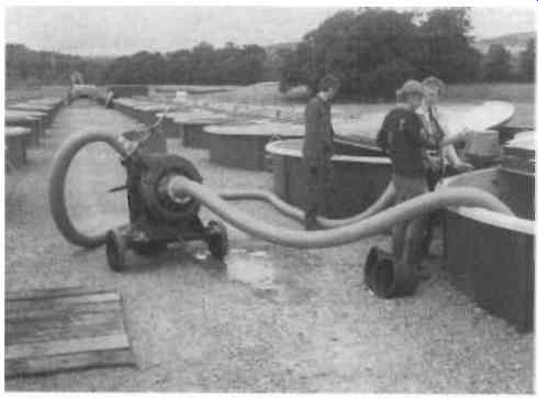
FIG. 31 The pumping of live fish. Courtesy of Hidrostal Ltd
Units can be available in a range of pump sizes and configurations suitable for handling a wide range of fish sizes from fingerlings up to full grown salmon. See FIG. 31.
Prev.: part 1 | Next: part 3
Home Comprehensive
Pumping Manual top of page