AMAZON multi-meters discounts AMAZON oscilloscope discounts
(cont. from part 1)
Welding of Asperities
Wear through the welding of asperities parallels that of the built-up edge. As shown in FIG. 19, the greatest rate of wear by built-up edge occurs at lower cutting velocities or temperatures. A built up edge forms because of high resistance to chip flow along the tool's face, which causes a portion of the chip to shear off as it moves past the tool. This action is most prominent when cutting temperatures are below the recrystallization temperature for the material. Work hardening is retained, and the built-up edge is harder and stronger than the rest of the chip. This same situation exists for wear through the welding of asperities.
The asperities on a tool are brittle and relatively weak in bending or tension. If welding takes place between the chip and the asperities because of the extremely high unit pressures, the work hardened chip material is strong enough to pull these asperities off the tool. However, if the temperature is near or beyond the recrystallization temperature, then the bond between the chip or built-up edge and tool is no weaker than the material adjacent to it, because work hardening has not been retained. Therefore, the rate at which these asperities are pulled out diminishes.
If cutting conditions are such that the resulting temperatures approach or surpass the critical temperature for a given tool material, the reduced resistance of the tool, and the increasing tendency for alloying between work and tool material, cause a high rate of wear and rapid failures. When cutting temperatures are low, the processes of wear by abrasion and welding of asperities become most prominent.
Effects Of Manipulating Factors On Tool Wear
The effects of manipulating factors on tool wear are concerned with either modifications that influence the cutting process directly for a given tool and workpiece material or inherent material properties that resist or promote wear.
For a given tool and workpiece material combination, cutting temperatures are influenced mostly by cutting speed and, to a lesser extent, feed and depth of cut ( FIG. 24). Adjustments in speed or feed, or both, will affect tool wear.
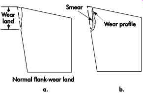
FIG. 23. Section of tool shows the effect of smear and other causes on
flank wear.
It may be possible to use another material that inherently has better temperature-resistant properties to maintain original or even higher production rates with less sensitivity to temperature failure. The cost of the second material may be higher than that of the first, but it may be more than justified by higher production rates at increased operating temperatures.
Changes in tool geometry that result in higher shear angles, less chip distortion, lower frictional resistance, and thinner chips will lower cutting forces and decrease cutting temperatures. They contribute to a reduction in the rate of tool wear for given cutting conditions. Within practical and design limitations, rake, relief, and other angles should be matched to the application providing the most free-cutting strong geometry that directs cutting forces in the workpiece's most rigid section. Heat transfer characteristics also may be adversely affected if the point of the tool is too thin as a result of high relief and rake angles. The heat at the point does not dissipate as rapidly, and higher temperatures prevail.
Workpiece materials with relatively high hardness, shear strength, coefficient of friction, work-hardening capacities, and containing hard constituents promote more rapid wear under certain cutting conditions. Materials such as titanium or stainless steels, which have poor thermal conductivity, do not dissipate heat from the cutting zone as rapidly as other materials, and temperature failures are more common.
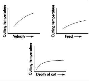
FIG. 24. Relative effects of velocity, feed, and depth of cut on cutting
temperatures for a given work material and tool geometry.
Effect Of Wear On Machinability Criteria
The study of machinability involves certain criteria that play a prominent part in the evaluation of the cutting process. Machinability ratings for a given material are entirely relative in that one material is used as a base. The ratings can vary, not only among the machining processes, but also with the criteria used in the evaluation for a given process. Though much data is available about numerous materials, erroneous conclusions may result if it is not interpreted or applied properly.
Much of the available data, particularly with respect to cutting forces, specific power requirements, and surface quality, is based on the results of investigations performed with sharp tools.
These investigations serve a valuable purpose when analyzing the cutting process and deter mining initial levels of performance. However, they give no indication as to how long the initial level of performance will be maintained when tools begin to wear. Some materials that are given very high machinability ratings with sharp tools are extremely sensitive to tool wear. Performance may drop off rapidly with time. On the other hand, similar materials may have lower initial levels of performance but are less sensitive to tool wear, maintain the original levels for longer periods of time, and actually receive higher production performance ratings.
Another sort of data that warrants some caution in direct application is the tool-life curve.
These curves (see FIG. 25) usually are based on accelerated wear tests. They are plots of cut ting velocity versus cutting time, or cubic inches (millimeters) of metal removal before failure for a given size of cut under otherwise constant cutting conditions. Failure can be identified in several ways. A preselected amount of flank wear (for example, .03 in. [0.8 mm]) may indicate failure in tests with carbide and ceramic tools. Also, the quality of a machined surface may be used to de note failure of any tool material. Whenever wear is used in some form as the criterion of failure, the results can be plotted as a generally accept able straight line on log-log coordinates.
For various reasons (mostly economic), points used to establish the tool-life curve come from comparatively short tool lives, usually less than one hour of cutting time. If the velocity for longer tool life is desired for a practical application, these curves are usually extended and the velocity for the desired tool life is extrapolated as indicated by the dotted line in FIG. 25.
However, this practice can sometimes lead to very unsatisfactory results.
High cutting velocities result in high cutting temperatures. When short tool lives are en countered, the cutting temperature is in or near critical temperature ranges, which promote rapid tool wear by diffusion and chemical decomposition. In this region, small changes in velocity or temperature may have relatively large effects on wear rate and, therefore, tool life. The solid line in FIG. 25 represents a typical plot.
The further the cutting temperature is removed from the critical temperature, the less effective wear by diffusion and chemical decomposition becomes, and wear by abrasion and welding of asperities becomes more prominent. Since the total wear rate decreases at this point, there should be a lesser effect upon tool life for the same incremental change in cutting velocity. The absolute slope of the curve should increase, as represented by the dashed line in FIG. 25. The actual velocity for a specified tool life may be considerably lower than the predicted velocity by extrapolation from a curve based on short time tests. Whether all workpiece and tool materials exhibit this kind of behavior to any predictable degree is not fully known.
There is considerable evidence that accelerated wear tests can give misleading information and care should be taken to make proper use of this information. Some materials are much more sensitive to tool wear than others. The general wear trends are similar, although not to the same degree.
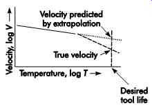
FIG. 25. Tool-life curve showing error that can be introduced in predicting
velocity for longer tool lives by extrapolation of typical accelerated-wear
results (solid line). Lower velocities affect the rate and type of tool wear
to change the slope of the curve. Slopes approaching 0 indicate greater sensitivity
to temperature while slopes approaching 1 indicate the effect of abrasive
wear.
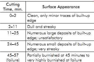
Table 2. Effects of tool wear on surface quality
Numerous changes may take place during the life of a cutting tool. Whether these changes are important depends upon the machining objective. In cutting ductile materials, increases in crater and flank wear literally cause a change in the true tool geometry, which usually affects chip formation. Changes in chip form can be sudden, particularly when the crater starts to break through the cutting edge.
One of the most notable effects of tool wear is the change in surface quality. During a test on AISI 1045 steel at 190 ft/min (57.9 m/min), there were five distinct changes in surface appearance before total tool failure occurred at 57 minutes.
Table 2 lists these changes. The changes in surface quality reflect the unstable character of the cutting edge as wear progresses. With materials that are notorious for formation of built-up edges, surface roughness usually reaches unsatisfactory proportions long before actual cutting tool failure. In the previous example, if surface finish was the criterion of failure, tool life would have been about 11 minutes rather than the 57 minutes of actual cutting time.
Tool wear has a definite effect on cutting forces; the ratio of increase can be beyond expectation. In production operations, feeding or thrust forces can increase to as low as two and as high as 40 times the value for a sharp tool, depending on the type of flank wear encountered.
In one test, the feeding force rose from a sharp tool's value of 11-505 lbf (49-2,246 N) for a flank wear land of .0084 in. (0.213 mm). In another test on a material of the same commercial grade but from another source, the feeding force rose from an initial value of 16 lbf (71 N) to only 180 lbf (801 N) for the same width of wear land. The cutting conditions were exactly the same in each case, but there were sufficient differences in material behavior (even though both materials were within commercial specifications for the grade) to cause flank wear patterns such as those illustrated in FIG. 23a.
On the basis of the condition of the flanks, one might suspect that tangential cutting forces or cutting power would, or should, show the same general characteristics as the feeding forces. Actually, in the tests cited, there was not only comparatively little difference in power requirements for the operation in spite of the large difference in feeding force, but power requirements increased by a factor of only one-half in each case.
Although a large increase in feeding force may not appreciably affect power requirements, the effect on tool or workpiece deflections can be quite pronounced. In the example cited above, the formed diameters increased by .050 in. (1.27 mm) and .028 in. (0.71 mm) respectively, with the higher and lower forces. Because of clearances in machine-tool assemblies, the typical force deflection characteristics of a tool mounted on a slide controlled through a series of links can be represented by the curve shown in FIG. 26.
Initially, a small change in force can result in a rather large deflection. As the play between parts is taken up and elastic resistance increases, a comparable change in force results in a smaller deflection of the tool. Thus, it is apparent that a range of feeding force from a very low to a high value would absorb the greatest deflection range.
If the initial feeding force is high, most of the tool deflection occurs prior to any effects created by tool wear, and the change in dimensions is lower in magnitude.
The previous examples illustrate certain effects of tool wear, but more than that, they illustrate the ever-present variations and difficult-to-explain results that complicate metal cutting practice.
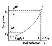
FIG. 26. Effect of forces on machine-tool component deflections.
TOOL LIFE
The types and mechanisms of tool failure have been previously described. It was shown that excessive cutting speeds cause a rapid failure of the cutting edge; thus, the tool can be declared to have had a short life. Other criteria are some times used to evaluate tool life, including:
• change in quality of the machined surface;
• change in the magnitude of the cutting force, resulting in changes in machine and work piece deflections, which lead workpiece dimensions to change;
• change in the cutting temperature; and/or
• costs, including labor, tool, and for tool changing time, etc.
The selection of the correct cutting speed has an important bearing on the economics of any metal-cutting operation. Fortunately, the correct cutting speed can be estimated with reasonable accuracy from tool-life graphs, provided that necessary data are obtainable.
The tool-life graph is shown in FIG. 27.
The logarithm of tool life in minutes is plot ted against the logarithm of cutting speed. The resulting curve is very nearly a straight line in most instances. For practical purposes, it can be considered a straight line. This curve is expressed by the following equation (unless otherwise mentioned, equations and figures that follow are for U.S. customary units only):
VTn = C (eqn 15)
[...]
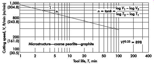
FIG. 27. Tool life versus cutting speed. Tool material-Kennametal carbide,
tool geometry-0, 6, 6, 6, 6, 0, .050, work material-gray cast iron, 195 Bhn.
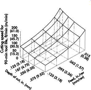
FIG. 28. Effect of feed and depth of cut on cutting speed for 90-min tool
life; workpiece material-gray cast iron, tool material-HSS.
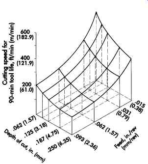
FIG. 29. Effect of feed and depth of cut with in creased cutting speed
for 90-min tool life; workpiece material-gray cast iron, tool material-HSS.
(coming soon) Table 3. Numerical values for K1
(coming soon) Table 4. Correction factors for compositions of tool material
(coming soon) Table 5. Numerical values for d0.37 and f 0.77
GUIDELINES FOR CUTTING TOOL DESIGN
The design of cutting tools is not a pure science involving only computations to be carried out in functional isolation. Of itself, a cutting tool is only a piece of metal of special shape and construction, although frequently it is a very expensive piece of metal.
Good tool design is accomplished with consideration of many inseparably related factors: the composition, hardness, condition, and shape of the workpiece material; rate and volume of the specified production; type, motions, power, and speed of the machine tool to be used; toolholders and workholders available or to be designed; specified accuracy and surface of the finished workpiece; and many other factors, common or specific to the particular operation. The following discussion is, therefore, very much the business of the good tool designer. He or she cannot escape responsibility by saying that some of the factors leading to undue tool wear, or to tool failure, are the responsibility of the process or methods functions. The designer should know, or anticipate, possible application difficulties that lie ahead for the tool about to be designed and then accommodate the difficulties through the design or consult with the other manufacturing functions as to changing certain conditions, or both.
Rigidity
Setup rigidity is vital to maintaining dimensional accuracy of the cut surface since the tool shifts into or out of the cut with the accumulation of static deflections and take-up of loose fits.
Rigidity also maintains surface-finish quality, avoiding the marks made by elastic vibration and free play of loose fits and backlash. In the control of vibration, rigidity of the part and cut ting tool can make the difference between success and failure of the machining operation.
Increasing mass reduces vibration amplitude and resonant frequency, while dampening reduces amplitude by dissipating vibratory energy as frictional heat. Since each part of the cutting system (in other words, the machine, fixture, tool, and workpiece) can affect the mode and amount of vibration, most should be made oversize and broadly supported. This provides design latitude for those members having higher cost and space limitations. Designers should be generous with rigidity, anticipating fast, efficient cuts.
Strength
The strength of each member can be considered separately and related to the magnitude and application of force it will transmit. When the operation is performed correctly, each member should be sufficiently strong to prevent breakage or deformation beyond its elastic limit. The de signer also must consider overloads and damage that may be encountered, providing abundant strength wherever economically possible. In particular, generous size and material specification should give good working life to areas subject to abrasive wear and work hardening under impact loads. But chatter, packed chips, or binding due to setup misalignment can multiply normal operating forces many times. Moreover, tool failure, mechanical malfunctions, and operating errors threaten destructive casualties, even with costly over-design.
Weak Links
A common practice is to protect the structural chain with weak links in anticipation of casualties to confine or limit the possible dam age. Suitable low strength with high rigidity is illustrated by the common soft shear pin. But these weak links must be strong enough to with stand normal operation and overload if possible.
Permanent members are made unquestionably stronger in comparison and protected by location. Identical design criteria make weak links an ideal combination with wearing details. They should be comparatively cheap, with duplicates widely stocked or readily produced, and provide easy, accurate replacement mounting. Mass produced, delicate workpieces are natural weak links, though cutting-tool inserts are the typical wear and breakaway members. Indexable insert cutting tools, using replaceable backing seats, are ideal examples of wear and damage protection.
Force Limitations
Operating forces obviously may be limited by a weak-link member, as in the case of a delicate workpiece. A machine tool, such as a hydraulic stroke planer or broaching machine, may be related in terms of force, with the ratings under stated but subject to measurement and control.
Some saws, mills, and grinders regulate feeding force instead of cutting force in the direction of cutting velocity. This causes the machine to stop feeding if an accident occurs, or if forces begin to exceed a safe level.
Speed, Feed, and Size
A machine tool's speed and feed ranges, cutting tool adaptor capacity, and working clearance put restrictions on the tool design and production rate. The effect of forces is indirect but inevitable. A milling cutter with few teeth contacting a delicate workpiece exerts only a few times the cutting forces of one tooth, while high speed permits rapid completion of the cut. Limited cutter diameter and a low speed range would require more teeth and more force or a longer cutting time. Variable infeed rates can be used to speed rough stock removal and then minimize distortion while finishing, as in the case of a grinding wheel spark-out. The important thing is to design around limitations and take full advantage of flexibility.
Related Force Components
Total cutting force usually is resolved into three mutually perpendicular components:
1. force in the feeding direction,
2. radial force, and
3. tangential force, FT.
Force in the feeding direction of a turning, boring, facing, plunge forming, or parting tool corresponds to radial force on a peripheral-cutting milling cutter tooth or abrasive wheel or belt con tact area. It is commonly taken with one-fourth and up to three-fourths of the tangential force, FT, for sharp tools, the larger fraction being appropriate for extremely heavy feeds. Straight-line cutting tools, namely saw-blade teeth or broaches and planer or shaper tools, develop this force component in the direction of feed into the work. The radial force component for turning or boring tools is normal to the finished work surface in facing, planing, and shaping, and in an axial direction for peripheral milling. It may be negative, pulling into the work as a result of large positive back rake, but it is usually a pushing force of relatively low value. The most significant force component is the tangential force FT, which acts on the top of the tool tangent to the direction of rotation of the part or tool. Carbide turning tools typically have 1,000 lbf (4,448 N) of tangential force in general-purpose machining applications.
Chip Disposal
One sure way to overload a cutting tooth is to block the path of the chip flowing across its face so that the chip is recut. Single-point tools cutting ductile work frequently employ a pressed-in chip breaker to curl an otherwise stringy chip so that it will break in the form of a figure nine and fall away. If the groove design is too weak for the size of cut being taken, it can cause edge chipping or breakage. Small-diameter, coarse-pitch milling cutters commonly have ample chip spaces, pro vided the chips are thrown or washed out between successive passes through the cut. On the other hand, large-diameter cutters taking full-width cuts must carry the chip a half rotation before it can exit. These cuts require large chip slots. It is difficult to remove work materials like soft steel or copper alloys and titanium, whose chips tend to weld onto the tool face. Chip disposal in milling slots may demand high positive rake angles and climb milling instead of conventional cutter rotation to eject the chips. Complex selection and application methods have been developed for tap ping and deep-hole drilling where chip clogging, misalignment, and runout can readily break tools.
A good tool design should provide space for chip flow and a means of disposal, which may well be the solution to many problems.
Uneven Motions
Another sure way to overload a cutting tooth is to increase the feed rate beyond its structural or chip-disposal capacity. The machine's structural deflection accomplishes this in the example of a drill breaking as it moves through the work.
As the heavy thrust of the chisel edge is relieved, structural members spring back toward their un stressed shape, and the drill lips plunge into the work for an oversize bite. Feed mechanisms may employ air or hydraulic fluid, whose compression is elastic, or gearing and a lead screw nut fit may introduce backlash. Machine way motion becomes jumpy at slow speeds (slip-stick motion), even with heavy lubrication. A milling cutter at slow feed may actually rub until pressure builds up.
It then may dig into the work and surge ahead.
Adding to the difficulty, the sudden change in cut ting torque adds to the pounding caused by teeth entering the cut.
Torsional vibration and backlash tend to develop in a rotary drive train. Should cutter rotation become so erratic that it momentarily stops, carbide teeth will generally break at once by being bumped into the work. With some teeth gone, the entire cutter may fail progressively as each successive tooth is unable to carry the extra load left by the damaged teeth.
Chatter
The rapid, elastic vibration that sometimes appears between the tool and work is easily detected by marks on the work surface and by the sound that gives it the name "chatter." Chatter occurs from the momentary separation of the tool and workpiece and the immediate banging back into contact at an audible frequency. It is a danger signal of the impending possibility of chipping or fracture. The remedy is to eliminate uneven motion and loose fits.
Chatter is less likely with few teeth moving at high velocity taking thick chip loads, and with high rake and ample relief angles. A negative rake angle may prevent pulling into the cut. Changing the speed of the cutter or piece part (rotation or translation), just by a small percentage, can reduce chatter. In grinding, harder action or broader contact helps withstand bumping. As an extreme simplification, chatter can be combated with lower cutting forces, while looseness and backlash cannot. Like all other problems in machining, chatter can be greatly reduced by proper tool design.
SINGLE-POINT TOOLS
Single-point tools have one cutting edge. They are used for operations such as turning, boring, shaping, and threading.
Basic Tool Angles
The tool signature or nomenclature for a single-point tool is a sequence of alpha and numeric characters representing the various angles, significant dimensions, special features, and size of the nose radius. This method of identification has been standardized by the American National Standards Institute (ANSI) for carbide and HSS, and is illustrated in FIG. 30, together with the elements that make up the tool signature.
Back-rake Angle
The back-rake angle is between the face of the tool and a line parallel to the base of the toolholder. It is measured in a plane parallel to the side-cutting edge and perpendicular to the base. Variations in the back-rake angle affect the direction of chip flow and cutting force. As this angle is increased while other conditions remain constant, tool life will increase slightly and the required cutting force will decrease.
Cutting-edge strength decreases dramatically as positive back-rake angles are increased above 5°. Similarly, cutting-edge strength increases as back rake becomes negative and is optimized at around -5°.
Side-rake Angle
The side-rake angle is defined as the angle between the tool face and a plane parallel to the tool base. It is measured in a plane perpendicular to both the base of the holder and side-cutting edge.
Variations in this angle have the largest effect on cutting force and, to some extent, affect direction of chip flow. As the angle is increased, forces are reduced about 1% for each degree of positive side rake and less tearing of the workpiece occurs.
Negative side rake increases edge strength and is recommended for most steels.
End-Relief Angle
The end-relief angle is between the end flank and a line perpendicular to the base of the tool.
The purpose of this angle is to prevent rubbing between the workpiece and the end flank of the tool. An excessive clearance or relief angle reduces the strength of the tool, so the angle should not be larger than necessary; it is typically in the 5-7° range.
Side-relief Angle
The side-relief angle is between the side flank of the tool and a line drawn perpendicular to the base. Comments regarding end-relief angles are applicable to side clearance or relief angles as well. For turning operations, the side-relief angle must be large enough to prevent the tool from advancing into the workpiece before the material is machined away. Angles of 5-7° are sufficient for a feed ratio under .03 in. (0.8 mm) per revolution. Threading of low-pitch threads requires up to 25° clearance.
End-Cutting-Edge Angle
The end-cutting-edge angle is between the edge on the end of the tool and a plane perpendicular to the side of the tool shank. The purpose of the angle is to avoid rubbing between the edge of the tool and the workpiece. As with end-relief angles, excessive end-cutting-edge angles reduce tool strength with no added benefit.
Lead Angle (Side-cutting-edge Angle)
The lead angle is between the straight cutting edge on the side of the tool and the side of the tool shank. This side edge provides the major cutting action and should be kept as sharp as possible. Increasing the lead angle tends to widen and thin the chip, and influences the direction of chip flow. An increase in the side-cutting-edge angle reduces the chip thickness for a given feed by a factor of the cosine of the angle. This, in effect, reduces the chip contact width to thin out the built-up edge. An excessive side-cutting-edge angle redirects feed forces in the radial direction, which may cause chatter. As the angle is increased from 0 to 45°, workpiece entry is moved away from the vulnerable tip (radius) of the tool to a stronger, more fully supported part of the tool, usually resulting in increased tool life.
However, these benefits usually will be lost if chatter occurs, so an optimum maximum angle should be sought.
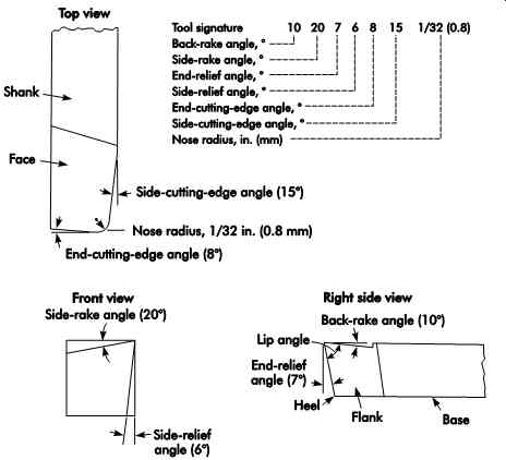
FIG. 30. A straight-shank, right-cut, single-point tool, illustrating the
elements of the tool signature as designated by ANSI. Positive rake angles
are shown.
Nose Radius
The nose radius connects the side- and end cutting edges and dramatically affects tool life, radial force, and surface finish. Sharp, pointed tools have a nose radius of zero. Increasing the nose radius from zero avoids high heat concentration at a sharp point. Improvements in tool life and surface finish usually result as the nose radius is increased up to .06 in. (1.6 mm). An increase in nose radius has the same general effect as increasing the side-cutting-edge angle.
The shape of the contact area changes, but at the point of contact between the machined surface and tool, the chip is very thin. In comparison, the feed marks and resultant surface finish are much smoother than those left by a sharp nosed tool. There is, however, a limit to radius size that must be considered. Chatter and poor surface finish will result if the nose radius is too large; an optimum maximum value should be sought. There is a correlation between ideal surface roughness, nose radius, and feed, which is given by:
(eqn 19) where:
Ra = surface roughness, ?in. (mm)
f = feed, in. (mm)
re = nose radius, in. (mm)
Tool Signature
A comparison of Figures 30 and 31 illustrates the difference between a right- and left-hand tool. Right-hand tools are the most popular.
Tables 6, 7, and 8 (coming soon) give the recommended angles for single-point tools of HSS, carbide, and cast alloys, respectively.
Chip groove
Chip grooves can be ground into the cutting surface of HSS and brazed carbide tools. Table 9 shows the typical dimensions used. Press technology has made the need to hand-grind car bide tools obsolete because indexable inserts have the grooves pressed in. Pressed-in chip grooves provide for chip control and force reductions with unique grooves designed for specific applications.
Rapid advances in chip-groove design are the result of research into the effects of changes in groove geometry. FIG. 32 illustrates examples of standard chip-groove geometries.
forces and power requirements The following is an example of how the equations for power given earlier are applied to turning. A steel part, shown in FIG. 33, is to be machined between centers in a lathe equipped with an air-operated tailstock spindle. The maxi mum depth of cut is to be .100 in. (2.54 mm), the feed is .010 in./rev (0.25 mm/rev), and the cutting speed is 300 ft/min (1.5 m/sec). The cutting-tool geometry is 10, 10, 6, 6, 10, 15, .030. The feeding force is assumed to be two-thirds of the tangential cutting force. The following equation applies to this material.
FT = cf0.8 d (eqn 20) where:
FT = tangential cutting force, lbf (kN)
c = constant of proportionality
f = feed, in./rev (mm/rev)
d = depth of cut, in. (mm)
Calculate the diameter, Dc, of the air cylinder required to hold the work between centers against the cutting forces if the minimum pres sure in the air cylinder may reach 60 psi (414 kPa). Both centers rotate; thus the friction between the work and the centers need not be considered.
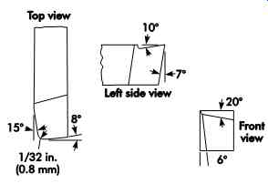
FIG. 31. A left-cut tool. All other aspects are identical to FIG. 30.
(coming soon) Table 6. Recommended angles for high-speed steel, single-point tools
(coming soon) Table 7. Recommended angles for carbide, single-point tools
(coming soon) Table 8. Recommended angles for cast alloy single-point tools
(coming soon) Table 9. Dimensions for parallel- and angular-type chip breakers, in. (mm)
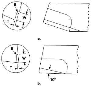
FIG. 32. Chip grooves ground into tools.
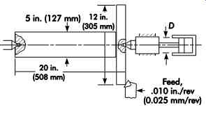
FIG. 33. Steel part in a turning operation.
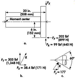
FIG. 34. Forces in turning operations.
where:
R = resolved force, lbf (N)
FT = tangential cutting force, lbf (N) Resolving R about the tailstock center ( FIG. 34c):
where:
Fy = force in y, lbf (N)
Dc = diameter of air cylinder required to hold the work, in. (mm)
MULTIPLE-POINT CUTTING TOOLS
Multiple-point cutting tools comprise a series of single-point tools mounted in or integral with a holder or body and operated in such a manner that all the teeth (tools) follow essentially the same path across the workpiece. The cutting edges may be straight or in the form of various contours to be reproduced on the workpiece. Multiple-point tools may be either linear travel or rotary. With linear travel tools, the relative motion between the tool and workpiece is along a straight-line path. The teeth of rotary cutting tools revolve about the tool axis. The relative motion between the workpiece and a rotary cutting tool may be either axial or in a plane normal to the tool axis. In some cases, a combination of the two motions is used. Certain form-generating tools involve a combination of linear travel and rotary motions.
Figures 35 and 36 illustrate two types of milling cutters and indicate the difference in nomenclature between their angles and single-point tools. FIG. 36 shows the peripheral cutting edge angle as 0°, with positive and negative directions indicated.
Whether a cutting tool is single-point or one component of a milling cutter, various angles must provide the most efficient cutting action.
Theoretical considerations may dictate larger angles, but actual cutting experience may dictate smaller angles for greater tool strength without chatter. Advantages from increasing any angle always must be considered together with its effect on tool strength.
Cutting Processes
Cutting processes for multiple-point tools are similar to those for single-point tools. Linear travel tools produce a series of chips similar to those produced by single-point tools on planing cuts. Milling cutters produce chips that vary in thickness because of the nature of the tooth path, as illustrated in FIG. 37. The chips produced by axial-feed tools tend to be conical because varying diameters across the cutting edge cause different portions of the cutting edge to travel discrete distances. Aside from these differences, studies have shown no fundamental difference between the metal-formation processes involved in forming chips using these tools or single-point tools on turning or planing cuts.
Design Considerations
The single most important factor affecting the performance of any cutting tool is the attainment of a high degree of rigidity in the entire machining system. This includes the cutting tool, machine tool, fixture, and workpiece. A lack of rigidity in any of the system's elements can largely nullify the benefits of high rigidity in other elements. This interrelationship is all too often overlooked by fixture designers-work pieces are not adequately supported at the point of cutting.
FIG. 35. A solid plain milling cutter showing the basic tooth angles and
the tooth land.
With adequate workpiece support and ma chine-tool rigidity, an increase in the rigidity of the cutting tool can enable large improvements to tool life. Such improvements are particularly evident in the case of the super-strength alloys used in aircraft and missile production. When drilling such alloys, improvements in tool life by a factor of 50 or more have been obtained by using short, heavy web drills in place of conventional drills.
When designing multiple-point tools, there must always be some compromise with maxi mum rigidity. Most multiple-point tools are required to carry the chips generated for some distance before they can be ejected. Adequate chip space must be provided to avoid jamming, which can cause tool breakage. The amount and shape of the chip space provided depend on the material and the nature of the cut. If the chips are discontinuous, less chip room is required and closer tooth spacing can be used. More chip room and wider tooth spacing are required for high-tensile continuous chips. With some tools, it is possible to incorporate some form of chip breaker on the cutting face to produce smaller chips and thus improve the chip-conveying ability of the tool.
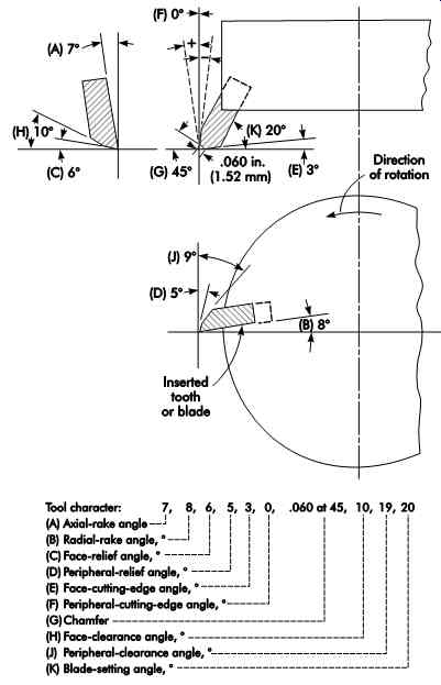
FIG. 36. A face milling cutter with inserted teeth. All pertinent tooth
angles are included.
With tools such as milling cutters and broaches, tooth spacing can also affect the smoothness of operation and accuracy of work. If too many teeth are in contact with the work at the same time, the tool part or machine may be overloaded. Over loading may cause breakage of the tool or driving key. And, the deflection due to the increase in loading may cause a decrease in accuracy. With milling cutters it is generally desirable that at least one tooth be in contact with the work at all times. This keeps the tool and workpiece under load at all times, avoiding the vibration that occurs from varying shock loads.
The rake and relief angles on multiple-point cutting tools affect both the tool performance and tooth strength. High rake angles usually make cutting freer and more efficient. High relief angles reduce the rubbing that occurs on the flank of the tool. These angles, however, cannot be increased without limit. As either the rake or the relief angle is increased, cutting-edge strength is reduced. In addition, while high relief angles reduce the temperature resulting from flank friction, they do cause a greater change in workpiece size for the development of a wear land of a given size. The selection of rake and relief angles, therefore, requires a compromise.
Operating Considerations
In setting up the operating conditions for any multiple-point cutting tool, there are three important variables that can be adjusted:
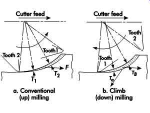
FIG. 37. A comparison of undeformed chip shapes.
1. feed per cutting edge,
2. cutting speed, and
3. cutting fluid.
Of these, the feed per cutting edge is the most important and should be established first.