AMAZON multi-meters discounts AMAZON oscilloscope discounts
(cont. from part 2 )
Feed per Cutting Edge
With some tools, such as taps and broaches, the feed per tooth is determined by the design of the tool and can be changed only by tool modification. With most other tools, the feed is determined by selecting an appropriate machine setting. It has long been demonstrated that it is more efficient to remove metal in the form of thick chips rather than thin ones, so the maximum possible feed per tooth should be used. However, the maximum feed per tooth is limited by the following factors: cutting-edge strength; rigidity, and allowable deflection; the surface finish required; and tool chip space.
The feed cannot be increased without limit be cause some point will be reached at which either the tool or machine will be overloaded. Overload can cause breakage, either immediately or with the accumulative increase in cutting forces due to dulling. As the feed is increased, the cutting forces increase, causing greater deflection between the tool and workpiece. Deflection can become so large that it is impossible to hold the accuracy required. The surface finish produced on the workpiece usually deteriorates as the feed is increased. This may necessitate the use of light feeds. With some metals, the greater volume of chips produced with heavy feeds may overload the chip space in the tool. In other cases, heavier feeds will produce broken chips that can be handled more easily than continuous chips resulting from light feeds.
In peripheral milling, the actual chip thickness is affected by the depth of cut. Maximum undeformed chip thickness equal to the feed per tooth is obtained when the width of cut equals one half the cutter diameter. With shallow finishing cuts, the maximum undeformed chip thickness is much less than the cutter advance per tooth.
In the extreme case of peripheral milling, with a shallow width of cut, the undeformed chip thickness may be so low that there is no chip load, which causes the tool to burnish or work harden the material rather than cut it. To prevent this on shallow cuts, feed rates of three to four times the normal should be used.
Cutting Speed
After the maximum allowable feed has been established, the cutting speed should be considered. At a constant feed per tooth, there is relatively little change in cutting forces as the cutting speed is increased. In the normal operating range, speed has relatively little effect on surface finish, but sometimes a large increase of speed (usually made possible by a change of tool material) will yield an improvement in surface finish by increasing the temperature to a point that the workpiece is softened, resulting in less tearing. The principal effect of increasing cutting speed is to produce parts faster at a constant feed per tooth. This increase in production normally justifies the tool-life reduction resulting from operating at higher temperatures. The optimum cutting speed is what will permit parts production at the lowest cost per piece. This requires analysis of all the costs, including machining, tool changing, and cutting-tool acquisition and maintenance costs.
Cutting Fluids
Use of the correct cutting fluid can substantially improve a machining operation. The proper cutting fluid can permit higher feeds and increased speeds, as well as contribute to attaining better surface finishes. Cutting fluids should be directed to the exact point where the cutting is being done and be applied in a constant, even flow. No machining operation should be set up without some consideration of cutting fluids.
Dry or minimal quantity lubrication machining is a consideration, however, to minimize cleanup and environmental considerations, such as waste disposal. Correct operating parameters, cutting tool design, and cutting material selection (including coatings) are critical for making dry or minimal quantity lubrication machining work.
Further, their applicability depends greatly on the workpiece material.
Forces And Power Requirements
Knowledge of cutting forces is essential to machine and fixture design, and for the determination of power requirements. Force and power predictions for multiple-point tools are more complex than those for a single-point tool.
Varying numbers of teeth may be in contact with the work, chip size can vary in different parts of the cut, and orientation of the cutting teeth may not be constant with respect to the workpiece. The best methods to determine forces on such tools are by actual measurement on the machine to be used or in a simulated setup in a metal-cutting laboratory. Since such measurements are sometimes inconvenient or impossible to make, methods for making reasonable force and power estimates may be of value.
One approach is to consider the multiple-point tool equivalent as a series of single-point tools, then estimate the contribution of each tool and sum these to arrive at the resultant forces. The following methods of calculation are preferable.
When it is not possible to estimate forces and power directly, a fairly good estimate still can be made by considering the cutting energy. The removal of 1 in. 3 (164 mm^3 ) of an alloy steel with a hardness of about 200 Bhn at normal feeds requires the expenditure of about 56,492 J (15.7 Wh) of energy. In terms of engineering units, this can be stated as 1.25 hp/in.^3 /min. Thus, if the maximum rate of metal removal is computed in terms of cubic inches per minute, this value can be multiplied by 1.25 to give a reasonable estimate of the horsepower required at the cutting tool.
For SI metric conversion:
Unit horsepower = (hp/in. 3 /min) × 2.73
= unit power (kW/mm3 /sec)
If a rotary tool is involved, the tool torque, M, in inch-pounds (Newton/meters [N/m]), can be estimated from the following equation:
(eqn. 21)
where:
M = tool torque, in.-lb (N/m)
hp = tool horsepower
N = rotational speed of tool, rpm To convert to SI units:
M × 0.11298 = Newton/meter (N/m)
In the case of linear-travel tools, the force in the cutting direction can be estimated from the following equation:
(coming soon eqn-22) where:
F = cutting force, lbf
hp = tool horsepower
V = cutting speed, ft/min To convert to SI units:
F × 4.448 = Newtons (N)
Equations 21 and 22 must be applied with caution, since they will be useful in estimating torque or cutting force only if an accurate estimate of the maximum rate of metal removal is made. If they are applied to the average rate of metal removal, they will indicate only average torque or average force. This could be considerably below the peak forces in the case of intermittent cutting, as might be encountered in milling or broaching. Further, all of the equations presented ignore the even higher peak forces resulting from impact or vibration during cut ting. Because of these limitations, the equations should not be used as a basis for the design of critical elements in the machine or fixtures.
LINEAR-TRAVEL TOOLS
Tools traveling in straight-line motions are referred to as linear-travel tools. These tools can be used in high-production applications where close tolerance work is being performed. They normally produce good surface finishes and are versatile and economical.
Broaches
The most common multiple-point, linear travel tool is the broach. Broaches are used for producing either external or internal surfaces.
The surfaces produced may be flat, circular, or of an intricate profile, as viewed in a section normal to tool travel. A broach is essentially a series of single-point tools following each other in the axial direction along a tool body or holder. Successive teeth vary in size or shape in such a manner that each following tooth will cut a chip of the proper thickness. The basic elements of broach construction are illustrated in FIG. 38.
The spacing and shape of broach teeth are determined by the length of the workpiece and the chip thickness per tooth, as well as by the type of chips formed. The chip space between the broach teeth must be sufficient to take care of the volume of chips generated. Broach teeth are provided with rake and relief angles in the same manner as other cutting tools. Standard broaching nomenclature designates the rake angle as the face angle and the relief clearance as the back-off angle. Rake angles fall in the same range used for other tools, but back-off angles normally are quite low, in the range of between 0.5° and 3.5°. Low back-off angles are used on broaches to minimize the loss of size in re-sharpening. Final finishing teeth are often provided with an unrelieved land behind the cutting edge to ensure proper sizing of the workpiece. Some times non-cutting burnishing teeth follow the final cutting teeth.
Internal broaches ( FIG. 39) are either pulled or pushed through the work. Strength considerations limit the design of such broaches.
Surface broaches ( FIG. 40) ordinarily are carried on a large, guided ram; here, strength is not as critical since the cutting tool can be transferred to the ram at many points along the broach length.
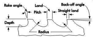
FIG. 38. Basic elements of broach construction.
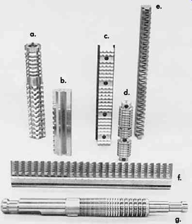
FIG. 39. Typical broaches: (a) special form broach; (b) titanium slotting
broach for compressor disks; (c) semifinish rock-gear form broach; (d) round
broach used for half-round operation on connecting rods; (e) titanium dovetail
roughing broach for compressor disks; (f) Inconel pine-tree finish broach
for turbine disks; (g) rebroach for hardened gears.
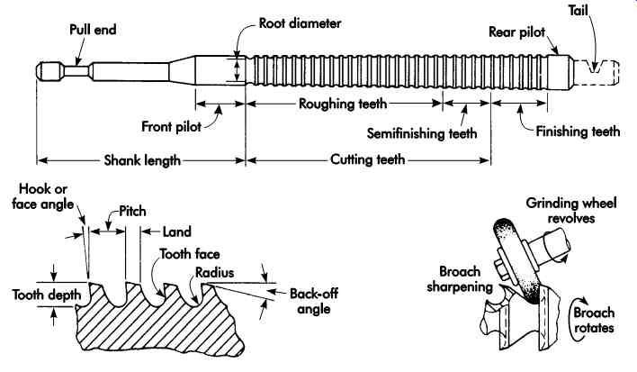
FIG. 40. Hole broach details.
Broaches are commonly made of HSS as solid units, but carbide-tipped and inserted-blade broaches are sometimes economical. This is particularly true in the case of surface broaches, which are better adapted to mounting carbide indexable inserts. Broaches can be used to cut helical internal forms if the broaching machine is equipped to rotate the broach at the proper lead rate as it passes through the work.
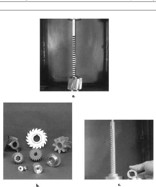
FIG. 41. (a) Broaching with keyway sets or individual keyway broaches;
(b) broaching with production keyway broaches; and (c) broaching with internal
hole broaches.
Standard Push Broaching
When broaching with keyway sets or individual keyway broaches (see FIG. 41a), bushings are required. Shims are required with all but the smallest broaches, and are provided with each individual keyway broach and broach set for cutting to standard depth. The procedure for broaching with keyway sets or individual keyway broaches is as follows:
1. Select the right bushing for the bore (sizes are plainly marked) and insert in the bore of work.
2. Insert broach (which is also plainly marked for size) for the desired width of the keyway into the bushing slot and check alignment.
3. Place this assembly in the press.
4. Lubricate.
5. Push broach through.
6. Clean broach.
7. Insert shims as required to obtain the exact keyway depth.
No shims are necessary when broaching with one-pass keyway broaches (see FIG. 41b), but bushings are required. The procedure is:
1. Insert bushing in part.
2. Insert broach and check alignment.
3. Lubricate.
4. Push broach through.
5. Clean broach.
When broaching with production keyway broaches, no shims or bushings are required (see FIG. 41c). The following procedure should be followed:
1. Insert broach pilot into bore of part.
2. Lubricate.
3. Push broach through.
4. Clean broach.
Similarly, shims or bushings are not required when broaching round, square, hexagon, and special shapes with internal hole broaches. The following steps apply to internal hole broaching:
1. Insert broach and check alignment.
2. Lubricate.
3. Push broach through.
4. Clean broach.
Here are some additional items to consider:
• Always use proper ram speed to prevent chatter marks and edge wear.
• Properly drilled pilot holes are essential for a true and clean cut.
• Never use a dull or poorly sharpened drill to make pilot holes.
Figures 42a and b show ram adapters, or rear guides, which provide support and guidance for the broach at the shank end, minimizing the possibility of deflection or breakage. Ram adapters are recommended for all standard round and oval broaches, for square and hexagon broaches .25 in. (6.4 mm) and smaller, and in certain other situations where an extraordinarily high degree of accuracy is required.
If the ram adapter is used as a rear guide for the broach, the hole in the ram adapter must be in alignment with the pilot hole in the workpiece.
Whenever ram adapters are used, they must provide a tight, true fit to both the press ram and to the broach shank.
Most broaching failures (poor finish, drifting, deflection, breakage, chatter marks, or edge wear) can be attributed to deficiencies in alignment, lubrication, broach sharpness, tooth configuration or design, material hardness, and incorrect broaching speed or pressure. Here are some basic tips:
• Two or more workpieces may be stacked to establish the minimum length of cut. When using keyway broaches, make sure that the cut does not exceed the standard length of the appropriate bushing. And, when broaching any hole, be sure that at least two teeth are engaged at all times.
• Maintain a rigid setup at all times. The workpiece must be solidly fixed or nested perfectly square with the base plate and ram face. Check to make sure that all square and parallel surfaces on the face of the ram and the base plate remain true.
• Proper alignment of the broach, workpiece, and ram is the most important factor in all broaching operations. Misalignment can cause drifting, deflection, and even breakage. If a keyway broach drifts, consider reversing the workpiece or turning the broach so its teeth face toward the back of the press. Another approach is to let the bushing protrude above the workpiece to give more support to the back of the broach, thereby helping to keep it aligned. If a collared bushing is used, place it upside down under the workpiece. The broach should be centered under the ram at the beginning of the cut. If it moves out of alignment after starting to cut, back off the pressure on the ram and align the broach itself. This should be repeated during successive cuts to ensure perfectly straight cuts.
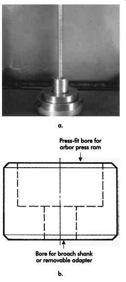
FIG. 42. (a) Ram adapter, (b) Ram adapter to guide broach shank.
• When working with iron and steel, use the standard broach as supplied. Never attempt to broach any material harder than Rockwell C35. If using brass or free-machining bronze, remove the rake and stone a slight land on the crest of the teeth to prevent drifting.
• Broach lubrication is vital for achieving longer broach life and a cleaner finish. To reduce friction, always lubricate the back of keyway broaches, regardless of the material to be cut. Various materials require different lubricants. For mild steel, a good quality cut ting oil or water-soluble coolant brushed on the teeth is recommended. For tough steels such as nickel alloys, it is recommended to use a good grade of sulfur-based cutting oil.
Brass is usually broached dry, but bronzes are worked better with an oil or soluble oil.
Cast iron is almost always broached dry, but the back of the broach should be oiled.
Straight kerosene may be used, but special lubricants are available.
• Always keep broaches sharp. Dull or poorly sharpened broaches will cause drifting, break age, and damage to the teeth. Correct sharpening (see FIG. 43) ensures satisfactory production in terms of time efficiency, conformance to specifications, and finish. While adequate sharpness is determined by the material being broached and the tolerances and finish required, the following conditions typically indicate the need for resharpening: poor finish, tears, lands, galling, etc. on the part; cutting edges show signs of turning; broach teeth are dull to the touch; broached surfaces are too hot at the end of the stroke; broaching pressure is increasing excessively, as indicated by a gage; nicks, gouges, etc., appear on the teeth from improper handling; broach is sticking in the workpiece; and/or the hole is gaging undersize.
Gear-Shaper Cutters
A gear-shaper cutter is a tool that looks, to some extent, like a gear, with the teeth relieved to provide cutting edges. Typical gear-shaper cutters are illustrated in FIG. 44. Gear-shaper cutters are reciprocated in the axial direction, but at the same time are rotated in timed relation ship to the gear being generated. The rotational speed is low compared to the speed of reciprocation, so the shaper-cutter principally is a linear travel tool. The feed per tooth is determined by the rate at which the cutter is fed to depth in the gear blank, and to some extent by the speed of rotation. Gear-shaper cutters, within limits, can be designed for forms other than gears, such as splines, sprockets, etc.
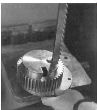
FIG. 43. Broach sharpening.
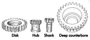
FIG. 44. Standard gear-shaper cutters.
AXIAL-FEED ROTARY TOOLS
Tools that feed into a workpiece while either the tool or workpiece is rotating are considered axial-feed rotary tools. These tools are old but are still some of the most widely used in machining processes.
Drills And Related Tools
The production, enlargement, or recontouring of a hole takes place in drilling and its related processes. Either a rotating cutter and fixed workpiece, or a rotating workpiece and fixed cutter, can be used to produce a chip that is formed and removed from the workpiece.
Twist Drills
In its most basic form, a twist drill ( FIG. 45) is made from a round bar of tool material.
It has a pair of helical flutes that form the cut ting surfaces and act as chip conveyors. Relief is provided behind the two cutting edges or lips.
The intersection of the two relief surfaces across the web between the two flutes is known as the chisel edge. The lands between the flutes are cut away to a narrow margin to reduce the area of contact between the lands and the wall of the hole and/or guide bushing. The metal cut away forms the margin known as the body diameter clearance.
The chisel edge of an ordinary drill indents as it is forced into the metal and, as it turns, it partially cuts like a cutting tool with a large negative rake angle as depicted in FIG. 46. The chisel edge does not penetrate like a sharp point and tends to make a drill start off center. Some drills are ground to reduce or eliminate the chisel edge; among a number of forms are the thinned point, crankshaft grind, and spiral point. Too much compensation may weaken the point, but optimum amounts have been found to reduce thrust force by one-third, increase tool life by as much as three times, and improve hole location precision when compared to the full chisel edge.
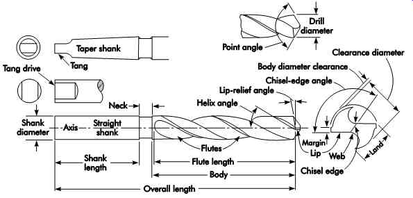
FIG. 45. Nomenclature for twist drills.
The cutting edges illustrated in FIG. 46 correspond to the cutting edges of a single-point tool. An average value for the helix angle is 30°, but angles from about 18° for hard materials to 45° for soft materials are used. The effective rake angle at the edge is larger at the periphery than toward the center of the drill. Some users grind drills at the end of the flutes to create a uniform rake angle along the edges.
The heel of the drill point must be backed off when ground to give relief behind the cutting edges, like the relief on a single-point tool.
Twist drills can be provided with a variety of shanks, but the straight shank and the Morse taper shank are most common. Twist drills ordinarily are made of HSS, but certain sizes and types are available in solid carbide or with car bide cutting tips. Indexable carbide insert drills greatly improve metal removal rates for drilling holes from 1-3 in. (25.4-76.2 mm) in diameter.
Standard drills are available in a wide variety of designs; a few are shown in FIG. 47, which may be used for various materials and services.
The most common variations are the helix angle and web thickness. Tough materials usually re quire the use of rigid drills with heavy webs and reduced helix angles. Free-machining materials can be cut with drills having higher helix angles and lighter webs, which provide more efficient cutting and better chip ejection.
Reamers and Core Drills
Twist drills produce holes; core drills and reamers are hole-enlarging and finishing tools.
The cutting ends of these tools have relieved chamfers that extend to a small enough diameter to permit their entry into the hole being enlarged or finished.
Core drills are designed principally to enlarge existing holes, and provide a greater degree of accuracy and better finish than a two-fluted twist drill.
These tools usually have three or four moderately deep helical flutes. The lands between the flutes are given body diameter clearance to produce a margin similar to that on a twist drill. Typical core drills are shown in FIG. 47. Core drills are usually made of HSS, but in some sizes they can be furnished with carbide tips. Sometimes they are made of a two-piece construction so that only the cutting end needs to be replaced.
Reamers are designed principally for hole sizing where only a moderate amount of stock is to be removed from the hole walls. The stock is removed by a larger number of flutes than are common with drills. Reamed holes usually have superior accuracy and finish. Because of the greater number of flutes and cutting edges, the margins on reamers are much narrower than those on twist drills and core drills, which minimizes galling of the margins. Reamers have little or no starting taper, which improves their ability to accept guidance from bushings. The flutes on reamers may be either straight or helical, depending on the type of work to be finished.
Solid, HSS construction of reamers is most common, but carbide-tipped and solid carbide reamers are available in certain sizes and styles. FIG. 48 shows various commercial types of reamers.
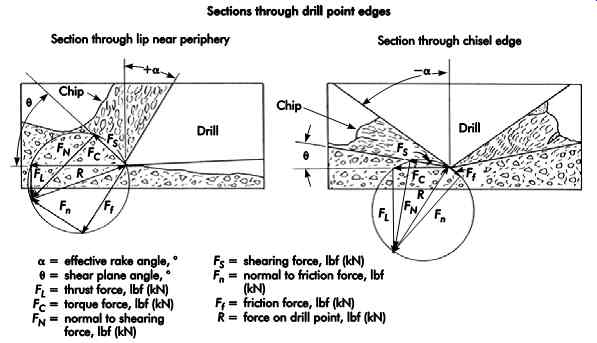
FIG. 46. Sketches made from photomicrographs of chip formation at the two
cutting zones of a twist drill.
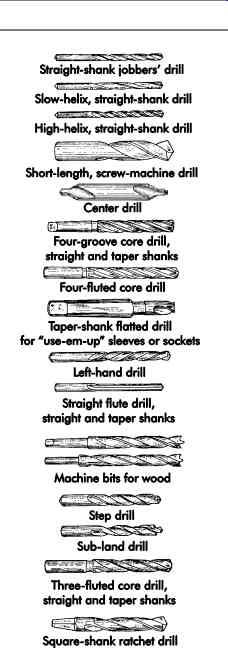
FIG. 47. Conventional and special-purpose drills.
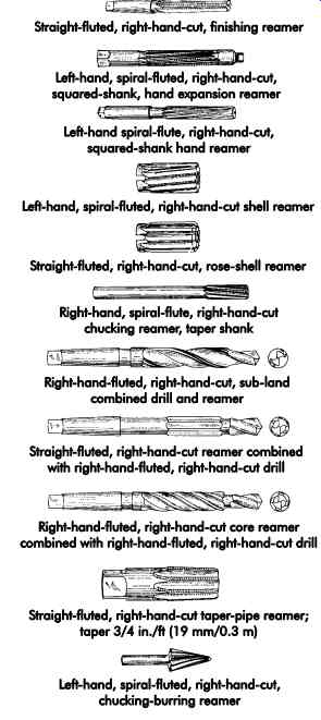
FIG. 48. Commercial types of reamers.
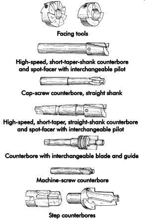
FIG. 49. Types of counterbores and spot-facers.
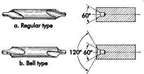
FIG. 50. Combined drills and countersinks.
Counterbores and Countersinks
Counterbores and countersinks are tools for modifying the ends of holes. They are often provided with pilots that engage the existing hole to improve alignment, and are commonly used to provide a seat in a plane normal to the hole axis. When the seating surface is flat and relatively shallow, tools called spot-facers are often used. Deeper seats, such as those used for recessing the heads of socket-head cap screws, are called counterbores. FIG. 49 illustrates various counterbores and spot-facers.
When a conical seat is required at the end of a hole, the operation is known as countersinking and the tools are called countersinks. Such seats are required to receive machine centers and per mit the use of flat-headed screws with the heads flush to the drilled surface.
Except for the angle of the cutting edges, counterbores, spot-facers, and countersinks are similar in construction. They are commonly made with two or more flutes, which usually have a right-hand helix. The flutes are usually shorter than those on drills because the seats produced are relatively shallow. When pilots are provided, they may be either integral with the tool or removable. The tools themselves often are made quite short and used as readily replaceable tips in a holder mounted in the machine spindle. In some cases, one holder will drive a fairly wide range of cutter sizes.
The combined drill and countersink is a specialized tool used for producing countersunk holes for flush-head fasteners and the center holes required for lathe and other machine centers. This tool combines a short two-fluted drill with a two-fluted countersink so the entire drilling and countersinking operation can be performed in one pass on a single setup. Such tools are often made in double end construction as shown in FIG. 50. When one end becomes dull, the tool can be reversed in the chuck to provide another cutting end.
Multiple-diameter Tools
Multiple-diameter holes can be produced or finished in a single operation. Common situations involve drilling and counterboring or drilling and chamfering a hole on the same setup. In high production operations, this can result in lower machining costs.
The simplest way to make a multiple-diameter tool is to start with a tool of the size that will pro duce the largest diameter and then grind down the cutting end of the tool to the size required for the small diameter. The cutting portions of the tool are provided with appropriate relief. This is known as step construction.
Another style of multiple-diameter tool em ploys what is known as sub-land construction.
With a multiple-diameter tool, separate tool lands are provided for each cutting diameter. Small-diameter lands run between large-diameter lands.
Sub-land tools are more expensive because additional manufacturing operations are required to produce the added cutting surfaces.
Step and sub-land drills are included in FIG. 47. Multiple-diameter reamers ( FIG. 48) and counterbores ( FIG. 49) also are commercially available. Where the length of the small diameter portion of the tool is relatively long in terms of the usable tool length, the simpler step construction usually is preferred. Besides lower acquisition costs, such tools provide more chip space in the flutes.
The use of sub-land tools may be advantageous where the small-diameter step is relatively short.
In step construction, the usable sharpening life is limited to something less than the length of the small-diameter step. After this is used up, it is necessary to cut off the tool and completely remanufacture the step end. In sub-land construction, the two diameters can be sharpened for the entire length of the tool and the length of the step is not critical. The restricted flute space due to the presence of the additional lands sometimes limits the depth of hole to which the tool may be applied. With multiple diameters, it is important that the difference in diameters be relatively small. With a large difference in diameter, it is not possible to maintain optimum cutting speeds on both diameters, and there is some difficulty in maintaining adequate strength in the tool.
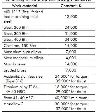
Table 10. Work material factor, K, for drilling with a sharp drill
Power Requirements for Drilling and Reaming
For rotary axial-feed tools, such as twist drills, core drills, and reamers, reasonably accurate estimates of forces and power can be made through the use of tried-and-true formulae developed some time ago.
The torque and thrust for a twist drill operating in an alloy steel with a hardness of 200 Bhn can be represented by the following formulae:
[...]
The constant k is necessary since, for a given feed per revolution, the number of flutes affects the feed per tooth. It has been pointed out that it is more efficient to remove metal in the form of thick chips than thin ones, so tools with a large number of flutes will require proportionately more energy because of the thinner chips they produce.
Whereas the thrust forces can be substantial and thus can have a large influence on the required strength and rigidity, the power required in feeding the tool axially is very small (less than 2% of the total power requirements) and can usually be disregarded. The cutting power is a function of the torque and rotational speed and can be computed by:
(eqn-27) P MN c = 63 025,
(coming soon) Table 11. Values of k for different numbers of flutes*
To convert to SI units:
Pc × 746 = watt (W)
In using these formulae for estimating purposes, an allowance of at least 25% should be made for increases due to tool dulling and further allowances for the efficiency of the machine's drive train. For other materials, the cutting forces vary in about the same ratio as noted for single point tools.
Taps
A tap essentially is a screw fluted to form cutting edges. The cutting end of the tap has a relieved chamfer that forms the cutting edges and permits entry to an untapped hole.
If succeeding chamfered teeth are followed along the thread helix, it will be seen that the effect of the chamfer is to make each tooth have a slightly larger major diameter than the preceding one. Thus, the major feed involved in tapping is a radial feed, although the feed is built into the tool rather than controlled by the machine. This is the case with most other rotary tools. The actual feed per tooth depends on the chamfer angle and the number of flutes. A reduction in the chamfer angle or an increase in the number of flutes will reduce the feed per tooth.
The most common type of tap is the straight fluted hand tap ( FIG. 51). This tap has a straight shank with a driving square at the shank end. In spite of their hand-tap designation, they are generally used in tapping machines. Hand taps are usually available with three different chamfer lengths of nominally 1.25-, 4-, and 8 thread pitches, which are designated respectively as bottoming, plug, and taper taps. Taps also are available with helical flutes and other modifications to suit them to specific applications. Most taps used in production operations are made of HSS. Some solid carbide and carbide-tipped taps are used on work materials with high abrasiveness or hardness. However, these taps are more susceptible to breakage or chipping.
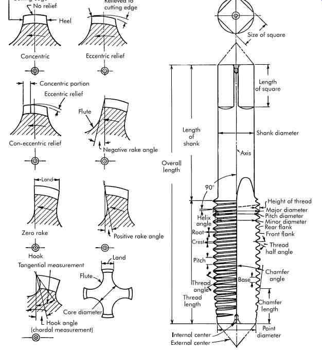
FIG. 51. Tap nomenclature.
====
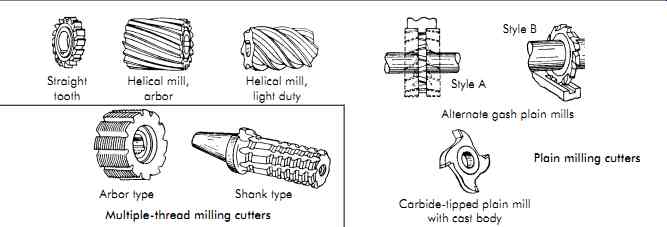
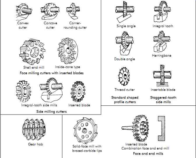
FIG. 52. Common types of milling cutters.
Fig. 42 parts: Straight tooth Helical mill, arbor Helical mill, light duty Arbor type Multiple-thread milling cutters Shank type Convex cutter Concave cutter Corner- rounding cutter Shell-end mill Inside-cone type Face milling cutters with inserted blades Integral-tooth side mills Inserted blade Side milling cutters Gear hob Solid-face mill with brazed-carbide tips Style B Style A Alternate gash plain mills Plain milling cutters Carbide-tipped plain mill with cast body Single angle Integral tooth Double angle Herringbone Thread cutter Insertable blade Standard shaped profile cutters Staggered-tooth side mills Inserted blade Combination face and end mill Face and end mills
====
Milling Cutters
Milling cutters are cylindrical cutting tools with cutting teeth spaced around the periphery (see FIG. 52). FIG. 35 showed the basic tooth angles of a solid plain milling cutter. A workpiece is traversed under the cutter in such a manner that the feed of the workpiece is measured in a plane perpendicular to the cutter axis. The workpiece is plunged radially into the cutter, and sometimes there is an axial feed of the cutter as well, which results in a generated surface on the workpiece.
Milling-cutter teeth intermittently engage the workpiece, and chip thickness is determined by the motion of the workpiece, number of teeth in the cutter, rotational speed of the cutter, cutter lead angle, and overhang of the cutter on the workpiece.
There are two modes of operation for milling cutters. In conventional (up) milling, the workpiece motion opposes the rotation of the cutter ( FIG. 53a), while in climb (down) milling, the rotational and feed motions are in the same direction ( FIG. 53b). Climb milling is preferred wherever it can be used, since it provides a more favorable metal-cutting action and generally yields a better surface finish. Climb milling requires more rigid equipment, and there must be no looseness in the workpiece feeding mechanism since the cutter will tend to pull the workpiece.
Indexable milling cutters have precision pressed or ground-carbide inserts positioned around the cutter body. They are held in by screws, pins, or wedges that can be released for indexing. Some milling cutters may either have profile-sharpened or form-relieved teeth. Profile sharpened cutters are sharpened on the relief surface using a conventional cutter-grinding machine. Form-relieved cutters are made with uniform radial relief behind the cutting edge.
They are sharpened by grinding the face of the teeth. The profile style provides greater flexibility in adjusting relief angles for the job to be done, but it is necessary to reproduce any form on the cutter during each resharpening. In the form relieved style, the relief angle cannot be changed since it is fixed in the manufacture of the cutter.
However, the form-relieved construction is well adapted to cutters with intricate profiles since the profile is not changed by resharpening.
Most large milling cutters are provided with an axial hole for mounting an adapter or arbor, and usually have a drive-key slot. Certain small-diameter cutters, and some cutters for specialized applications, are made using an integral shank construction where the cutting section is at the end of a straight or tapered shank that fits into the machine-tool spindle or adapter. Also, some large facing cutters are designed to mount directly on the machine-tool spindle nose.
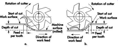
FIG. 53. (a) "Out-cut," "conventional," or "up" milling;
also called "feeding against the cutter." (b) "In-cut," "climb," or "down" milling;
also called "feeding with the cutter."
Number of Teeth in a Milling Cutter
The relationship between the number of teeth and the feed and speed may be expressed as:
(eqn-28) where:
n = number of teeth
F = feed rate, in./min (mm/min)
Ft = feed per tooth, in. (mm) (chip thickness)
N = cutter speed, rpm Equation 29 has been found satisfactory for HSS cutters such as plain, side, and end mills for both production and general-purpose use:
(eqn-29) where:
R = cutter radius, in. (mm) Example: For a 4-in. (101.6-mm) diameter cutter:
Equation 30 was developed for calculating the number of teeth (n) when using carbide tipped cutters (Cincinnati Milling Machine Co. 1951). Since it involves power available at the n F FN t = nR =- 195 58. .
n = -= 195 2 58 218 . . . or 22 teeth
[...]
...cutter, it is helpful in permitting full utilization of available power without overloading the motor ( U.S. customary units only).
(eqn-30) where:
K = constant related to the workpiece material. It may be given the values of 0.650 for average steel, 1.5 for cast iron, and 2.5 for aluminum (these values are conservative, taking into account the dulling of the cutter in service).
Pc = horsepower available at cutter
d = depth of cut, in.
w = width of cut, in.
Power Requirements For Milling
Milling machines, like other machine tools, are not 100% efficient. That is, it takes more horse power (kW) than that required at the cutting tool to run the milling machine in a machining operation. The reason is due to frictional losses, gear-train inefficiencies, spindle speeds that are too high for the particular machine, mechanical condition, etc. Consequently, the power required for milling must include machine power losses and power actually used at the cutter. Efficient use of power at the cutter is influenced by cutter speed, design, cutting-edge geometry, and workpiece material.
Using the power equations given earlier, the total horsepower required at the cutter (Pc) can be calculated. For example, an alloy steel having a hardness of 250 Bhn is to be machined in a milling machine. The depth of cut is to be .250 in. (6.35 mm), the feed is .005 in. (0.13 mm) per tooth, and the cutting speed is 300 ft/min (91.4 m/min). The milling cutter has 12 teeth and is 10 in. (254 mm) in diameter. The width of the cut is 5 in. (127 mm). The specific power consumption is .70 hp/in.3 /min.
Assume:
Pt = 0.5 and E = 0.8
= 8.05, so use a 10-hp motor.
where:
Wp = specific power consumption, hp
V = cutter speed, ft/min
D = tool diameter, in. (mm)
n = number of teeth
f = feed, in./rev (mm/rev)
Pt = power required to operate machine at
no-load capacity, hp (kW)
E = efficiency of power
Pg = motor power required, hp (kW)
The total horsepower required at the cutter (Pc) also is given by the equation,
(eqn-32) where:
Pc = horsepower at the cutter
MR = metal removal rate, in. 3/min
K = factor reflecting the efficiency of the metal-cutting operation To convert to SI units:
Pc × 746 = watt (W)
The K factor varies with the type and hardness of the material, and feed per tooth, increasing as the chip thickness increases. Time-consuming trials are required to determine the quantities involved, because in each case the K factor rep resents a particular rate of metal removal and not a general or average rate.
To make available a quick approximation of the total power requirements, a milling-machine selector table has been devised ( Table 12), which estimates the metal removed for the rated power of various machines under constant load conditions.
(coming soon) Table 12. Milling-machine selector
(coming soon) Table 13. Value of K factor for various materials ( U.S. customary units)
The metal removal rates in Table 12 may be considered products of the K factor (see Table 13). All K constants given are for dull cutters; hence no allowance for increase in power due to dulling needs to be made. All values apply to aver age milling speeds and rake angles recommended for the various materials, and .010 in. (0.25 mm) feed per tooth.
End Mills
End mills are shank-type milling cutters usually designed with some form of relieved end teeth (see FIG. 54). This construction enables them to do some end cutting, but the majority of the cutting takes place on the periphery. Indexable end mills generally use radius corner inserts, but can be furnished with parallel land wiper inserts for generating finishes down to 50 ?in. (1 ?m). End mills are usually considered to be in a separate category from other milling cutters.
High-speed-steel end mills have helical flutes with a flute helix angle between 20° and 40°. Flutes are usually several diameters long, but longer and shorter designs are available. Tools with two and four flutes are most common- larger sizes are available with more flutes. The relieved end teeth permit their use in keywaying or pocketing operations with minimal contact of the surface at the bottom of the recess. Most two flute end mills have end teeth that extend from the periphery to the center of the tool. This permits their use as drills to sink into depth before starting a cut. Some four-flute end mills are made with two diametrically opposed teeth cutting to the tool center. The corners at the intersection of the peripheral and end teeth can be provided with radii to minimize the formation of stress risers in the work. When this radius becomes equal to the cutter radius, the end mill is said to have a ball end. Such tools are widely used to form recesses and cavities in dies. An operation of this sort often is called die sinking.
====
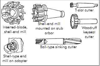
FIG. 54. End mills.
Inserted-blade, shell-end mill Shell-end mill mounted on stub arbor T-slot cutter Woodruff keyseat cutter Shell-type end mill on adapter Ball-type sinking cutter
====
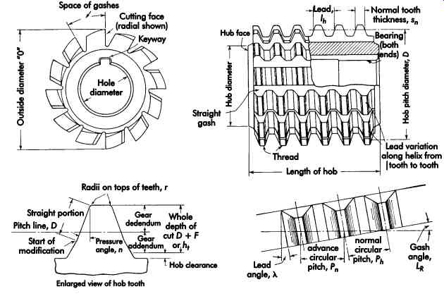
FIG. 55. Nomenclature of hobs.
Hobs
A hob is a generating, rotary cutting tool with its teeth arranged along a helical thread (see FIG. 55). The hob and workpiece are rotated in timed relationship to each other, while the hob is fed axially or tangentially across or radially into the workpiece ( FIG. 56). The cutting edges of the hob teeth lie in a helicoid, which usually is conjugate to the form produced on the workpiece. The teeth on a hob resemble those on a form-relieved milling cutter in that they are designed to be sharpened on the rake face. Most hobs are designed for generating gear teeth or splines. Certain other evenly spaced forms on the periphery of a cylindrical workpiece also can be hobbed. There are some limitations on the shape of forms that can be generated by hobs.
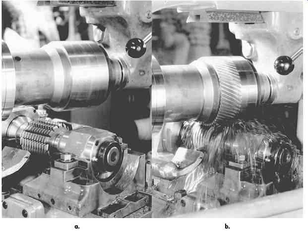
Fig. 56: (a) Setup for gang-hobbing four helical gears on
a hobbing machine. (b) Hob cutting the teeth on a
set of four helical gears. (Bourn & Koch Machine Tool Company)
Most hobs are manufactured from HSS. Car bide-tipped hobs are sometimes used for hobbing low-strength, abrasive, nonmetallic materials.