Workholding is one of the most important elements of the machining process. The term work holder includes all devices that hold, grip, or chuck a workpiece to safely perform a manufacturing operation. The holding force may be applied mechanically, electrically, hydraulically, or pneumatically. This section considers workholders used in traditional material-removing operations.
Basic Workholders
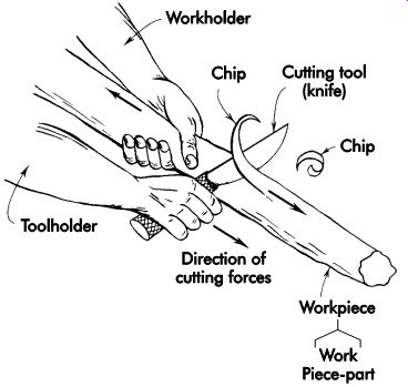
FIG. 1. Principles of workholders.
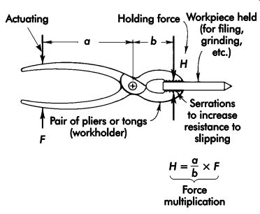
FIG. 2. Multiplication of holding force.
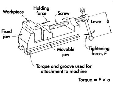
FIG. 3. Elementary workholder (vise).
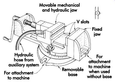
FIG. 4. Vise with hydraulic clamping.
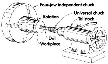
FIG. 5. Holding (chucking) a round workpiece.
FIG. 1 illustrates almost all of the basic elements present in a material-removing operation intended to shape a workpiece. The right hand is the toolholder, the left hand the workholder, the knife is the cutting tool, and the piece of wood is the workpiece. Both hands combine their motion to shape the piece of wood by removing material in the form of chips. The body of the person whose hands are shown may be considered a machine that imparts power, motion, position, and control to the elements shown. Except for the element of force multiplication, these basic elements may be found in all of the forms of manufacturing setups where toolholders and workholders are used.
FIG. 2 shows a pair of pliers or tongs used to hold a rod on which a point has to be ground or filed. This simple workholder illustrates the element of force multiplication by a lever action and serrations on the parts contacting the rod to increase resistance against slippage.
FIG. 3 shows a widely used workholder, the screw-operated vise. The screw pushes the movable jaw and multiplies the applied force. The vise remains locked by the self-locking characteristic of the screw, provides means of attachment to a machine, and permits precise placement of the work.
A vise with a number of refinements often used in workholders is depicted in FIG. 4.
The main holding force is supplied by hydraulic power, the screw being used only to bring the jaws in contact with a workpiece. The jaws may be replaceable inserts profiled to locate and fit a specific workpiece. Other, more complex jaw forms are used to match complicated workpieces.
Another large group of workholders represents chucks. They are attached to a variety of machine tools and used to hold a workpiece during turning, boring, drilling, grinding, and other rotary operations. Many types of chucks are available. Some are tightened manually with a wrench, others are power-operated by air or hydraulic methods or electric motors. On some chucks, each jaw is individually advanced and tightened, while others have all jaws advance in unison. FIG. 5 shows a workpiece clamped in a four-jaw independent chuck. The drill, which is removing material from the workpiece, is clamped in a universal chuck.
Workholder Purpose and Function
A workholder must position or locate a work piece in a definite relation to the cutting tool. It must withstand holding and cutting forces while maintaining a precise location. A workholder consists of several elements, each performing a certain function. Locating elements position the workpiece; the structure, or tool body, withstands the forces; brackets attach the workholder to the machine; and clamps, screws, and jaws apply holding forces. Elements may have manual or power activation. All functions must be performed with the required firmness of holding, accuracy of positioning, and a high degree of safety for the operator and equipment.
General considerations
The design or selection of a workholder is governed by many factors, the first being the physical characteristics of the workpiece. The workholder must be strong enough to support the workpiece without deflection. Workholder material must be carefully selected with the workpiece in mind so neither will be damaged by abrupt contact (for example, damage to a soft copper workpiece by hard steel jaws).
Cutting forces imposed by machining operations vary in magnitude and direction. A drilling, boring, or reaming operation induces thrust and torque, while a shaping or contour-forming operation causes straight-line thrust. The work holder must support the workpiece in opposition to the cutting forces. Workholders are generally designed for a specific machining operation.
The workholder establishes the location of the workpiece relative to the cutting tool. If the operation is to be performed at a precise location on the workpiece, locating between the workpiece and workholder must be equally precise. If a cut ting tool must engage the workpiece at a specified distance from a feature, such as a line or plane of the workpiece, then the workholder or workholding fixture must establish the line or plane at the specified distance. The degree of precision required in the workholder usually will exceed that of the workpiece because of cumulative error.
The strength and stiffness of the workpiece will determine to what extent it must be supported for the machining operation. If the workpiece design is such that it could be distorted or deflected by machining forces, the workholder must support the affected area. If the workpiece is sufficiently rigid to withstand machining forces, workholder support at the edge of the workpiece may be adequate. The strength of the workholder is determined by the direction and magnitude of the machining forces and weight of the workpiece.
Production requirements will greatly influence workholder design. If a large number of workpieces are to be processed, the cost of an elaborate workholder might well be offset by savings due to increased hourly production. High production rates and volume, therefore, can justify expensive fixturing. Conversely, if only one or two workpieces are to be machined, the operation usually will be performed with standard toolroom equipment since little to no fixturing costs can be justified. Production schedules may limit the time available for workholder acquisition and compel the use of standard equipment.
Safety requirements must always dictate workholder design or selection. A workholder must not only withstand normal cutting forces and workpiece weight, but it also may have to withstand large momentary loads. In machining a cast workpiece, the cutting tool might strike an oxide inclusion causing an instantaneous rise in force. The tool might cut through the inclusion, break, or stall. If the workholder breaks, however, the tool might impart motion to the workpiece.
A workpiece in uncontrolled motion is a missile.
The workholder also must be designed to protect workers from their own negligence. Where possible, a shield should be interposed between the worker and the tool.
A workholder should be designed to receive the workpiece in only one position. If a sym metric workpiece can be clamped in more than one position, it is probable that a percentage of workpieces will be incorrectly clamped and machined. Workholders should be designed to prevent incorrect placement and clamping.
It is advisable to use standard workholders and commercially available components whenever possible. Not only can these items be purchased for less than the cost of making them, but they are generally stronger and accurate.
Many workholders are used in other than material-removing operations. Workholders may be used for the inspection of workpieces, assembly, welding, and so on. There may be little difference in their basic design and appearance. Quite often, a standard commercial design may be used in one application and then again for the same or another workpiece in an inspection operation.
Locating and supporting Principles
To ensure the successful operation of a work holding device, the workpiece must be accurately located to establish a definite relationship between the cutting tool and some points or surfaces of the workpiece. This relationship is established by locators in the workholding device that position and restrict the workpiece to prevent movement from its predetermined location. The workholder then will present the workpiece to the cutting tool in the required relationship. The locating device should be designed so each successive workpiece, when loaded and clamped, will occupy the same position in the workholder. Various methods have been devised to effectively restrict the movement of workpieces. The locating design selected for a given workholder will depend on the nature of the workpiece, requirements of the metal-removing operation to be performed, and other restrictions on the workholder.
Answering the following questions will provide the basis for good locator design:
• Have locators been designed to allow easy loading and unloading?
• Could fragile parts bend or distort?
• Is the locator design the most appropriate for the workpiece?
• Are suspended portions of the workpiece properly supported?
• Can worn locators be replaced easily?
• Are economical locators used?
• Will ejectors, if used, interfere with locators?
• Have the most logical locators been used?
• Has a fool-proofing device been employed?
• Can location be simplified?
• Has the proper tolerance been applied to the locator?
• Are there any redundant locators?
• Are the locators positioned as far apart as possible?
• Will locators allow for in-tolerance variation of workpieces?
• Have diamond locators been used where appropriate?
• Are locators positioned away from the cutter path?
• Has locator contact been kept to a mini mum?
• Do vee locators locate the workpiece in the proper plane?
• Are locators positioned or relieved to avoid burrs or chips?
• Are locators properly positioned in relation to each other?
• Are machined surfaces used as locating surfaces when possible?
• Are adjustable locators used for cast surfaces? Workpiece surfaces
One major consideration involved in selecting locators for a workpiece is the shape of the locating surface. All workpiece surfaces can be divided into three basic categories insofar as lo cation is concerned: flat, cylindrical, and irregular. While most workpieces are a combination of different surfaces, the designer must identify which ones will be used to locate the part.
Flat surfaces are those which, regardless of their position, have a flat bearing area for the locators. Typical examples of flat surfaces include edges, flanges, steps, faces, shoulders, and slots.
Cylindrical surfaces are located on a circumference or diameter. Typical examples of cylindrical surfaces include internal (concave) surfaces of holes or external (convex) surfaces of turned cylinders.
Irregular surfaces provide neither a flat nor a cylindrical locating surface. Typical examples of irregular surfaces include many cast or forged workpieces. Since the category of irregular locating surfaces is so inclusive, it is necessary that every locating surface be grouped into one, and only one, of the three surface categories.
Location types
Basic workpiece location can be divided into three fundamental categories: plane, concentric, and radial. In many cases, more than one location category may be used for a particular workpiece. However, for the purpose of identification and explanation, each will be discussed individually.
Plane
Plane location normally is considered the act, or process, of locating a flat surface. Many times, however, irregular surfaces may be located this way as well. Plane location is simply locating a workpiece with Reference to a particular surface or plane (see FIG. 6).
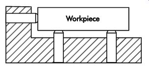
FIG. 6. Plane location.
Concentric
Concentric location is the process of locating a workpiece from an internal or external diameter (see FIG. 7).
Radial
Radial location normally is a supplement to concentric location. With radial location (FIG. 8), the workpiece is first located concentrically.
Then a specific point on the workpiece is located to provide a specific fixed relationship to the concentric locator.
Combined
Most workholders use a combination of locating methods to completely position a workpiece.
The part shown in FIG. 9 is an example of all three basic types of location being used to Reference a workpiece.
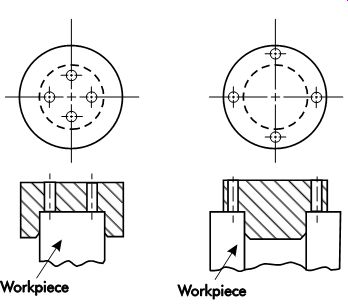
FIG. 7. Concentric location.
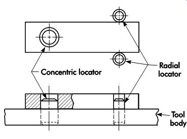
FIG. 8. Radial location.
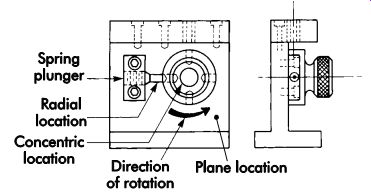
FIG. 9. Plane, concentric, and radial location.
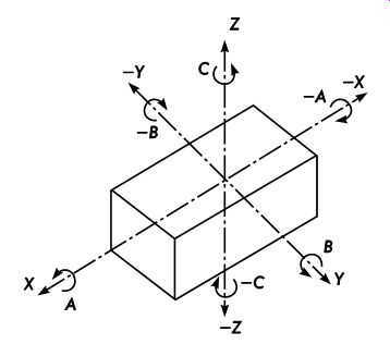
FIG. 10. Six degrees of freedom and 12 directions.
Degrees of Freedom
A workpiece in space, free to move in any direction, is designed around three mutually perpendicular planes and has six degrees of freedom.
It can move in either of two opposed directions (+ or -) along three mutually perpendicular axes, and can rotate in either of two opposed directions around each axis, clockwise (-) and counterclockwise (+). Each linear direction can be either positive or negative, and each rotation direction can be positive (counterclockwise) or negative (clockwise) as one looks at the origin (0, 0, 0). The six degrees of freedom as they apply to a rectangular prism are illustrated in FIG. 10.
Location Methods
To accurately locate a workpiece, it must be confined to restrict movement in all six degrees of freedom (12 directions) with exception of those called for by the operation. When this condition is satisfied, the workpiece is accurately and positively confined in the workholding device. It is important to indicate that the axis setup in FIG. 10 represents a device space orientation. Many computer-aided design (CAD) systems and horizontal machining centers transpose the Y and Z axes so that Y values are up (+) or down (?) and Z values are forward (+) and backward (?).
3-2-1 Method
A workpiece may be positively located by means of six pins positioned so that they collectively restrict the workpiece in nine directions.
This is known as the 3-2-1 method of location and is used primarily for controlling the degrees of freedom. FIG. 11 shows the prism resting on three pins, A, B, and C. The faces of the three pins supporting the prism form a plane parallel to the plane that contains the X and Y axes. The prism can neither rotate about the X and Y axes nor move downward in the Z direction. Therefore, directions (movements) one, two, three, four, and five have been restricted.
In FIG. 12, two additional pins, D and E, whose faces are in a plane parallel to the plane containing the X and Z axes, prevent rotation of the prism about the Z axis. It is not free to move to the left in direction nine. Therefore, directions six, seven, and nine are restricted, and the prism cannot rotate.
Finally, with the addition of pin F as shown in FIG. 13, direction eight is restricted. Thus, nine directional movements have been restricted by means of six locating points, three in a base plane, two in a vertical plane, and one in a plane perpendicular to the first two.
Three directions, 10, 11, and 12, still remain unrestricted. This is necessary for loading the workpiece into the workholder. The remaining three directions may be restricted with clamps, which also serve to resist the forces generated by the metal-removing operation being performed on the workpiece. Any combination of three clamping devices and locating pins may be used if this is more suitable to the design of a particular workholder.
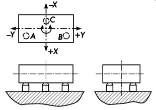
FIG. 11. Three pins arrest three directional movements.
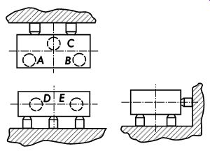
FIG. 12. Five pins arrest eight directional movements.
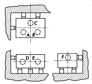
FIG. 13. Six pins arrest nine directional movements.
In summary, rectangular parts should generally use:
• three locators on the largest surface,
• two locators on the second largest surface, and
• one locator on the smallest surface.
Concentric and Radial Methods
A workpiece that is located concentrically and radially is restricted from moving in nine directions. FIG. 14 illustrates a typical workpiece located concentrically. The base and center pin restrict nine directional movements.
The base restricts any downward movement and rotation around the X and Y axes. The center locating pin prevents any movement in either a traverse or longitudinal direction along the X and Y axes. Located in this manner, the part is only free to move vertically or radially around the Z axis.
To prevent movement around the Z axis, a radial locator is positioned as illustrated in FIG. 15. In this position, both rotational directions (+ and ?) around the Z axis are restricted. The only possible movement this part can make is vertically, up the Z axis. This direction is restricted by the clamping device.
Basic rules
To function properly, locators must be positioned correctly, designed properly, and sized accurately. To do all this and still permit easy loading and unloading of the tool requires fore thought when planning the locational elements of a workholder. The following are a few basic principles every designer should keep in mind when planning part location.
Position and Number of Locators
Locators and part supports should always con tact a workpiece on a solid, stable point. When possible, the surface should be machined to en sure accurate location. Locating points should be chosen as far apart as possible on any single workpiece surface. Thus, for a given displacement of one locating point from another, the resulting deviation decreases as the distance between the points increases.
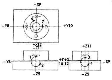
FIG. 14. Base and center pin restrict nine directional movements.
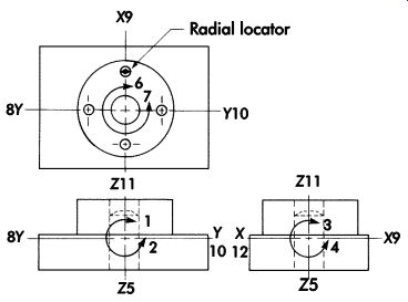
FIG. 15. Base, center pin, and radial locator restrict 11 directional movements.
Clamping will restrict Z11 if required.
The most satisfactory locating points are in mutually perpendicular planes. Other arrangements are possible but not desirable. Two disadvantages result when locating from other than perpendicular surfaces: (1) the consequent wedging action tends to lift the workpiece, (2) the displacement of a locating point or particle (chip or dirt) adhering to the workpiece introduces a correspondingly larger error. In FIG. 16 the introduced error, T, is projected to become the resulting error, E. The projection factor, F, is zero when the locating surfaces are perpendicular and increases as the angle between them becomes more acute.
Redundant Locators
Always avoid redundant or duplicate locators on any part. Redundant location occurs when more than one locator is used to locate a particular surface or plane of a workpiece. FIG. 17 shows examples of redundant location. The principal objection to using more than one locator, or series of locators, to Reference one location, is the variance in part sizes. Any variation in the part size, even within the tolerance, can cause the part to be improperly located or bind between the duplicate locators. Besides these obvious problems, it is not cost-effective to use more locators than necessary.
Locational Tolerances
Locational tolerance is one point that must always be considered when specifying locators for any workholder. As a general rule, locational tolerance should be approximately 20-50% of the part tolerance. Making the tolerance excessively tight only increases costs. Likewise, overly large tolerances can shorten the life of a workholder.
The designer must balance the cost against the expected life of the tool and required accuracy of parts to determine a locational tolerance that will provide the required number of parts without excessive tooling costs.
Foolproofing
Foolproofing is the process of positioning locators so a part will only fit in the workholder in its proper position. This is accomplished by a number of different means. The simplest and most cost-effective method is positioning a foolproofing pin to prevent incorrect loading (see FIG. 18). In any case where a part has the possibility of being loaded improperly, use a foolproofing device.
Locator types
Locators are made in a wide variety of shapes and sizes to accommodate the large range of workpiece configurations. In addition, commercial locators are available in many styles to suit their ever-increasing use. To properly design and specify an appropriate locator, the designer first must be familiar with the different types of locators commonly used in jig and fixture applications.
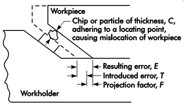
FIG. 16. Magnification and projection of error.
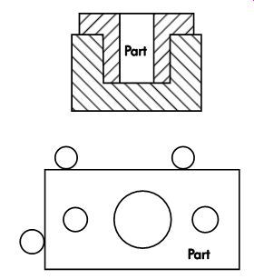
FIG. 17. Redundant locators.
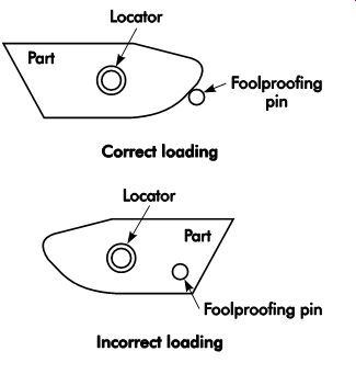
FIG. 18. Foolproofing.
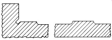
FIG. 19. Integral locators.
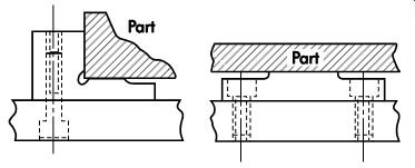
FIG. 20. Assembled locators.
External
External locators are used to position a part by its external surfaces. These locators normally are classified as either locators or supports. Locators are elements that prevent movement in a horizontal plane. Supports are locating devices positioned beneath the workpiece to prevent downward movement of the part and rotation around the horizontal axes. The two basic forms of external locators or supports are fixed or adjustable.
Fixed locators. These are solid locators that establish a fixed position for the workpiece. Typical examples of fixed locators include integral, assembled, pins, V-type, and locating nests.
Integral. Integral locators are machined into the body of the workholder (see FIG. 19). In most instances, this type of locating or supporting device is the least preferred. The principal objections to using integral locators are the added time required to machine the locator and the problem of replacing the locator if it wears or becomes damaged. Another drawback to using integral locators is the additional material required to allow for machining of the locator.
Commercial pin. Commercial pin locators are made in two general styles-plain and shouldered. Their ends are made in either round, flat, or bullet shapes to facilitate easy loading and unloading of parts. These locating pins are normally made between .0005-.0020 in. (0.013-0.051 mm) under size to prevent jamming and binding in the located hole. The installed end of these pins is generally .0625 in. (1.588 mm) smaller than the location end to prevent improper installation.
Commercial locating pins also are made in press-fit and slip-fit styles. Press-fit pins are installed directly into the tool body. Slip-fit pins are used along with liner bushings, which are installed into the tool body. A lock screw also is used to hold the pin in place.
Assembled. Assembled locators are similar to integral locators in that they both must be machined. However, these locators have the advantage of being replaceable. Assembled locators may be used as locators for supports (FIG. 20). Since they are not part of the major tool body, using assembled locators does not require additional material for the tool body. Assembled locators frequently are made of tool steel and hardened to prevent wear.
Pins. A locating pin is the simplest and most basic form of locating element. These locators may be made in-house from steel drill rod or purchased commercially. Commercial locating pins are available in several styles and types (see FIG. 21). Standard hardened dowel pins are another form of commercial component frequently used for locating devices. Due to their simplicity, easy application, and replaceability, round pins are the most commonly used.
The location and number of locating pins generally is determined by the size, shape, and configuration of the part. However, in most cases the 3-2-1 principle is applied, wherein there are three pins placed under the part to control five directional movements, and three more pins placed perpendicular to the base to control four more directional movements. The remaining two directional movements are con trolled by the clamping element.
Considerations other than location of the work piece will often affect the number of locating pins used. The workholding device must be designed to clamp the workpiece securely and support it to resist the forces generated by machining. If the operation performed applies considerable force, the workpiece may spring out of shape. Thus, the locating elements must be designed to provide adequate support for the workpiece against the forces acting upon it.
Many workpieces are essentially flat, or have a flat surface that can be used for locating purposes. These are commonly located by placing the workpiece on a plane surface to restrict it in five directional movements, as illustrated in FIG. 22. The addition of six locating pins, A, B, C, D, E, and F will restrict it in six more directions. The workpiece can move only in an upward direction.
This final movement is restrained by a suitable clamp having a plane surface parallel to the one on which the workpiece is placed. When this method of location is used, a great deal of planning must be done before specifying the locator positions. Since the workpiece is confined on all sides, the designer must specify locator positions that will not interfere with each other. Locators must be positioned to eliminate the possibility of duplicate location.
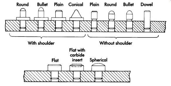
FIG. 21. Locating pins.
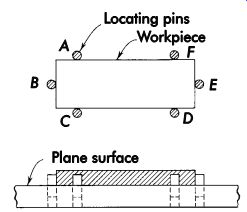
FIG. 22. Simple workholder made of plane surface and pins.
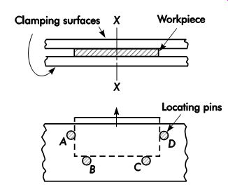
FIG. 23. Vertical locating with pins.
If the workpiece must be held in a vertical position, the same principle of clamping and supporting between two plane surfaces may be used. Again, this will restrict motion in six directions. Of the six remaining directions, only five must be restricted by locating pins (see FIG. 23). The four pins, A, B, C, and D, restrict motion downward, to the left and right, and both clockwise and counterclockwise around axis X. Gravity may be used to locate the workpiece and restrict movement during machining or other operations to be performed. Here again, locators must be positioned to minimize the chance of duplicate location.
V-type. A cylinder, like the prism, also has six degrees of freedom. The cylinder in FIG. 24 is free to move in two opposed directions along each axis and rotate both clockwise and counter clockwise around each axis. To accurately locate a cylindrical workpiece, it must be confined to restrict motion in each of its directions.
FIG. 25 shows a cylinder placed in the inter section of two perpendicular planes. The base plane is parallel to the X and Z axes, and the vertical plane is parallel to the Y and Z axes. The horizontal plane restricts movement in the two rotational freedoms around the X axis and the downward freedom along the Y axis. The vertical plane restricts the two rotational movements around the Y axis and the leftward movement along the X axis. The pin that forms the end stop restricts one directional movement (forward movement along the Z axis).
This corresponds to the basic 3-2-1 method of location used for the prism, but it restricts movement only in seven directions. The cylinder can move backward along the Z axis; in addition, it is free to rotate clockwise and counterclockwise around the Z axis.
Rotation around the Z axis can be restrained by clamping friction applied against the V formed by the two planes. This does not locate in a definite angular position about the Z axis and, therefore, cannot be considered true locating.
No provision has been made to accurately locate a particular point on the cylindrical surface.
In summary, cylindrical parts fall into two categories: short cylinder and long cylinder. A short cylinder generally requires that:
• three equivalent locators be used on the flat end,
• two equivalent locators be used on the circular edge, and
• friction be used to prevent rotation.
Long cylinders generally require that:
• four equivalent locators be used on the cylindrical surfaces,
• locator be placed on the flat end, and
• friction be used to prevent rotation.
Locating a cylinder in a V places its longitudinal axis in true location. Often, this is sufficient for the operation to be performed. In addition, the basic principle of V-location can be applied to workpieces that are not true cylinders but that contain cylindrical segments.
A single V-locator provides two points for locating where the cylindrical end of the workpiece is tangent to both sides of the V. The equivalent of three points in a base plane and a radial locator are required for complete location of the workpiece. In FIG. 26, a workpiece with two cylindrical ends is confined by means of two V-locators. The movable V-locator serves only to locate one point, the center of the cylindrical portion.
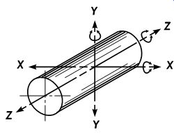
FIG. 24. Six degrees of freedom and 12 directions of a cylindrical workpiece.
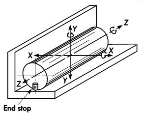
FIG. 25. Seven directional movements arrested by V-locator with stop pin.
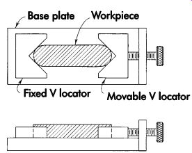
FIG. 26. Workholder with multiple V-locators.
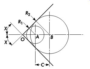
FIG. 27. Positions of circular sections of varying diameter in a V-locator.
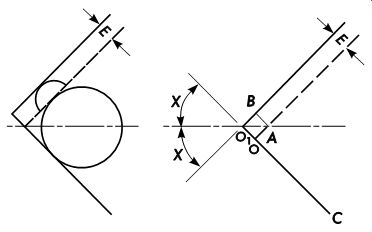
FIG. 28. Influence of the included angle or errors of location.
The included angle between the two surfaces of a V-locator governs the positions of circular sections of varying diameters (see FIG. 27). A V with an included angle of 2X locates a circle of radius R1 with center A and a circle of radius R2 with center B. The distance between centers = C.
By similar triangles:
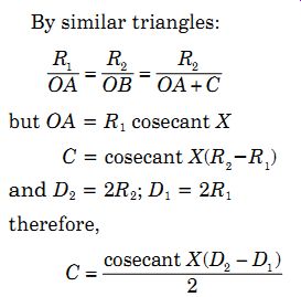
( 1)
( 2)
Consequently, the distance between positions of any two diameters in a V varies as one-half the included angle of the V. The smallest variation occurs when X = 90° and where cosecant However, as X approaches 90°, there is less inclination for the circular section to seat positively in the V and more difficulty in retaining it. Note that with X = 90°, 2X = 180° or a straight line.
The best compromise is achieved with X = 45°, and the included angle of the V is 90°.
Irregularities in the circular section of a work piece, or a chip lodged between the workpiece and the V locating surface, can introduce errors of location. The included angle of the V has a definite influence on the effect of such displacement. In FIG. 28, E is the displacement caused by a rough surface or chip. The circular section of the workpiece may be considered to rest on another side of the V indicated by a dot ted line. The displaced side of the V, shown by the solid line, forms a new V with the opposite side to define the displaced position of the circular section. The change in the position of the center of the workpiece is identical to the shift in the apex from the original to the new V. The original V is BOC and the new V is AO1C. The axis of the workpiece is displaced by the distance OO1. For a constant displacement E, OO1 is a minimum when 2X = 90°.
Consideration must be given to the axis of the rotating tool and its relationship with the position of the V-locator. The V locates the longitudinal axis of the cylindrical workpiece. When work is done perpendicular to this axis, the position of the V-locator should be arranged to keep displacement of the workpiece to a minimum. In FIG. 29a, a cylindrical workpiece is placed in a V-locator so a hole can be drilled perpendicular to the longitudinal axis. Any variation in the diameter of the workpiece will cause a displacement in the location of the vertical axis. The drill bushing, however, remains in its original position and the drilled hole will deviate from its required position by the amount of the displacement. In FIG. 29b, the V-locator is positioned so its axis is parallel to that of the drill bushing. Variation in the diameter of the work piece will cause no displacement of the vertical axis, and the drilled hole will not deviate from its required position.
Locating nests. The nesting method of location features a cavity in the workholding device into which the workpiece is placed and located. If the cavity is the same size and shape as the workpiece, this is an effective means of locating. FIG. 30 illustrates a nest that encloses the workpiece on its bottom surface and around the entire periphery. The only degree of freedom remaining is in an upward direction. A similar nest can be used to locate cylindrical workpieces. Cavity nests are used to locate a wide variety of workpieces regardless of the complexity of their shape. All that is necessary is to provide a cavity of the required size and shape.
Supplementary locating devices, such as pins, are not normally required.
The cavity nest has some disadvantages. Since the workpiece is completely surrounded, often it is difficult to lift out of the nest. This is particularly true when no portion of the workpiece projects out of the nest to afford a good grip for unloading. The workholding device can, of course, be turned over, and the workpiece shaken out. When the workpiece tends to stick, an ejecting device, such as an ejector pin or pins, can be incorporated in the workholder. This, however, adds time to the processing. Another disadvantage is that the operation performed may produce burrs on the workpiece that tend to lock it into the nest. In this case, the workpiece must be pried out or an ejector must be provided. Chips from the cutting operation may lodge in the nest and must be removed before loading the next work piece. Any remaining chips may interfere with proper positioning of the next workpiece.
To avoid the disadvantage of a cavity-type nest, partial nests often are used for locating. Flat members, shaped to fit portions of the workpiece, are fastened to the workholder to confine the workpiece between them. FIG. 31 shows two partial nests, each confining one end of a bow shaped workpiece. Each nest is fastened to the flat supporting surface of the workholder with two screws. Accurate positioning of the nests is ensured by dowels that prevent each nest from shifting from its required position.
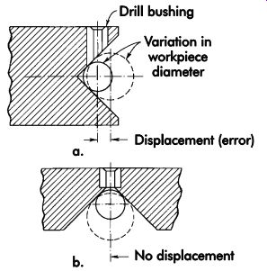
FIG. 29. Minimizing error by proper placement of a V-locator.
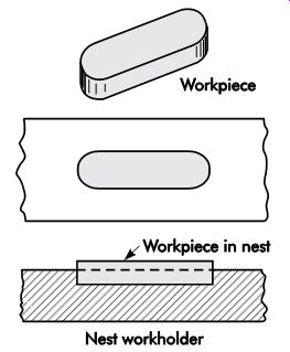
FIG. 30. Nest-type workholder.
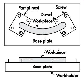
FIG. 31. Workholder with partial nests.
Partial nests eliminate many of the disadvantages of cavity nesting. Since they do not have the entire contour of the workpiece, they require less time to make. A partial nest does not completely confine the workpiece, so it is easily lifted out of the workholder. Normally, an ejecting device is not required. The cavity in each nest is open at one end to permit easy chip removal.
With the development of plastic casting materials, making cavities for locating workpieces has been simplified. The casting material can be poured around a workpiece prototype. After solidification and curing, the workpiece is removed.
The resulting cavity becomes the nest for locating workpieces during the production operation.
This method is much simpler than machining the cavity from a solid piece of material, and requires considerably less time, particularly when the workpiece is complex.
Many varieties of plastic materials are avail able, some with fillers of solid material, including steel or aluminum, to increase strength. Those with metallic fillers may be sawed, milled, drilled, and tapped after curing to a solid state. This machinability makes it easier to fasten the poured plastic cavity to the workholding device and eases alteration to accommodate future changes in the workpiece. Selection of the proper plastic depends on the forces generated by the operation to be performed, the quantity of parts to be made, and the effects of shrinkage of the material as it solidifies and cures.
Since plastic materials do not possess the strength of steels, plastic cavities often are reinforced with steel members. Reinforcements increase the resistance to tool forces, but do not materially increase the wear resistance of the plastic nesting surface. Consequently, plastic cavities generally are not used when large quantities of parts must be made. Also, if the plastic material used has a high degree of shrinkage, the resulting cavity may be too small to adequately locate the work. This, however, is not a critical factor since continuing improvements in the formulation of plastic compounds have consistently reduced inherent shrinkage.
Since the workpiece itself is required for the preparation of a nesting cavity, this type of work holder cannot be completed in advance of the production process. Of course, a prototype workpiece may be used, but making the prototype costs time and money so that the primary advantage of the cast locating cavity is lost. Therefore, the cavity is not usually made until production parts are available. This, however, does not usually cause a serious delay, since a cast cavity can be poured and cured in a few hours and be ready for use the following day.
A minimum-size workpiece must not be used for making the cavity since it will not accept parts that vary toward the maximum dimension.
When the contours of the workpiece permit, its surfaces can be built up to increase vital locating dimensions to ensure casting a cavity large enough to adequately locate a maximum-sized part. Often, this can be done by applying strips of thin masking tape to the proper surfaces of the workpiece.
Experience has developed the casting process of making locating cavities to the extent that a complete workholding device can be poured in one piece. FIG. 32 illustrates a plate-type drill jig made this way. The workpiece containing the required holes is laid on a flat surface. Round pins are pressed into the holes and project upward to locate the drill bushings, whose outer periphery is serrated to ensure a firm grip in the cast plastic.
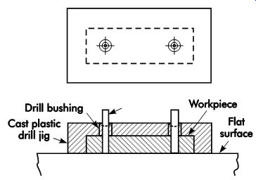
FIG. 32. Cast plastic, plate-type drill jig.
A dam may be made from four rectangular bars placed around the workpiece. The pins are then removed, and the drill jig is ready for use.
Other materials frequently used for casting locating nests are low-melt alloys. These bismuth, lead, tin, and antimony alloys are ideal for many difficult workholding and locating problems.
Quite often, low-melt alloys are used for applications where plastics cannot be used. One principal advantage to using low-melt alloys rather than plastic is their ability to be reused.
In use, the part is first positioned in a container. The container can be made of almost any material, such as sheet metal, low-carbon steel, or aluminum. Once positioned, the molten alloy is poured into the container and allowed to solidify.
The part is then removed, the nest cleaned, and all burrs removed. If the part has a configuration that prevents its removal from the cast alloy, it is machined in the encasing alloy and, when finished, the alloy is melted off the part. Frequently, additional materials, such as metal filings, ball bearings, or similar materials, are added to the alloy to add wear resistance and permit the nest to hold up under longer production runs.
Both plastic and low-melt alloys provide cost effective alternatives to expensive machined nests. The low initial costs and adaptability of these materials make them suitable for a wide range of workholding applications.
Adjustable locators. These are movable and frequently used for roughly cast or similar parts with surface irregularities. Examples of adjust able locators are threaded, spring pressure, and equalizing. Adjustable locators are used in con junction with fixed locators to permit variations in part sizes while maintaining the fixed relative position of the part against the fixed locators.
Adjustable locators are widely used for applications where the workpiece surface is irregular or where large variations between parts make solid locators impractical. The principal type of adjust able locator is the threaded style (see FIG. 33). In some cases, this type of locator also can be used as a clamping device rather than a locator (shown). However, this type is mostly used as a locator.
When adjustable locators are specified for a workholder, the position of the locator is not as critical as with solid locators, so the relative cost is greatly reduced. Frequently, adjustable locators are used as solid locators simply by adding a locknut, or screw, to secure the adjusting screw (FIG. 34).
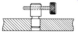
FIG. 33. Threaded adjustable locator.
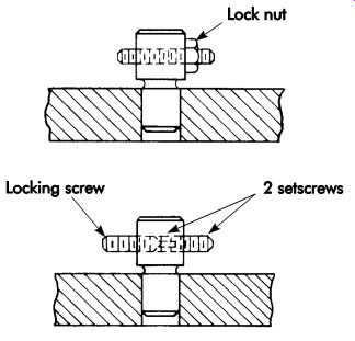
FIG. 34. Adjustable locators with locknut or screw.
Adjustable supports are simply adjustable locators positioned beneath the workpiece. Threaded supports are used along with solid supports to permit easy leveling of irregular parts in the workholder (FIG. 35). Spring supports also are used with solid supports to level the work piece. However, rather than using threads to elevate the locator, a secondary threaded element, such as a thumbscrew, is used to lock the position of the spring support (see FIG. 36). Equalizing supports are used to ensure constant contact of the supports and workpiece. These sup ports are normally self-adjusting. That is, as one is depressed, the other rises (FIG. 37).
Sight
Sight locators are an effective means of locating sand castings and similar rough and irregular parts for first-operation machining. These elements, while not locators in the conventional
sense, are well suited to applications where machined details must be in an approximate area rather than at a specific point. Sight location uses lines, slots, and holes in the workholder body to position the workpiece in an approximate position for machining. FIG. 38 shows two examples where sight locators are used to position a workpiece. In most cases, the part is simply centered between the sight locators and clamped before machining.
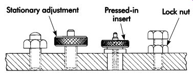
FIG. 35. Threaded-type adjustable supports.
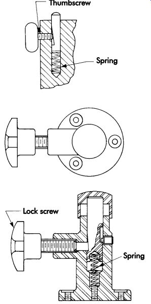
FIG. 36. Spring-type adjustable supports.
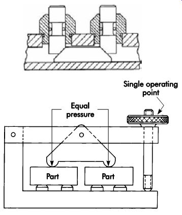
FIG. 37. Equalizing-type adjustable supports.
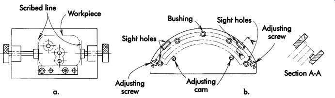
FIG. 38. Sight locators: (a) by scribed lines and (b) by sighting holes.
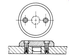
FIG. 39. Machined internal locator.
Internal
Internal locators are locating features, such as holes or bored diameters, used to locate a part by internal surfaces. The two basic forms of internal locators are fixed size and compensating. Fixed size locators are made to a specific size to suit a certain hole diameter and include machined, commercial pin, and relieved locators. Compensating locators generally are used to centralize the location of a part or allow larger variations in hole sizes. The two typical forms of compensating locators are conical and self-adjusting.
Machined internal. Machined internal locators are made to suit special-size hole diameters.
In most cases, machined locators are made for larger hole diameters. The exact form and shape of these locators normally are determined by the part to be located. They are generally machined to size and then attached to the tool using screws and dowels (FIG. 39). In cases where small-diameter locating pins are required, materials such as drill rod or commercial drill blanks are frequently purchased in the desired diameter and then cut to the required length.
Drill rod and drill blanks are normally available in most standard sizes.
When round plugs are used in holes for locating, there is a tendency to stick when a close-fit ting workpiece is applied. A plug of diameter, d, extending from a faceplate (FIG. 40a) will not stick in a hole within the diameter of a workpiece if the plug length:

( 3)
where:
L = plug length, in. (mm)
W = outside diameter of the workpiece concentric with the hole
C = (D - d)
D = hole diameter, in. (mm)
d = plug diameter, in. (mm)
A projection of diameter d on a workpiece will not stick in a locating hole (FIG. 40b) of diameter D if the hole is relieved or countersunk so that the length of engagement between the hole and workpiece is:

( 4)
where:
E = length of engagement, in. (mm)
m = depth of countersink, in. (mm)
A method of reducing the tendency for work pieces to stick on a locating plug extending from a faceplate is to relieve the plug by cutting away three equal segments (FIG. 40c). A workable value for the angle, ?, is 15°, which results in m = .35d. A plug cut away in this manner will not stick if its length,
L = 2.4 (2a + .085d)(D - d).
One disadvantage is that a workpiece can be displaced in three directions on a relieved plug, and the extra error in inches (millimeters) of location as compared with a full round plug is .207 (D - d), or about a 20% loss in locating accuracy.
An aligning groove may be put on the end of a plug of diameter, d, of unlimited length, L, to keep it from sticking when inserted in a hole of diameter, D (FIG. 40d). Workable dimensions for such a design are:
L = ?d (4-5)
L1
= 2AC2
= ?d B = .95d where:
A = plug alignment (pilot) diameter, in. (mm) C2
= clearance between the plug pilot and
hole
= (D - A) in. (mm)
? = coefficient of friction between plug and
hole surfaces, usually about .15 to .25
for steel
The pilot diameter may be made as convenient between size d and A = (2d2/D) ? d.
FIG. 39. Machined internal locator.
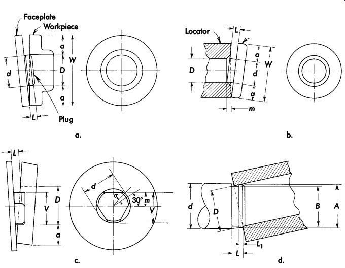
FIG. 40. Non-sticking locator design.
Relieved
Relieved locators, as their name implies, are designed to minimize the area of contact between the workpiece and locating pin. This reduces the chances of the locator sticking or jamming in the part. FIG. 41 shows several examples of relieved locators. The most commonly used form of relieved locator is the diamond pin.
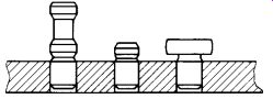
FIG. 41. Relieved locators.
Diamond pins. Diamond pins are used for radial location in conjunction with round locating pins. It is possible to accurately locate a work piece with two round pins, but allowances must be made for the variations encountered in hole sizes and locations. For instance, the distance between holes A and B (FIG. 42) will vary to the extent of tolerance X. Similarly, the distance between pins A and B in the workholder has a tolerance, Y. For accurate location, there should be an allowance between pin A and hole A of only a few ten-thousandths of an inch (micrometers). But, if pin B is a complete cylinder (same as pin A), the allowance between pin B and hole B must be at least as great as the sum of tolerances X and Y. This is necessary for the pins to engage holes within the permissible tolerance, X. The diameter of pin B can be calculated by:
B = HD - PT ( 6) where:
B = diameter of pin B, in. (mm) HD = minimum hole diameter, in. (mm) PT = sum of the center-to-center pin tolerance
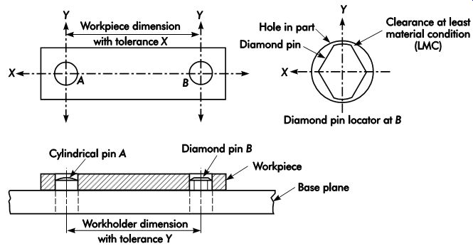
FIG. 42. Radial location with internal pins or plugs.
Extreme cases occur when both hole and pin center-to-center dimensions are at maximum or minimum conditions. As a result, there will be a large allowance between the hole and pin at B in the Y direction. This will permit an undesirable amount of radial rotation around the axis A and defeat the purpose for which pin B is intended.
To achieve more accurate radial location, B may be a diamond pin as shown in the inset in FIG. 42. It is relieved on two sides to allow for variations in the C direction, and has two cylindrical portions to locate the hole in the Y direction. The minimum radial movement of the workpiece occurs when the diameter of the cylindrical portion of the pin is smaller than the diameter of the hole by the allowance necessary to slip the minimum-size hole over the pin.
When positioning these locators in the tool body, the bearing surface of the diamond pin must be positioned to restrict movement of the part.
In some cases, the part may be completely located using diamond pins. In FIG. 43, the part is completely located by using two diamond pins placed to restrict the rotational movement of the part. When used in this fashion, the pins must be positioned to restrict the movement permitted by the other pin.
Floating locating pin. One other style of locating pin that will correct slight differences between locating holes is the floating locating pin (see FIG. 44). This pin provides precise location in one axis while allowing up to .125 in. (3.18 mm) movement in the perpendicular axis.
The body of the locator is pressed into the tool body. It is Referenced to the tool body and both the fixed and movable axes with a roll pin.
The floating locating pin generally works like a diamond pin. Due to the increased movement, however, this pin should be used for parts with somewhat looser locational tolerances on the mounting holes. The floating locating pin permits greater variation than that typically allowed by a diamond pin.
In FIG. 45, the floating locating pin is used along with a round locating pin. The part is first positioned on the round locator and then on the floating pin locator. This pin, when positioned as shown, prevents any radial movement about the round locator. It also compensates for differences of up to .125 in. (3.18 mm) in mounting-hole positions.
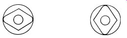
FIG. 43. Locating completely with diamond pins.
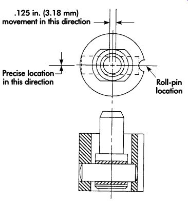
FIG. 44. Floating locating pin.
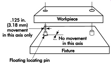
FIG. 45. Floating locating pin used in combination with round locating pins.
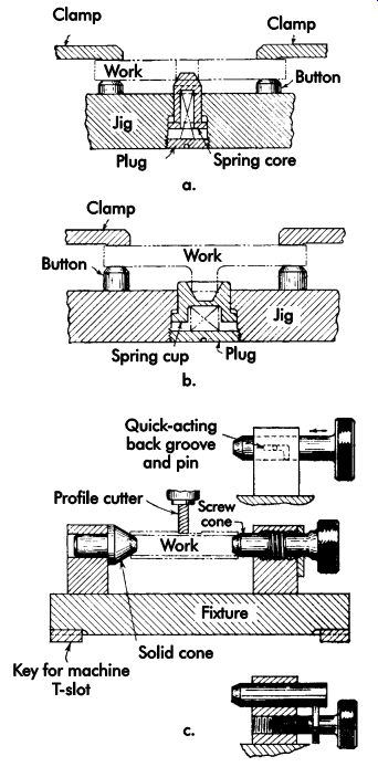
FIG. 46. Conical locators.
Conical
Conical locators are centralizing locators that compensate for variations in part sizes, as well as centering a part in the workholder. The most efficient types of conical locators are spring loaded or threaded (FIGs. 46a and 4-46b). Conical locators, while normally used for internal location, also may be used for external location with a conical cup (see FIG. 46c).
Self-adjusting Locators
Self-adjusting locators are used in applications such as sand casting, where there is great variation in the size of the holes to be located.
These locators can be made in a wide variety of styles. FIG. 47 illustrates one example of a self-adjusting locator that can be used for internal location.
Spring Locating Pins
Unless parts are properly positioned against locators, errors will result no matter how well a locating system is designed or made. One type of locating device that helps reduce these locational errors is the spring locating pin (FIG. 48).
Spring locating pins are designed to push the part against the fixed locators. This will ensure proper contact during the clamping operation.
Although spring locating pins are not actually locating devices, they help reduce locational errors by correctly positioning the part against the locators. In addition, these pins can eliminate the need for a third hand when positioning and clamping some parts. Their small size and compact design makes them useful for smaller parts or confined space. A protective rubber seal around the contact pin helps seal out debris and coolant.
Spring locator pins may be installed directly in a hole or mounted in an eccentric liner (FIG. 49). The liner permits pin adjustment to suit parts with looser tolerances (FIG. 50).
When positioning a flat plate (FIG. 51), the first step is to position the part over the workholder. The part then is placed against the solid locator and pushed down against the spring pin. When seated, the spring locating pins push the workpiece against the solid locator to ensure proper contact. These locating pins are well suited for a variety of applications and part shapes.
FIG. 47. Self-adjusting locator.
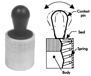
FIG. 48. Spring locating pin.
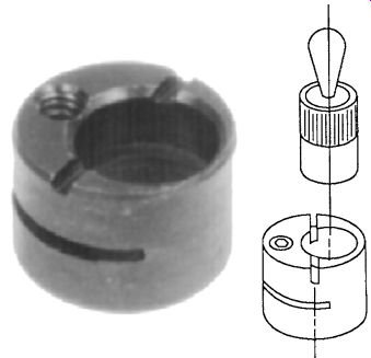
FIG. 49. Spring locating pin mounted in an eccentric liner.
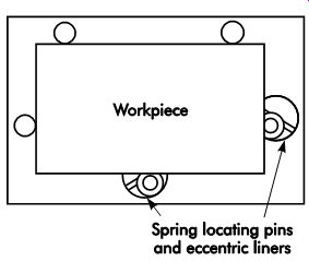
FIG. 50. Eccentric liner permits adjustment of the spring locating pins
for loose tolerance parts.
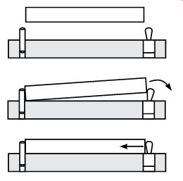
FIG. 51. Positioning a flat plate.
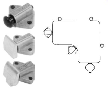
FIG. 52. Spring-stop buttons.
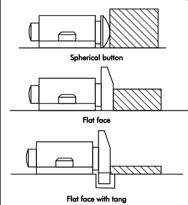
FIG. 53. Spring-stop buttons showing spherical and flat contacts.
Spring-stop buttons. FIG. 52 illustrates spring-stop buttons, another spring-loaded work holding device. They work much like the spring pins, but are designed for larger parts or where more force is needed. Spring-stop buttons are made with three different contact faces. The first is a spherical button contact. The other two have flat contacts. Flat face contacts are made with or without a tang (FIG. 53).
Chip and Burr Problems
Chips, burrs, and dirt on locating surfaces cause wear and disturb proper location. Every means must be provided to keep locating surfaces and points free from foreign matter. To keep chips and dirt under control:
• make locators easy to clean;
• make them self-cleaning, and
• protect them.
For easy cleaning, make locators as small as possible and consistent with adequate wearing qualities (rest buttons are popular). Jigs and fixtures should be as open as possible so sup ports are readily accessible and visible. Raise supports above surrounding surfaces so chips fall or can be readily swept off. Provide easy exit or passage avenues for chip ejection. Avoid pockets or obstructions where chips can collect and be difficult to clear.
Self-cleaning locators can have sharp edges or grooves that scrape dirt off of the workpiece surface as they slide across it. Relief around locating surfaces is essential as a means of escape for unwanted chips and dirt (FIG. 54). For corner relief, suitable recessor grooves are provided so dirt and chips do not pack into corners and burrs do not bear against locating surfaces.
Fixed wipers may push chips along as a fix ture is traversed on the table of a machine tool, or coolant may flush them away. Indiscriminate use of compressed air for blowing chips has its drawbacks because chips can be quite harmful when blown into ways and other bearing surfaces of machine tools. Shields and guards are used to control and gather blown chips.
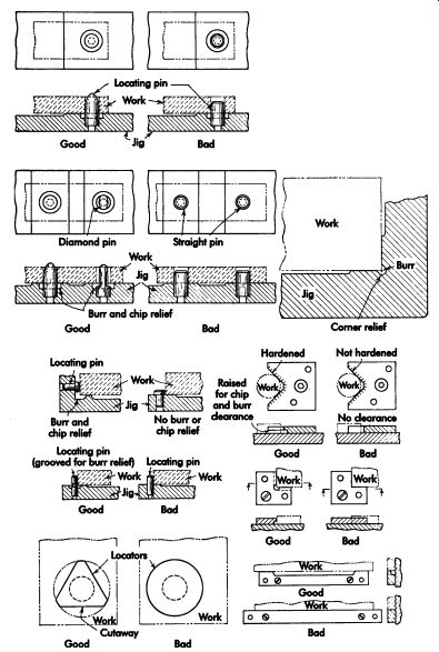
FIG. 54. Examples of proper chip clearance around locating pins and blocks.
The drill jig shown in FIG. 55 automatically cleans the jig and locating points prior to loading. An air valve is actuated by contact of the jig's top plate in the full-open position. The air blast is shut off as the top plate is lowered for each cycle. The chips are stopped by the shield.
An air blast in front of the cutter in FIG. 55b removes the chips in a milling operation. Continuous airflow of sufficient volume and pressure blows the chips into the catcher.
Suction is a means of removing light, discontinuous chips from the tool work area, particularly in dry grinding. Sometimes it is applicable when milling nonmetallic materials, such as phenolic and other compositions. A suitable mesh screen is provided at the mouth of the suction tube to keep clothes and other objects from entering.
Gravity slides can be used to control chips in a high-production setup for milling cast-iron parts.
Machine vibration induces the chips to slide into the trough between table and column where hinged pushers, fastened to the table, push the chips along. The chips accumulate in barrels at both ends of the trough.
A locating surface should be entirely covered by a workpiece when the fixture is loaded. If part of the locator is exposed, dirt and chips can collect on it during cutting, which may move over the locator as the workpiece is removed. Bearing surfaces, such as ways, and indexing mechanisms also should be protected from dirt and chips, which can cause excessive wear. Thus, slides, indexing pins, and buttons should be enclosed.
A burr that is raised on the work at the start of a cut is termed a minor burr; at the end of a cut, it is a major burr. Jigs should be designed so that removal of the workpiece is not hindered by burrs. In FIG. 56, work removal does not tend to shear the burrs since it parts the work and jig directly. In contrast, if the work must be slid across the burr, sticking complicates removal.
To avoid this, suitable clearance grooves or slots should be provided (FIG. 57).
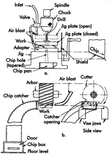
FIG. 55. Air blast used (a) to clean drill jig and (b)
in front of milling cutter to remove chips.
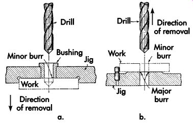
FIG. 56. Work removal does not tend to shear the burrs. The direction of
workpiece removal eliminates sticking of minor and major burrs.
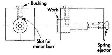
FIG. 57. Use of burr relief for the minor burr.
Clamping Principles
For a specific operation, the selection of general clamping-simple hand-operated clamps, quick-acting hand-operated clamps, power-operated clamps, etc.-should primarily be a function of operation analysis. The cost of the clamp must be balanced against the cost of the operation to obtain the lowest possible total cost for both fixture and operation.
The purpose of a clamp is to exert force and press a workpiece against the locating surfaces and hold it there in opposition to the actions of cutting or other processing forces. Clamping forces should be directed within the locating area, preferably through heavy sections of the workpiece directly upon locating spots or supports. Cutting forces should be taken by the fixed locators in a jig or fixture as much as possible, but generally some components of, or moments set up by, the cutting forces must be counteracted by clamping forces.
To be effective, a clamp should be designed to exert a minimum force equal to the largest force imposed upon it in the operation. It is essential that the tool designer exercise sound judgment when applying these clamping principles to the job at hand. In general, clamping arrangements should be as simple as possible.
The following design and operational factors should be considered:
• Simple clamps are preferred because complicated ones lose effectiveness as they wear.
Complicated arrangements tend to lose their effectiveness as the parts become worn, necessitating excessive maintenance, which might readily offset the savings of a faster operation.
• Some clamps are more suitable for large and heavy work, others for small pieces.
• Rough workpieces call for longer travel of the clamp in the clamping range, but clamps may be made to dig into rough surfaces to hold them firmly.
• The type of clamp required is determined by the kind of operation to which it is applied. A clamp suitable for holding a drill jig leaf may not be strong enough for a milling fixture.
• Clamps should not make loading and un loading the work difficult, nor should they interfere with the use of hoists and lifting devices for heavy work.
• Clamps that are apt to move on tightening, such as plain straps, should be avoided for production work.
• The anticipated frequency of setups may influence the clamping means. For example, the use of hydraulic clamps, even if simple and of low cost, might be inadvisable if frequent installation and removal of piping and valves are necessary.
Answering the following questions will provide the basis for making sound decisions as to good clamp design:
• Will the clamp securely hold the part in the tool?
• Has an equalizing device been used for multiple clamping tools?
• Does the clamp hold the part against the locators?
• Does the clamp operate quickly?
• Are a minimum number of clamps used?
• Will the clamp location interfere with cutters, loading, or unloading?
• Can clamp parts be easily replaced when worn?
• Are the clamps easy to operate?
• Does the clamp distort or bend the part?
• Can the clamp compensate for in-tolerance variations in part size?
• Is the clamping solid?
• Are clamps located over supports?
• Can the clamp be operated with one hand?
• Does the operator have to reach over or into the tool to activate the clamp?
• Is the tool thrust directed away from the clamps?
• Will the clamp contact damage the work piece surface?
• Are clamps self-contained or must wrenches be used?
• Is the clamp positioned away from the tool path?
• Can the clamps be operated within easy reach of the operator?
• Could vibration cause the clamp to loosen during use? tool Forces
A clear understanding of the direction and magnitude of cutting forces may eliminate the need to restrain all 12 directional movements of a workpiece. FIG. 58 shows how two pins and a table absorb the torque and thrust of a drilling operation. Although the workpiece is free to turn in a direction opposite to the torque, this freedom is insignificant unless a force is applied in that direction. No such force will be encountered in the planned drilling operation, and the remaining freedom need not be restrained. If, however, as part of the drilling operation, the spindle rotation is reversed for tool removal, such force will be encountered, and the freedom must be restrained.
Theoretically, there is no need to hold the work piece down, as this is accomplished by the thrust of the drill. When the drill breaks through the thickness of the workpiece, an upward force may be created by interaction between the drill flutes and material remaining around the periphery of the hole. If there is no restraint in this upward direction, the workpiece may be lifted above the pins, creating a dangerous condition. An upward force also may be produced when a drill or reamer gets lodged in a workpiece and the tool is to be withdrawn.
FIG. 59 shows how a workpiece must be restrained for tapping. Torque in both directions must be absorbed and the lifting pull of the tap resisted by some form of a hold-down, such as a clamp (not shown). For lead-screw tapping, torque resistance is still required, but no hold down is needed because the lead screw, having the same lead as the tap, eliminates all axial thrust.
When two holes are tapped simultaneously on a two-spindle setup, each tap prevents workpiece rotation by the torque exerted by the other tap.
However, this can result in lateral forces on the taps, which can cause their deflection. This can be a problem when the taps are of a small diameter. Without a lead screw, a hold-down would still be needed to prevent accidental lifting of the workpiece by the spindles.
FIG. 60 shows another instance where the cutting force holds the workpiece, in this case against the support plate of a horizontal broaching machine. The broach is guided in the support plate and, to some extent, the workpiece. The broach, in turn, also holds the workpiece. The cutting tool and cutting force both contribute to the workholding operation.
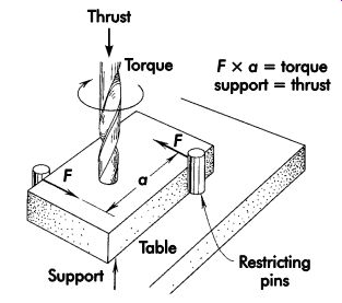
FIG. 58. Pin-type drill fixture resisting torque and thrust.
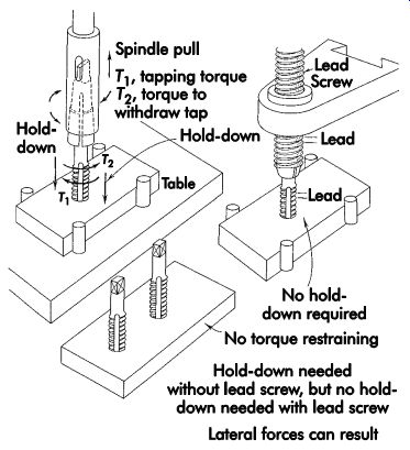
FIG. 59. Designing a workholder to resist torque and thrust in a tapping
operation.
Once the designer of a workholder has identified the possible direction and magnitude of forces, he or she has two ways to restrain the workpiece to counteract these forces. Strength and rigidity of some part of the workholder is used, against which the workpiece rests or is forced by a clamp, screw, or wedge. The other way uses friction between the workpiece surface contacting a surface of the workholder under pressure.
FIG. 61 illustrates a workpiece held in a vise. The horizontal component of the cutting force is absorbed by the solid jaw of the vise.
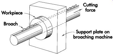
FIG. 60. Workholder for broaching operation.
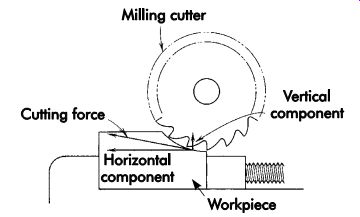
FIG. 61. Cutting force resisted by solid jaw of vise.
The vertical component is resisted by friction between the workpiece and the jaws. FIG. 62 shows the cutting force absorbed only by the friction between the jaws and the workpiece.
Wherever possible, cutting forces should be op posed by the structure of the workholder and, preferably, by the strongest and most rigid parts of it. If necessary, a movable element may be used to absorb cutting forces, but only if properly designed for strength and rigidity.
Complete analysis of tool forces in a proposed operation will disclose which of the 12 directional movements must be restrained and to what extent. Quite often, tool forces are of such magnitude and direction that a workpiece may be dislodged or moved from its required location. If the locating elements of a fixture cannot ensure adequate restraint, it may be necessary to clamp the workpiece against them.
Clamping Forces
Clamps hold a workpiece against a locator. Per haps the most common application is the bench vise, where a movable jaw exerts pressure on a workpiece, thereby holding it in a precise location determined by a fixed jaw. The bench vise uses a screw to convert actuating force into holding force. FIG. 63 shows a number of commonly used mechanical methods for transmitting a multiplying force.
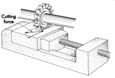
FIG. 62. Cutting force resisted only by friction.
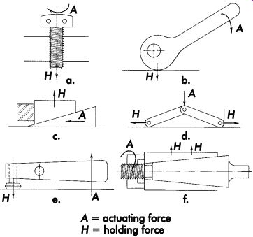
FIG. 63. Mechanical methods of transmitting and multiplying force: (a) screw,
(b) cam, (c) wedge, (d) toggle linkage, (e) lever, (f) combined screw and
wedge.
Clamping forces applied against a workpiece must counteract tool forces. Having accomplished this, further force is unnecessary and may be detrimental. The physical characteristics of the workpiece greatly influence clamping pressure.
Hard vise jaws can crush a soft, fragile workpiece.
The clamping pressure must hold, but not dam age, deform, or impose too great a load on the workpiece.
The direction and magnitude of clamping pressure must be consistent with the purpose of the operation. An example is the boring of a precise round hole with the workpiece clamped in a heavy vise. Excessive clamping pressure can compress the workpiece. The bored hole may be perfect in size and roundness while the workpiece is compressed. The release of clamping pressure might permit the workpiece to return to its normal condition, and the hole might then be off-size and elongated. Another example of excessive or misdirected clamping pressure may be found in a cutoff operation. If a workpiece clamped in a vise is to be cut between the jaws, in a direction parallel to the jaws, the removal of metal by the saw blade permits the remaining metal to flow into a cut area. This metal movement can effectively wedge and stop the saw blade.
Clamping pressure should not be directed to ward a cutting operation, but should, wherever possible, be parallel to it. Further, clamping pres sure should never be great enough to change any dimension of the workpiece.
Positioning clamps
Clamps must be positioned to contact a work piece at its most rigid point. When possible, they should be located over a locator or support to ensure that there is no tipping of the part during clamping. In cases where a part cannot be clamped over a locator, a secondary support must be installed to counteract the clamping forces and prevent damage to the part. As shown in FIG. 64, the flanged part is located by its center. If the part was clamped as shown in FIG. 64a, the part would distort. Therefore, a secondary support must be added (FIG. 64b). This additional support provides the required backing to prevent distorting the part.
Remember, when adding a secondary support, allow enough space between the support and the part to prevent redundant locating.
When clamping large rings or similar parts, the location of the clamping devices is very important to prevent warping or distorting the part. FIG. 65 shows two methods of clamping this type of workpiece. If the part were clamped as shown in FIG. 65a, the clamping forces could easily distort the part. However, if the clamps are positioned as shown in FIG. 65b, the chance of part distortion is greatly minimized.
Rigid versus Elastic Workholders
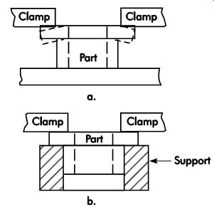
FIG. 64. Positioning clamps.
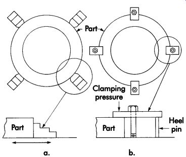
FIG. 65. Clamping large rings.
Workholders may be either rigid or elastic.
Since there are no absolutely rigid bodies and materials, "rigid" means the holding elements are preset to a fixed position. FIG. 66 shows a screw holding a workpiece as an example of rigid workholding. There is some elasticity in the screw and nut, but it is not intentionally provided.
As an example of elastic workholding, FIG. 67 illustrates a pressure-supported piston, which bears down on and holds the workpiece.
In FIG. 66, a sideways shift will bring the screw out of contact with a workpiece that is not of uniform thickness, causing complete loosening. The workpiece, however, resists any upward force against the screw because the screw is a self-locking, mechanically irreversible element.
In FIG. 67, the piston clamp will continue to exert holding force in case of a sideways shift.
An upward force is resisted only by hydraulic pressure exerted on the piston.
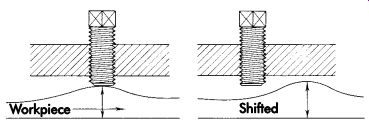
FIG. 66. Rigid workholding.
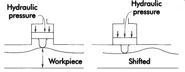
FIG. 67. Elastic workholding.
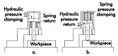
FIG. 68. Elastic workholding with self-contained, hydraulically operated
clamp cylinders.
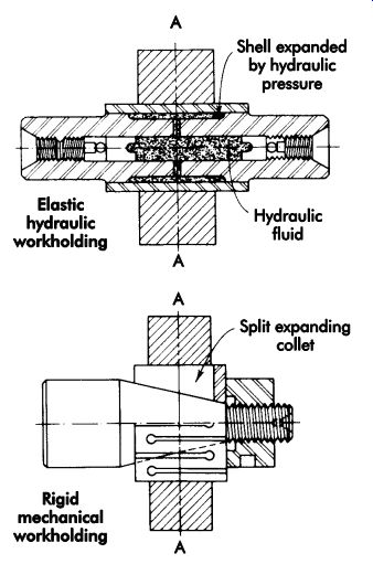
FIG. 69. Elastic and rigid mandrels.
FIG. 68 shows examples of elastic work holding using self-contained, hydraulically operated clamping cylinders. The workholder may be clamped by hydraulic pressure and released by spring pressure (a), or may be held by spring pressure and released by hydraulic pressure (b).
Air pressure may be used, but usually requires considerably larger piston areas to obtain sufficient holding force. The size of the cylinders may be reduced by the use of force-multiplying mechanical elements. Before elastic workholding devices can be used safely, forces on the work and their direction must be determined.
FIG. 69 compares a hydraulic mandrel for elastic workholding with a mechanical mandrel for rigid workholding. Hydraulic pressure is produced by a screw-piston arrangement.
Line A-A traces a path through a solid work piece, a solid expandable shell, and an elastic layer of a hydraulic compound. On a similar path, line A-A on the split-collet expanding mandrel passes through only consecutive layers of rigid metal. This does not mean that the elastic hydraulic mandrel is not as positive as the rigid mandrel. In fact, the opposite may be true. The hydraulic mandrel's torsional stiffness may be greater and it may possess many other desirable features, such as higher inherent precision and less vulnerability to dirt.
Clamp types
There are several basic types and styles of clamps and clamping devices commonly used for jigs and fixtures. The specific type of clamp selected for a particular application normally depends on the type of tool, part shape and size, and the operation to be performed. Other considerations, such as speed of operation and permanence, are factors that must be considered for long or high speed, high-volume production runs.
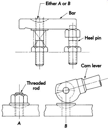
FIG. 70. Strap clamps.
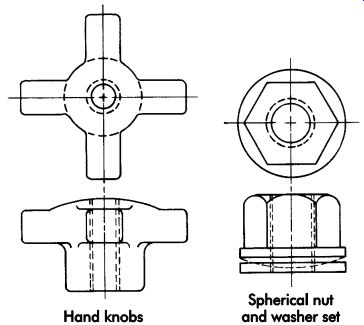
FIG. 71. Accessories for strap clamps.
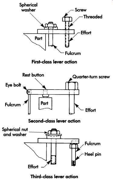
FIG. 72. Different classes of strap clamps.
Strap Clamps
Strap clamps are the simplest and least ex pensive type of clamping device used for jigs and fixtures. In FIG. 70, the basic strap clamp consists of a bar, a heel pin (or block), and either a threaded rod or cam lever to apply the holding force. Additional accessories for this type of clamp include hand knobs and spherical seat nut and washer sets (FIG. 71). Variations of the basic strap clamping system are illustrated in FIG. 72. The force, fulcrum, and work piece positions are altered to make differences in the lever classes of the strap clamps. Other variations of this basic type of clamp include the latch strap, sliding strap, and hinged strap clamp (FIG. 73).
Screw Clamps
Screw clamps are a type of mechanical clamp that uses a screw thread to apply the holding force. The two types of screw clamps generally used for jig and fixture work are classified as direct-pressure and indirect-pressure clamps. Direct-pressure clamps use the pressure of the screw thread to hold the workpiece. Typical examples are hook and swing clamps and quick-acting hand knobs (FIG. 74). Indirect-pressure clamps use the screw thread in combination with a secondary device to transmit the holding force of the thread.
The arrangement in FIG. 75 shows a typical application of an indirect-pressure screw clamp.
One additional benefit of using indirect-pressure screw clamps is that the holding force can be magnified by simply increasing the leverage of the holding member. This will permit the holding force to be two, three, or more times greater than the actuating force.
Cam-action Clamps
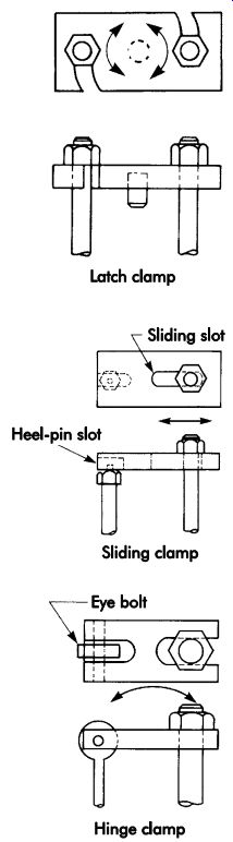
FIG. 73. Variations of the strap clamp.
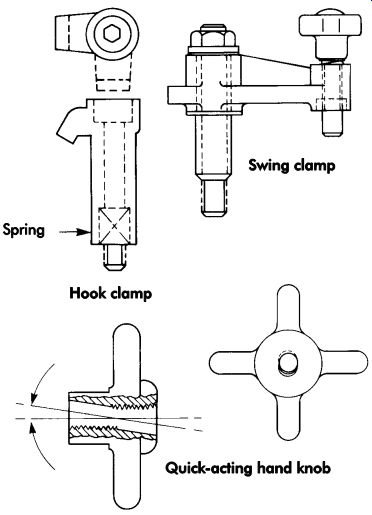
FIG. 74. Direct-pressure screw clamps.
Cam-action clamps frequently are used for fast operating clamping devices. The three principle types of cam-action clamps used for workholders are the flat eccentric, flat spiral, and cylindrical (FIG. 76). Flat eccentric cams operate on a high center principle and must be positioned exactly at the high center to hold properly. Flat spiral cams, on the other hand, have a locking range, which permits them to hold at any point within the range along the cam surface. Of these two styles, the flat spiral cam is the easiest and safest to use. All commercial cam-action clamps are made with this flat spiral cam design.
Both flat eccentric and flat spiral cams can be used for direct- or indirect-pressure applications (FIG. 77). Indirect pressure is the most efficient and safest design for jig and fixture work.
Direct-pressure cam clamps have a tendency to loosen during machining. Since indirect-pressure cams do not contact the workpiece, there is less chance for the vibration of the machining operation to loosen the cam.
Cylindrical cams also are used for workholding applications. With these clamps, the cam surface is generated on a cylindrical surface.
Toggle-action Clamps
Toggle-action clamps are commercially available and work with four general clamping motions: hold-down, push-pull, squeeze, and straight-pull. The main advantages of using toggle clamps are their fast clamping and releasing actions, their ability to move completely clear of the workpiece, and their high ratio of holding force to actuation force. Several variations of toggle clamps are available to suit almost every workholding application. FIG. 78 shows several different styles of toggle clamps commonly used for jig and fixture work.
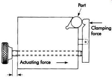
FIG. 75. Indirect-pressure clamp.
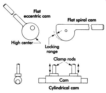
FIG. 76. Cam clamps.
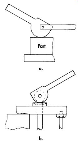
FIG. 77. Spiral cams used for direct (a) and indirect (b) pressure.
For all their advantages, standard toggle clamps have always caused problems because of their limited range of movement and inability to compensate for different thicknesses. Once set to a clamping height, the standard toggle clamp can only accommodate slight changes in workpiece thickness. Larger variations usually require adjustment of the clamp spindle. Now, however, with the automatic toggle clamp (FIG. 79), both these problems have been solved.
The standard toggle-clamp design uses a four bar linkage arrangement with fixed pivots and levers to produce the clamping action. Though adequate for many clamping operations, this de sign does not permit the automatic height adjustment needed for some parts. Rather than using only fixed points, the automatic toggle clamp has a self-adjusting feature to readjust the clamp to different workpiece heights. With this clamp, the handle, normally a fixed component, has a vari able length. The self-adjusting, self-locking wedge arrangement within the handle alters the pivot length to suit a variety of workpiece heights.
The clamp arm can accommodate differences in clamping heights of up to 15°. This results in a total automatic adjusting range of over 1.25 in. (31.8 mm). Added adjustment is permitted by manually moving the threaded spindle. Together, these adjustments result in a substantial amount of clamping capacity. To set up these clamps, the spindle extension first must be set to the average workpiece height (FIG. 80a). Once set, the clamp automatically adjusts to a considerable range of workpiece variations (see FIGs. 80b and 80c). Adjustments to the clamping force are made by turning a screw located in the end of the handle. This adjustment is made with a standard screwdriver. The holding capacity of this clamp is 750 lbf (3,336 N). The total movement of the vertical handle is 60° and the arm moves a total of 105° to permit easy workpiece loading and unloading.
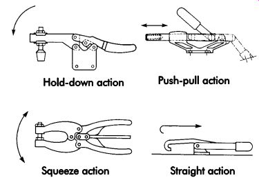
FIG. 78. Toggle clamps.
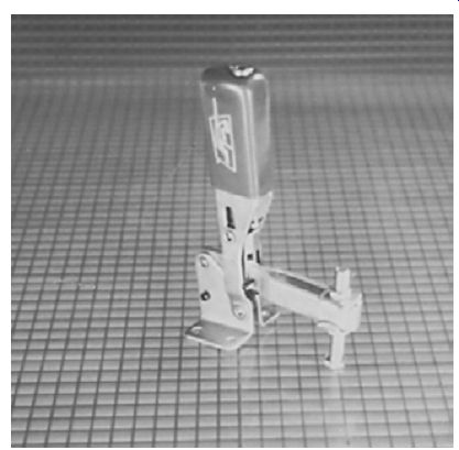
FIG. 79. Automatic toggle clamp.
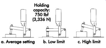
FIG. 80. Automatic adjustment to workpiece variations.
Wedge-action Clamps
Wedge-action clamps use the basic principle of the inclined plane to securely hold and clamp a workpiece. The two principal types of wedge clamps are flat and conical. The flat-wedge clamp (FIG. 81) works as a flat cam to provide holding force. The clamp is tightened and released by swinging the lever around the fulcrum pivot and contacting the inclined wedge against the spherical head pin. Conical wedges, or mandrels, normally are used in two styles, the solid mandrel and expansion mandrel (FIG. 82). The wedging action of the conical surface directly or indirectly holds the workpiece.
Specialty Clamps
In addition to the standard clamp variations, there is a group of clamping devices not as easily classified, which use a variety of nonstandard clamping actions. Incorporating the concept of a universal clamping system for today's multipurpose machine tools offers an almost endless range of possible applications. Unlike the limited purpose clamping devices usually found on machine tools, these can perform a majority of the necessary workholding operations while substantially reducing setup and part changeover time.
FIG. 81. Flat wedge clamp.
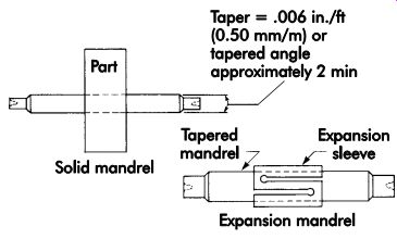
FIG. 82. Conical wedges.
FIG. 83. Mono-Bloc® clamp.
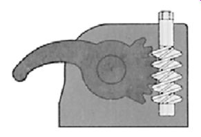
FIG. 84. Worm and worm-wheel clamp arrangement. (Royal Products)
The Mono-Bloc® clamp in FIG. 83 consists of a self-contained clamping unit that uses a worm and worm-wheel arrangement to perform the clamping action (FIG. 84). This allows the clamps to have a wide clamping range and complete adjustability.
These clamps are available in three different types or grades. The most common is the standard-duty model, as shown in FIG. 83. Light-duty and heavy-duty models are also available.
The standard-duty clamp is available with two different arm lengths, and has an extension arm that can be installed on the basic clamp. The clamping range may be increased by installing a series of 3-in. (76.2-mm) riser blocks under the base of the clamp. The riser blocks can extend the clamping range to a maximum height of 12 in. (304.8 mm). Both the basic clamp and riser blocks are assembled with a single screw. This allows the clamp assembly to be swiveled to any angle necessary to clamp the workpiece.
The Terrific 30® clamp (FIG. 85) is another form of universal clamp. It is retractable and operates from a single point. By simply turning the handle 1-1/2 turns, both the extension and clamping action are achieved (FIG. 86). Turning the handle in the opposite direction releases and retracts the clamp. This clamp may be mounted either directly to a machine table or on a series of riser elements. It also uses a single mounting screw, which allows the clamp to be positioned wherever necessary.
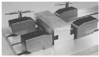
FIG. 85. Terrific 30® clamp. (Royal Products)
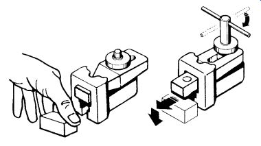
FIG. 86. Extension of clamp arm to hold workpiece.
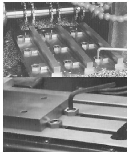
FIG. 87. MITEE-BITE® clamping system.
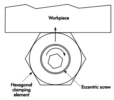
FIG. 88. Eccentric socket-head cap screw inside hexagonal clamping element.
Edge-clamping small or multiple parts may be difficult. Often, standard-edge gripping clamps are too large to suit the workpiece or setup. This usually forces a design compromise. Either the workholder must use larger standard clamps, thus reducing the number of parts clamped, or expensive special-purpose clamps must be custom made to hold the workpieces. An alternative is the MITEE-BITE® clamping system (FIG. 87). This clamping system has the design advantages of space-saving edge clamps with the cost savings of standard clamps. The clamp combines the security of a screw clamp and speed of a cam-action clamp into a single clamping de vice. It has an eccentric socket-head cap screw and hexagonal, brass clamping element (FIG. 88). The cam-action clamping movement is achieved by turning the screw inside the clamping element. This hexagonal element is made of brass so there is little chance of damaging the clamped workpiece. For special-purpose applications, stainless-steel clamping elements are also available. The cam action of this system results in a significant mechanical advantage that can apply up to 4,000 lbf (17,793 N) of holding force directly to the workpiece.
The clamps may be mounted directly to the tool body, or in a tee nut for use on a machine table. For applications where the workpiece must be elevated off the mounting surface, a riser clamp variation (FIG. 89) also is avail able. The riser clamp incorporates the benefits of the original basic clamp unit with the added flexibility of a small toe clamp. Rather than applying only lateral clamping force to hold the workpiece, the workpiece is held with both lateral and downward forces.
The basic clamps in the riser clamp set are mounted on a base element. This permits the clamps to be mounted directly in the tee slots of the machine table and provides the 10° clamping angle of the clamping element. The base element also establishes the mounting surface that holds the workpiece .50 in. (12.7 mm) off the machine table. The clamping element in the riser clamp is made of steel and has two clamping surfaces that can hold the workpiece. The first is a smooth surface that holds the workpiece without leaving clamp marks. The second is serrated to provide a better grip on the clamped surface. A clamp bar that works with the clamp to locate the opposite side of the workpiece during clamping is included with the basic clamp. It also has an end-stop unit mounted at the end of the bar (FIG. 90). This stop can be set to suit the desired location of the workpiece.
Chucks
Chucks are some of the most popular work holders used for jig and fixture work. These commercially made components allow a single workholder to service an infinite number of parts by simply changing or modifying the holding and locating surfaces of the tool.
Operations
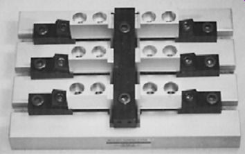
FIG. 89. Riser clamp variation of MITEE-BITE clamp.
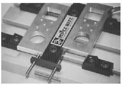
FIG. 90. Clamp bar with end-stop unit.
Chucking operations can be distinguished by the location at which they are performed on the workpiece. Common methods shown in FIG. 91 include (a) external chucking, (b) internal chucking, (c, d, k, l) endwise chucking, (e, f, g, h) holding or driving on centers, and (j) combi nations of these methods. Although differing workholders may be used, the differences are primarily in name and appearance rather than function or mechanical principles employed.
Motion is imparted to the workpiece by either friction or positive (preferred) means. In chucking, the jaw elements of the workholder bear on but do not positively engage the workpiece. The friction between the jaws and the workpiece rotates or drives the workpiece. Positive means for driving the workpiece can be provided by making use of its structure. Cutouts, keyways, gear teeth, or splines on a workpiece can be mated with matching elements on the workholder to give a positive drive. One distinguishing element can be found should failure occur: in a positive drive something breaks, while in a friction drive something slips.
Nomenclature
• A chuck is a workholder generally used for gripping the outside or end of a workpiece and it is usually attached to a machine-tool spindle.
• An arbor is a workholder generally used for internal chucking, holding, or gripping, and is usually attached to a machine-tool spindle.
• A mandrel is a workholder that, like an arbor, is used for internal chucking, holding, or gripping. Not generally as precise as an arbor, a mandrel is usually held between centers instead of being attached to the spindle.
• Range is the amount of variation in work piece diameter that can be accommodated by workholder expansion and contraction.
• Interference is the amount by which the chucking diameter in its holding condition (without the workpiece) differs from the diameter of the workpiece to be held.
• Chucking area is the area of the workholder that can be used for holding.
• Holding elements of workholders are called by various names depending on the type of workholder. They are the jaws on some chucks; fingers or prongs on some collets; expanding wedges or inserts on some arbors; expanding or contracting cylinders or sleeves on some special arbors and mandrels, and so on. These elements of the work holders are made to deflect by the actuating mechanism that transmits the force needed to operate the workholder. This force, in turn, may be applied manually or by power (pneumatic, hydraulic, or electric). Holding elements are backed up by the actuating elements; these are backed up by the operating mechanisms and forces.
Lathe Chucks
Lathe chucks consist of a body with inserted workholding jaws that slide radially in slots.
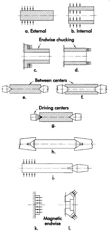
FIG. 91. Location and clamping of cylindrical or conical workpieces.
They are actuated by various mechanisms such as screws, scrolls, levers, and cams, alone and in a variety of combinations (see FIG. 92). The number of jaws varies. Chucks in which all of the jaws move together are self-centering and used primarily for round work. Two-jaw chucks operate somewhat like a vise, and may hold round and irregularly shaped workpieces by the use of suitably shaped jaws or jaw inserts. In dependent jaw chucks permit each jaw to move independently for chucking irregularly shaped workpieces or centering a round workpiece. The accuracy of a chuck deteriorates with use from wear, dirt, and deformation caused by excessive tightening.
The jaws of most lathe chucks can be reversed to switch from external to internal chucking.
Jaws may be adapted to fit workpiece shapes that are not round. The means of attaching a lathe chuck to different machine tools have been well standardized, so chucks made by different manufacturers can be easily interchanged.
In addition to their standard jaws, lathe chucks also may be fitted with a variety of special-purpose jaws to accommodate different types of workpiece surfaces and configurations.
The principal types of chuck jaws used for these purposes are called soft jaws and generally are made of cast aluminum. The two standard forms of soft jaws are regular soft jaws and pie-type soft jaws (FIG. 93). Regular soft jaws resemble standard jaws since they are made to the same width as the jaw carrier in the chuck. Pie-type soft jaws are much larger and completely cover the face of the chuck. In use, these jaws are first attached to the chuck, and the chuck is tightened. The desired form or shape then is machined into the soft jaws, forming a type of partial or full nest. Once machined to a size slightly smaller than the part size, the normal operation of the chuck securely holds and locates the parts to be machined.
Another type of soft jaw sometimes employed for large chucks uses an insertable element in either the top or end of the jaw (FIG. 94). This arrangement reduces the cost of replacing the entire set of jaws and the space required to stock and store machine jaw inserts. Since only the small insert is machined, the major body of the jaw can be used repeatedly for any number of different inserts. FIG. 95 shows a few examples of how these inserts may be machined to suit a variety of workpieces.
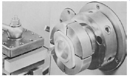
FIG. 92. Lathe chucks.
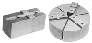
FIG. 93. Soft jaws.
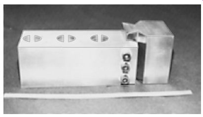
FIG. 94. Insertable element for soft jaws.
Solid Arbors and Mandrels
The solid, slender-taper mandrel (FIG. 96) is about the simplest possible workholder for round workpieces. Its main characteristic is a slightly tapered chucking surface with a taper of .004-.006 in./ft (0.33-0.50 mm/m). The workpiece diameter must be smaller than the largest diameter of the mandrel. The workpiece is forcibly pushed end wise onto the mandrel. This produces a gripping force around the hole in the workpiece, decreasing axially in relation to the interference produced between the outer diameter of the mandrel and inner diameter of the workpiece. The driving torque that can be transmitted depends on the radial gripping and tangential friction forces produced. The resistance against axial slipping depends on the axial friction forces produced.
It is not always easy to obtain the same driving power or position the workpiece to a definite stop when trying to control the resulting interference between the workpiece and mandrel. Pressing the workpiece on the mandrel requires an arbor press.
This procedure is slow and may damage the finish of the workpiece bore and score the mandrel. Work pieces with accurate round and straight bores are held with great accuracy on the simple mandrel in FIG. 96. If the bore is not round and straight, the workpiece and mandrel will mutually distort under the forces used to press on the workpiece.
Straight Mandrel
A straight mandrel resembles the mandrel in FIG. 96, but has a straight (untapered) chucking area. To produce the required press fit, the outer diameter of this mandrel is made larger than the bore of the workpiece by an amount called the interference. The amount of permissible interference is determined by the wall thickness, diameter, and material of the workpiece. It must be controlled to avoid exceeding the elastic limits of the workpiece and mandrel. Exceeding such limits could produce a change in bore diameter, especially in materials of low strength and with a low modulus of elasticity.
The obtained driving torque together with the axial resistance to slipping depends on the interference and is not easy to control. Possible mandrel wear and damage to the workpiece offset the advantages of the simple low-cost design. The range of interference-fit mandrels is limited.
Combination Slender Taper and Straight Mandrel
The combination slender taper and straight mandrel has a short, tapered chucking length followed by a straight length. The straight area fits snugly into the workpiece without interference and helps pre-align the bore. The tapered surface provides the driving area. To obtain reliable results for torque, accuracy, and axial location, hole tolerances must be carefully held.
Like the taper and straight mandrels, this type also requires a press-fit condition between the workpiece and chucking surface. The larger diameter of the mandrel is forced into the smaller bore of the workpiece. This axial pressing often damages the workpiece and workholder.
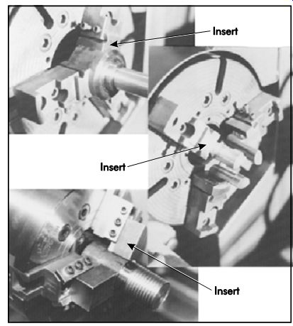
FIG. 95. Inserts may be machined.
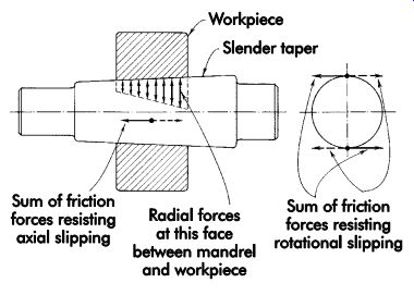
FIG. 96. Solid mandrel.
Solid Expanding Mandrels
The hydraulic mandrel and roll-lock type of arbor (FIG. 97) produce a shrink-fit by expanding tubular shells that are not split lengthwise.
The internal actuating mechanism expands the shell into the workpiece bore, and the amount of press-fit produced can be controlled by stops limiting the amount of expansion. The hydraulic type expands by hydraulic pressure; the roll-lock type expands by the gradual rolling and wedging action of straight rollers between the tapered inner diameter of the shell and a tapered plug, which is turned by a wrench.
Mandrels with a chucking area not weakened by axial slots generally have only small ranges.
The solid mandrel will permit a resulting interference of .0010-.0020 in./in. (0.001-0.002 mm/mm) of diameter. Hydraulic and roll-lock workholders expand from .0020-.0030 in./in. (0.002-0.003 mm/mm) of diameter. The obtain able accuracy is approximately 10-20% of the range of the workholder. A mandrel expanding .002 in. (0.05 mm) may then hold a round piece within a .0002-.0004 in. (0.005-0.010 mm) total indicator reading, or .0001-.0002 in. (0.003-0.005 mm) eccentricity.
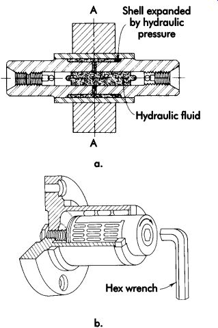
FIG. 97. (a) Elastic hydraulic workholding. (b) Roll lock expanding solid
mandrel.
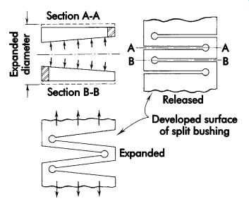
FIG. 98. Expansion of a split bushing.
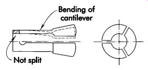
FIG. 99. Split collet.
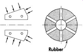
FIG. 100. High-range type collet.
Split-collet and Bushing Workholders
Solid expanding mandrels have a very small range. To increase range and hold workpieces with larger diameter variations, split collets and bushings are used. These are basically slotted shells of various shapes. The slots permit greater flexibility to increase for internal chucking and decrease for external chucking. The more flexibility provided, the greater the range. The shell splits and acts as a spring (FIG. 98). FIG. 99 shows a popular collet in which the range is obtained by cantilever deflection. The cantilevers are produced by splitting the collet from one end only and leaving a solid ring on the other. FIG. 100 shows a high-range collet where great flexibility is obtained by imbedding loose individual collet jaws in a suitable rubber compound.
Many varieties of chucking elements (FIGs. 98, 99, and 100) form the basis of various workholders. They are used for internal and external chucking, and are actuated in most cases by cones or tapers acting on corresponding surfaces of the chucking elements. Some work holders use small, self-locking tapers since a force must be applied to disengage the mating tapers.
A taper of less than 10° is usually self-locking (FIG. 101). Above 12-16°, the taper becomes self-releasing and requires force only to engage the mating tapers (FIG. 102).
Split collets and bushings, made with care, give satisfactory results for most applications. How ever, they are hard to maintain where extreme accuracies are required, and are vulnerable to the entry of dirt and wear on the sliding surfaces.
Standard 5C collets, step collets, and step chucks may serve as workholders for a wide variety of parts. Standard 5C collets are avail able in a wide range of sizes and shapes (FIG. 103). In addition, un-machined, soft emergency collets, step collets, and step chucks also may be machined to suit any particular part shape or configuration (FIG. 104).
Axial location
Moving collets provide axial location for work pieces. FIG. 105a shows a collet chuck, the diameter of which contracts upon axial motion.
FIG. 105b shows a collet mandrel that expands upon axial motion. At first, the clearance between the workpiece diameter and chucking diameter is closed; upon sufficient axial motion, a shrink-fit is created between the workholder and workpiece. As soon as contact is made at the chucking surface, the workpiece has a tendency to move together with the collet relative to the workpiece holder body. This movement produces an axial shift of the workpiece and prevents precise axial location.
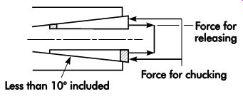
FIG. 101. Collet with self-locking taper.
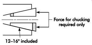
FIG. 102. Collet with self-releasing taper.
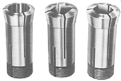
FIG. 103. Collets are available in a wide range of sizes and standard shapes.
FIG. 106 shows a method of obtaining precise location by providing a stop surface. The collet moves the workpiece toward and pushes it firmly against the stop. Some slipping occurs between the collet and workpiece during the chucking operation. This slippage tends to reduce the driving power of the workholder by absorbing part of the actuating force, and the mechanical efficiency of the chucking operation is thus lowered. To obtain accuracy, the stop surfaces of the workholder and faces of the workpiece must be square with the centerline. Lack of squareness may cause distortion of the arbor from one-sided loading against the stop surface (FIG. 107).
FIG. 108 shows a collet arrangement de signed to eliminate axial shift by not moving the collet. An intermediate bushing interacts with the tapered surfaces of the collet. An additional element with more mating surfaces between the two cylinders is thus introduced. The need to produce additional surfaces to a high dimensional and relational accuracy will lower the resultant final accuracy of the workholder. The more mating surfaces required in any workholder, the lower the accuracy.
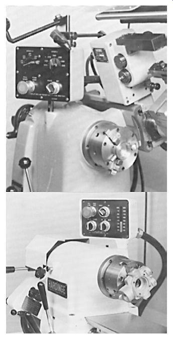
FIG. 104. Some collets and chucks may be machined to suit part shapes and
configurations.
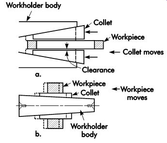
FIG. 105. Axial location of workpieces as affected by collets.
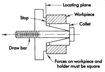
FIG. 106. Collet with stop plate to ensure correct axial location.
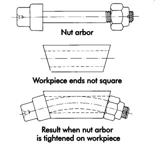
FIG. 107. Distortion caused by lack of squareness.
Some frequently used workholders have sliding elements or inserts actuated by movement on inclined planes (FIG. 109). They are similar to a lathe chuck in that their jaws or driving keys are held, guided, or moved in the workholder body.
The actuating mechanism consists of a bar with inclined wedge surfaces. The body, jaws, and bar are three different elements working together.
Accuracy depends on excellence of workmanship and careful use. A desirable simplification is the combination of the actuating mechanism with the workholder body. These workholders usually are built as arbors and mandrels, and have good range and gripping power. They are useful tools for even the largest tubular workpieces.
Self-actuating Wedge cam and Wedge-roller Workholders
Self-actuating wedge cam and wedge-roller workholders are tightened by the tangential work force of the cutting tools. They actuate them selves once the holding elements are brought even slightly into contact with the workpiece.
FIG. 110 illustrates an arbor using the principle of the roller clutch. One or more rollers are nested in cutouts in the body of the workholder and retained by wire clips. Turning the workpiece in the direction shown (relative to the workholder) wedges the rolls between the workpiece and workholder. An increase in the applied cutting force increases the wedging action almost proportionally.
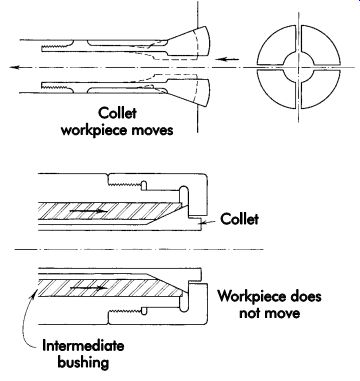
FIG. 108. Collet with intermediate bushing to eliminate axial shift.
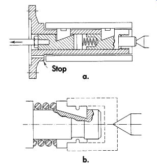
FIG. 109. Collets for internal chucking.
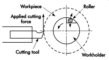
FIG. 110. Roller-clutch-type arbor.
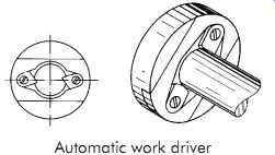
FIG. 111. Wedge-cam-type chuck.
The wedge-cam chuck (FIG. 111) has two inwardly spring-loaded cams. The jaws are lifted by a ring (not shown), then released until they touch the workpiece. Cam surfaces usually are serrated to obtain a better grip. Tangential cut ting forces wedge the cam jaws tightly against the workpiece.
Vises
Vises are perhaps the most widely used and best known workholders. All vises have in common one fixed and one movable jaw that hold a workpiece between them. All other features, such as configuration of the jaws to grip particular workpieces, means of actuation and mounting, ability to position the workpiece, and sizes, contribute to an endless variety of vises commercially available.
A vise is a good basic workholder element. By reworking the jaws or making special jaws, and adding details such as locating pins, bushings, and plates, vises can be easily converted into efficient, specialized workholders.
A common, heavy, plain vise is used for holding flat workpieces (FIG. 3). With V-shaped grooves in the jaws, it can locate round work pieces such as bars and tubing. A vise mounted on a rotary base permits angular rotation, positioning, and locking as may be required (FIG. 4). FIG. 112 shows a universal vise that can position a workpiece at any angle relative to the cutting tool.
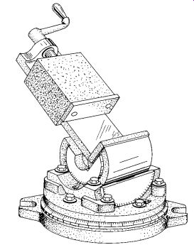
FIG. 112. Universal-type vise.
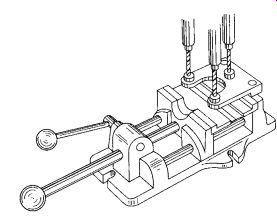
FIG. 113. Drill jig with quick-acting vise.
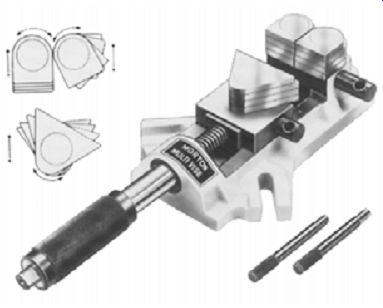
FIG. 114. Vise with three movable gripping areas.
FIG. 113 shows a workholder using a vise with a quick-acting jaw, which is moved rapidly into contact with the workpiece. A handle-operated cam then locks the movable jaw to produce great holding force. A special plate attached to the vise precisely positions three guide bushings in relation to the fixed (locator) jaw of the vise.
Another variation of this type of vise has a solid jaw made with a drill bushing mounted in movable arms. An end stop also is incorporated into the solid jaw. This type of vise is adaptable for many different types and shapes of workpieces.
FIG. 114 illustrates a vise particularly well suited for jig and fixture work. As shown, the three gripping areas of this vise are completely movable and can be locked to accommodate almost any part shape within the range of the vise.
Another form of special-purpose vise is the vertical vise (FIG. 115). It is useful for applications where a standard milling-machine vise cannot provide adequate support. The height of the workpiece can be regulated by the position of the stop bar (FIG. 116). These bars are movable in .50 in. (12.7 mm) increments for the complete width of the vise jaw and made in sets to match the range of openings for the vise.
Another style of vise ideally suited for a variety of different-size workpieces is the Bi-Lok® machine vise (FIG. 117). This vise is designed to hold either identical parts or two completely different sized parts (FIG. 118). The vise mechanism is totally self-compensating, and the same pressure is applied on both gripping positions regardless of the part sizes.
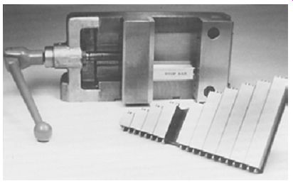
FIG. 115. Vertical vise.
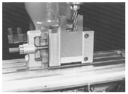
FIG. 116. Regulating workpiece height using a stop bar. (Mid-State Machine
Products, Inc.)
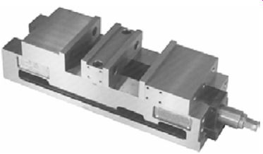
FIG. 117. Bi-Lok® machine vise.
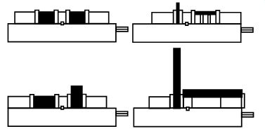
FIG. 118. Vise mechanism self-compensates to apply equal pressure regardless
of part size. (Chick Machine Co.)
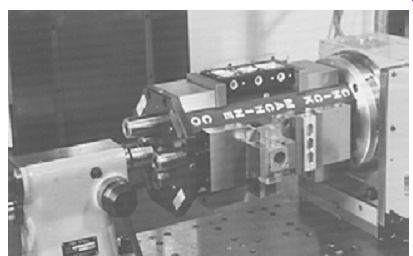
FIG. 119. Multi-Lok® vise.
The same operating principle used for the Bi-Lok vise also is applied to the Multi-Lok® vise (FIG. 119). A group of vises is mounted together in units of two, four, eight, or more to hold a series of identical parts, or a variety of different parts. This unit may be used for either horizontal or vertical machining operations. The individual jaws on the Multi-Lok are removable and may be replaced with soft jaws machined to suit specific part shapes.
Despite their many applications, most milling-machine vises cannot hold odd shapes or multiple workpieces. These parts often require expensive dedicated fixturing. The workholding system (FIG. 120) corrects the problems of conventional vise designs and reduces the need for dedicated fixtures. The unit consists of two moving blocks that replace the movable jaw on any standard angle-locking-type vise. These moving blocks can hold either single or multiple parts and have the unique ability of applying holding forces in both horizontal and vertical directions.
FIG. 121 shows several of the setup possibilities of this jaw unit. Setup 1 illustrates how this system holds a rectangular part. Two parts also can be held as shown in setup 2. A removable stop may be positioned on the solid jaw to act as a Reference point for mounting both parts. If the part has two different clamping surfaces as in setup 3, the jaws will accommodate the variations. The jaws also may be used to hold round parts (see setup 4). Each of the jaw elements is keyed to the moving block, and the side of one jaw element may be used to establish a perpendicular mounting plane for smaller parts (setup 5).
When the clamping elements are mounted to the pistons, a completely new set of clamping options are available. Mounting a set of swivel jaws to the piston allows the unit to hold both tapered and larger round parts (setups 6 and 7). Odd shapes and contours may be held by simply using a set of soft swivel jaws made to conform to the part shape (setup 8). The setup shown in 9 is useful for machining three sides of a part in one setup. A set of strap clamps are mounted in the pistons to hold the part. Even setups involving multiple small parts (setup 10) are easily performed using another set of swivel jaws. Clamping action is obtained by inserting an anvil plate against the sides of the parts. As the vise is tightened, swivel jaws contact the anvil plate and push it against the parts. As the pressure increases, the jaws pivot and apply the necessary holding force to both ends of the stacked parts.
Special Jaws
The usefulness of vise-like workholders can be enhanced by making special cast and molded jaws, which adapt to the holding and locating of complex workpieces. There are two methods for making these special jaws.
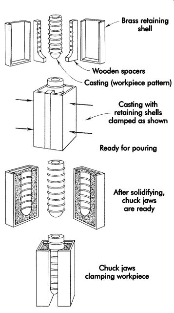
FIG. 122. Casting the vise jaws with low-tempera ture alloy.
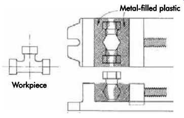
FIG. 123. Plastic vise jaws.
FIG. 122 shows the method of casting jaws for holding a nipple by pouring a low-temperature alloy around the workpiece, which is used as the pattern. Two wooden spacers locate the pattern and separate the cast jaw halves. The pattern is coated with a releasing agent for easy removal from the cast jaws. These jaws are then attached to the vise jaws.
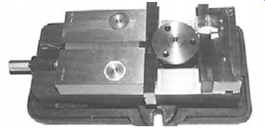
FIG. 120. Twin-Lock® workholding system.
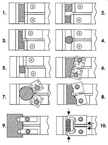
FIG. 121. Possible setups.
In the second method (FIG. 123), a plastic material is used. The material has a metal filler to give it more wear resistance and strength. The plastic is of putty-like consistency, and is placed on each jaw of the vise. The workpiece, a T-fitting in the example shown, again acts as the pattern.
Coated with a releasing agent, it is located and pressed into the plastic material on the two sides of the vise by closing the vise jaws. The plastic hardens within two hours to form two precise half-impressions of the workpiece, which make an excellent locating and holding arrangement.
The plastic material also may be used to locate and secure pins, bushings, and other details used in workholders.
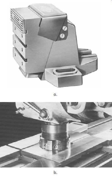
FIG. 124. Independent vise jaws.
Independent Jaws
Occasionally, independent vise jaws may be used as workholders for large or odd-shaped parts. In FIG. 124, these workholders are available in two general styles. The bigger of the two is useful for larger parts, while the smaller is well suited for edge gripping on thinner parts.
A third style of independent vise jaws is illustrated in FIG. 125. This style of vise is an
adjustable-range vise. Its jaws may be set at any convenient distance and are held in place with the rack gear. This style of vise is useful for machines with T-slots in the table since the rack must be located below the working surface of the vise.
Nonmechanical clamping
Sometimes it is impractical to hold a work piece by direct clamping pressure because of possible distortion or the size of the workpiece.
Magnetic, vacuum, and electrostatic workholders may be of value in such cases.
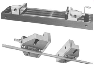
FIG. 125. Adjustable-range vise.
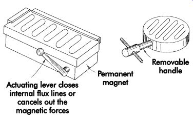
FIG. 126. Magnetic chuck.
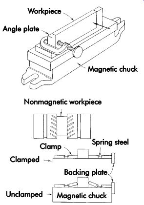
FIG. 127. Magnetic chuck and angle plate used as a workholder.
Magnetic chucks
Magnetic chucks are available in a variety of shapes. They can hold only ferrous workpieces unless intermediate mechanical workholders permit the holding of workpieces made of non magnetic material. Magnetic chucks are suitable for light machining operations such as grinding.
Strongly magnetic materials and better utilization of magnetic force permit their use for heavier operations, such as light milling and turning.
Magnetic chucks can be operated by permanent magnets or electromagnets powered by direct current. The gripping power attainable depends on the strength of the magnets and the amount of magnetic flux directed through the workpiece.
FIGs. 126 and 127 illustrate various magnetic chucks. A magnetic chuck is fast acting and, by holding a large surface of the workpiece, causes a mini mum of distortion. Magnetic chucks are available in rectangular shapes, circular shapes as rotary chucks, and as V-blocks. Magnetic chucks impart some residual magnetism to workpieces. This must be removed by demagnetizing if it interferes with proper functioning of the workpiece.
Vacuum chucking
Quite often, workpieces of nonmagnetic materials or special shapes and dimensions must be securely held flat without any mechanical clamping. An example might be a large flat plate.
In such cases, vacuum chucking may be the only practical holding method.
The basic principle of vacuum chucking is simple. On each square inch (square millimeter) of a 12 × 12-in. surface, as depicted in FIG. 128, a pressure of approximately 14.7 psi (101 kPa) is exerted by the atmosphere. This represents approximately 144 in. 2 × 14.7 psi = 2,116.8 lb or, in this example, lb/ft^2.
Part of this pressure is used by creating a vacuum in a closed chamber made up of the locating surface of the workpiece and mating surface of the workholder. At first, pressures on the outside and inside of the chamber are equal. As a vacuum is produced inside the chamber, the outside pressure holds the workpiece against the locating surface (FIG. 128). FIG. 129 illustrates a typical vacuum chuck. An O-ring seal laid in a groove around the chucking area creates the closed chamber to be evacuated. Holes and a grid of small connecting channels in the chucking surface assist in the speedy creation of the needed vacuum.
Electrostatic chucks
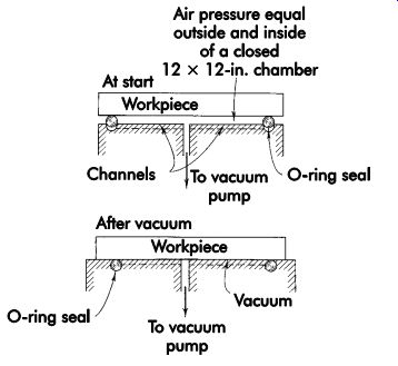
FIG. 128. Vacuum-chucking principle (12 × 12-in. sealing area).
The attraction of electrically opposite charged parts can hold flat or flat-sided workpieces that cannot be magnetized. Electrostatic chucks (Fig. 130) can hold any electrically conductive material. Glass, ceramics, and plastics also may be held by flash metal plating on one flat side to provide a suitable electrical contact.
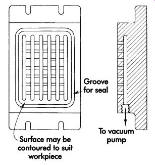
FIG. 129. Vacuum chuck.
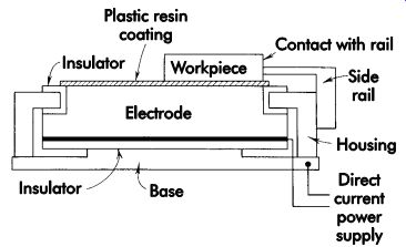
FIG. 130. Electrostatic chuck.
Power clamping
Power clamping devices are frequently used for applications where speed and uniform clamping pressures are important considerations. FIG. 131 shows how a typical power clamping sys tem is constructed. Power clamps normally are operated by hydraulic or pneumatic pressure, or a combination of both. FIG. 132 shows several typical setups for power clamping.
One problem in using any power clamping system is the basic law of "no hydraulic pres sure-no clamping pressure." If any clamping element leaks, or is disconnected, pressure is lost and the clamps loosen. One system of components that uses a mechanical locking principle in combination with a pressurized hydraulic system is the Stay-Lock® clamping system (FIG. 133). These clamps are built using a mechanical lock activated by hydraulic pressure. Once locked, the hydraulic pressure and hoses may be removed and the clamps stay locked firmly against the part.
The locking action of the clamping system is similar to a wedge-action clamp. Working on an inclined plane principle, this locking action operates in much the same way as a tapered shank drill. The basic operation of this clamp is illustrated in FIG. 134. In use, the piston is driven to one side of the clamp body by hydraulic pressure. The locking angles on the piston and locking pin engage and lock together.
This provides a mechanical lock. Thus, once the clamp is activated, the hydraulic connections can be removed and the clamp will not loosen.
The clamp is released by switching the hydraulic hoses to the release port. The pressure then drives the piston back off the locking pin.
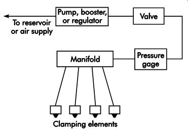
FIG. 131. Power clamping.
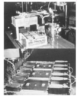
FIG. 132. Typical setups for power clamping.
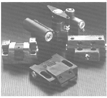
FIG. 133. Stay-Lock® clamping system.
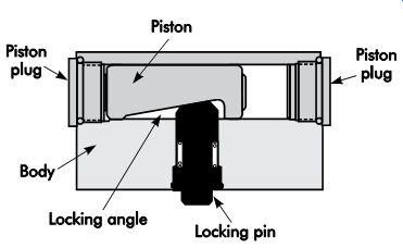
FIG. 134. Locking action.
Multiple-part clamping
When designing tools for large production runs, it is often desirable to machine more than one part at a time. In these cases, jigs and fixtures should be designed to permit multiple-part clamping.
The two principal points to remember when de signing workholders for multiple clamping are: (1) the clamping pressure must be equal on all parts, and (2) the tool should have a minimum number of operating points. In FIG. 135, a little fore thought and ingenuity make it possible to clamp almost any part in a multiple-part workholder.
Jig and Fixture Construction Principles
Every jig and fixture must be constructed properly to function as intended. The degree of accuracy and durability of the workholder is directly related to the way the tool is constructed.
Tool Bodies
Tool bodies are the major element of jigs and fixtures. They form the general size and shape of the tool, as well as provide the mounting surfaces for locators, supports, and workholding devices. The three principal types of tool bodies are welded, cast, and built-up (FIG. 136).
Cast
Cast tool bodies normally are made from cast aluminum, cast iron, or cast epoxy resin. These tool bodies are well suited for permanent, high volume production workholders. The principal advantages in using cast tool bodies include: stability and vibration dampening, good material distribution, and reductions in machining time. But cast tool bodies normally cost more to make since a pattern must be made for each tool.
Another disadvantage of cast tool bodies is the long lead-time requirement between design and fabrication of the tool.
Welded
Welded tool bodies normally are made from any weldable materials, such as steel, aluminum, magnesium, etc. This type of tool body can be easily fabricated with minimum lead time.
Welded tool bodies are strong, rigid, and easily modified when required. The major disadvantage of this type of tool body is the additional machining time required to repair and remove heat-distorted areas.
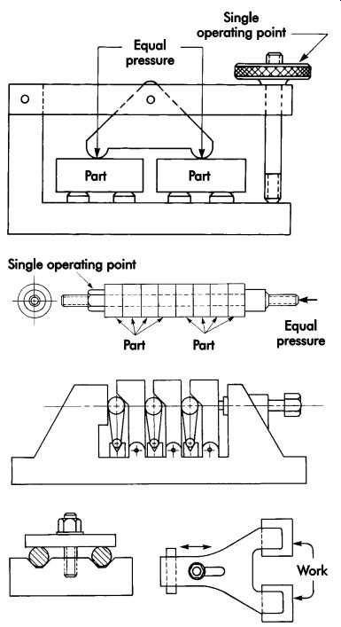
FIG. 135. Multiple-part clamping.
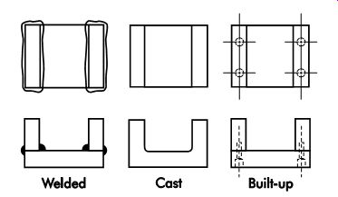
FIG. 136. Three types of tool bodies.
Built-up
Built-up tool bodies are made from a wide variety of different materials. Steel, aluminum, cast iron, wood, and epoxy resins are commonly used for built-up tool bodies. They are the most versatile and frequently used type for general jig and fixture work. Built-up tool bodies are inexpensive, easily modified, and require less machining after assembly than cast or welded tool bodies. This type of tool body normally uses dowel pins and socket-head cap screws to align and fasten each tool member.
Tooling Materials
In addition to fabricating tool bodies, many different tooling materials are used for locators, supports, or other jig and fixture elements. To keep the cost of a tool to a minimum, the tool designer should be familiar with the wide variety of preformed materials available.
Precision-ground Materials
Precision-ground materials are available in many shapes and sizes. The two primary variations are ground flat stock and drill rod. These materials are commercially available in either standard or oversized lengths of 18-36 in. (457-914 mm). Precision-ground materials are normally available in low-carbon and high-car bon steel, and oil-hardening and air-hardening tool steel. The tolerance values of these materials vary with the size and shape of the burr, but they normally are ground to within a few thousandths of an inch (?m) accuracy.
Aluminum Tooling Plate
Aluminum tooling plate, like precision-ground materials, is available in many sizes and shapes.
The major advantage to using this material is the close tolerance of the finished stock. Many times, tools assembled from these materials require no finish-machining prior to use.
Precast Bracket Materials
Precast bracket materials are commercially available in several shapes and sizes as illustrated in FIG. 137. These materials generally are made from either cast iron or cast aluminum and available in lengths of 18-36 in. (457-914 mm). Precast bracket materials frequently are used for locators, supports, or complete tool bodies.
The principal advantage to using these sections is the ease with which tools can be made using the convenient forms and shapes available.
Structural Sections
Structural sections are another type of material sometimes used for workholder components.
These sections are available in several different shapes and lengths of up to 16 ft (4.9 m) (FIG. 138). This makes structural sections useful for large or oversized workholders. The most common material used for these structural sections is low-carbon steel, but those made from aluminum or magnesium are also available. Structural sections normally are made by rolling. Thus they are not suitable for close-tolerance specifications unless machined. Nevertheless, these sections are versatile and will suit a wide range of tooling applications.
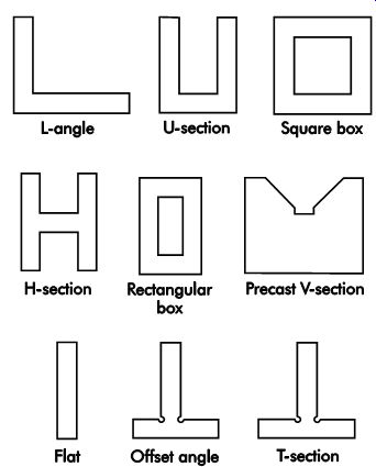
FIG. 137. Precast bracket materials.
Fasteners
Almost every jig and fixture uses some type of fastener to align and hold the various members and components in their proper position and relationship. The specific type of fastener used to assemble a particular workholder normally is determined by the joint and required tolerance of the assembled parts. The following sections describe fasteners that are commonly used for jig and fix ture work, and their preferred applications.
Screws and Bolts
Screws and bolts are the most common types of fastening devices used to construct assembled workholders. The principal difference between these fasteners is the method used to hold the assembled parts together. Screws normally are driven by their heads and turned into threaded holes. Bolts, on the other hand, are installed through holes and held in place with a nut.
The most common type of screw used for jig and fixture work is the socket-head cap screw (FIG. 139). In addition, variations of the socket-head cap screw (FIG. 140) also are frequently used to assemble workholders. The principal type of bolt used with jigs and fixtures is the T-bolt (FIG. 141). These bolts primarily secure the workholder to the machine table.
Other types of bolts include those with hex and square heads, and studs.
Nuts, Washers, and Inserts
Nuts, washers, and inserts are used for some workholder designs. The most commonly used nuts are hardened hex, check, T-slot, acorn, flange, and coupling. FIG. 142 illustrates a few of these types. The most frequently used washers are plain flat washers, self-aligning washer sets, C-washers, and swinging C-washers (FIG. 143). Thread inserts (FIG. 144) also are used for some applications. These inserts are available in several styles. All serve basically the same purpose-to provide a replaceable thread in an area where threads will not hold up well, such as in plastic or soft metals, or places where frequent installation and removal of the threaded fastener would rapidly wear out a normal thread.
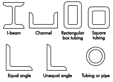
FIG. 138. Structural sections.
FIG. 139. Socket-head cap screw.
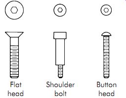
FIG. 140. Variations of the socket-head cap screw.
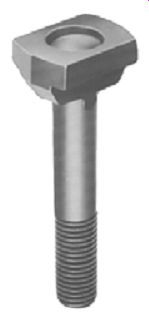
FIG. 141. T-bolt.
Dowels and Pins
Dowels and pins are another form of fastener often found in workholders. Unlike screws and bolts, these fasteners are intended to align assembled components rather than secure them.
The most common type of pin used for alignment is the hardened-steel dowel pin (FIG. 145). Other variations include pull dowels for use in blind holes and roll pins. Roll pins frequently are used in place of dowel pins to eliminate the need to ream the mounting holes. However, these pins should only be used in areas where the assembled tolerance will permit some variation in the position of the assembled members.
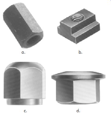
FIG. 142. (a) Hardened hex nut, (b) T-slot nut, (c) acorn nut, and (d) spherical
flange nut.
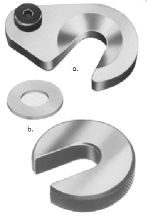
FIG. 143. (a) Swinging C-washer, (b) flat washer, (c) C-washer.
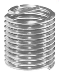
FIG. 144. Thread insert.

FIG. 145. Hardened-steel dowel pin.
Retaining Rings
Retaining rings (FIG. 146) are normally used for fastening in areas with a minimum amount of axial thrust against the fastener.
These fasteners are faster and easier to install than standard threaded fasteners and will work equally well for both internal and external applications.
Fixture Keys
Fixture keys, while not actually fastening devices, are an integral part of many workholders. They are used to locate a fixture to T-slots in a machine tool (typically a milling machine). The two principal styles of fixture keys used for jigs and fixtures are the plain, or standard, and interchangeable (FIG. 147). Generally, an interchangeable style fixture key is easier to use and permits a single set of keys to be used for several workholders. How ever, standard keys are well suited for permanent installations.
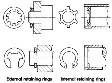
FIG. 146. A variety of retaining rings.
Ball Lock® Mounting System
Many different methods are used to mount workholders to machine tools during machining. The main problem has been finding a way to reduce the needed setup time. One method of reducing this time is to use the Ball Lock mounting system. These units accurately position and securely contain the workholder on the machine table. In FIG. 148, this mounting system has three major parts, a flanged shank, a liner bushing, and a Ball Lock bushing. In use, the bushings are installed in both the workholder and machine base or mounting subplate. The flanged shank then is installed through the liner bushing into the bushing and tightened down using the socket head cap screw (FIG. 149).
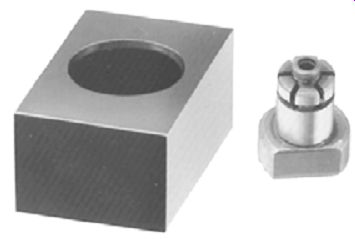
FIG. 147. (a) Square fixture key, (b) single fixture key.
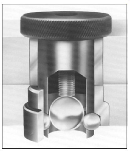
FIG. 148. Ball Lock® mounting system.
The operation of the Ball Lock unit is quite simple. As the socket head cap screw in the head of the flanged shank is tightened, a large ball is forced against three smaller balls. This action moves the three locking balls outward in their sockets against the conical sides of the Ball Lock bushing. When the three balls contact the conical area of the Ball Lock bushing, they both center the flanged shank and apply a downward force against the shank, locking it against the fixture base. Rather than locating on the cylindrical diameter of the shank, the actual location is
achieved by the locking balls against the conical area of the Ball Lock bushing.
Other Refs.
The Society of Manufacturing Engineers (SME) has produced an introductory Workholding video (approximately 30 minutes, order code: DV09PUB6, visit online: www.sme.org ) which relates directly to this section's content.
The video examines the principles and concepts inherent to all workholding. In addition, it explores the various workholding options for milling and machining centers and lathes. Featured are: requirements for workholding; methods for high- and low-volume parts; machining center workholding; and the use of chucks, collets, and other lathe workholding devices.
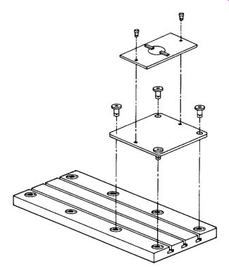
FIG. 149. Installation of bushings and flanged shank.
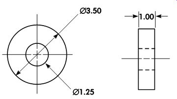
Figure A.
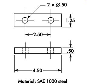
Figure B.
QUIZ
1. What are the basic elements that make up a workholder?
2. What are the three fundamental categories of workpiece location?
3. Design a locating system to locate and sup port the part shown in Figure A.
4. What is the simplest and most basic type of location?
5. What types of material are used for cast, nest locators?
6. Design a locating method for the part shown in Figure B using a diamond pin to restrict radial movement.
7. How should clamping elements be positioned with relation to the workpiece?
8. What is the simplest and least expensive type of clamping device used for jigs and fixtures?
9. What type of nonmechanical clamping device is well suited to hold nonferrous parts?
10. What type of tool body is most common?
11. What are diamond locator pins? How are they used?
12. Discuss repetitive nesting of workpieces in a fixture or jig.
13. What are the common methods of locating from circular/cylindrical surfaces?
14. List the rules that should be followed when designing clamps for fixtures. Explain them in your own words.
15. List at least seven standard commercial pre-machined/formed sections or forms (tooling plate) available to the tool designer.
Indicate at least three advantages of using these pre-machined sections.
Home PREV. NEXT Article Index top of page