AMAZON multi-meters discounts AMAZON oscilloscope discounts
The physics of metal cutting provide the theoretical framework by which all other elements of cutting tool design must be examined. Workpiece materials range from a very soft, buttery consistency to very hard and shear resistant. Each workpiece material must be handled by itself; the amount of broad information applicable to each material is reduced as the distinctions between workpiece characteristics increase. Not only is there a vast diversity of workpiece materials, but a large variety of tool shapes and compositions as well.
The tool designer must match many variables to provide the best possible cutting geometry.
Trial and error once was normal for this decision, but today, with the ever-increasing variety of tools, it is far too expensive. The designer must develop expertise in applying data and making comparisons on the basis of others' experience.
FORM AND DIMENSION
The primary method of imparting form and dimension to a workpiece is by the removal of material using edged cutting tools. An oversize mass is literally carved into its intended shape.
The removal of material from a workpiece is termed generation of form by machining, or simply machining.
Form and dimension also may be achieved using a number of alternative processes, such as hot or cold extrusion, and sand, die, and precision casting. Sheet metal can be formed or drawn by the application of pressure. In addition to ma chining, metal removal can be accomplished by chemical or electrical methods. A great variety of workpieces may be produced without resorting to a machining operation. Economic considerations, however, usually dictate form generation by machining, either as the complete process or in conjunction with another process.
Elements of Machining
Material removal by machining involves the interaction of five elements:
1. cutting tool,
2. toolholding and guiding device,
3. workholder,
4. workpiece, and
5. machine.
The cutting tool may have a single or many cut ting edges. It may be designed for linear or rotary motion. The geometry of the cutting tool depends on its intended function. The tool-holding device may or may not be used for guiding or locating.
Toolholder selection is governed by tool design and the intended function.
The physical composition of the workpiece greatly influences the selection of machining method, tool composition and geometry, and rate of material removal. The intended shape of the workpiece also influences the selection of machining method and choice of linear or rotary tool travel. To a great extent, the composition and geometry of the workpiece determines work holder requirements. Workholder selection also depends on forces produced by the tool on the workpiece. The work-holder must hold, locate, and support the workpiece. Tool guidance may be incorporated into the workholding function.
Successful tool design for material removal re quires, above all else, a complete understanding of cutting tool function and geometry. This knowledge enables the designer to specify the correct tool for a given task. The tool, in turn, governs the selection of toolholding and guidance methods. Tool forces govern selection of the work holding device. Although the process involves the interaction of the five elements, everything begins with and is based on what happens at the point of contact between the workpiece and cutting tool.
BASICS OF METAL CUTTING
Cutting tools are designed with sharp edges to shear the workpiece and minimize rubbing contact. Variations in the shape of the cutting tool influence tool life, the surface finish of the workpiece, and the amount of force required to shear a chip from the parent metal. Various angles on a tool comprise what is often termed the tool geometry:
• the surface that the chip flows across is called the face or rake face;
• the surface that forms the other boundary of the wedge is called the flank;
• the rake angle is the angle between the tool face and a line perpendicular to the cut workpiece surface, and
• the relief or clearance angle is the angle be tween the tool flank and the cut workpiece surface.
Orthogonal and Oblique Cutting
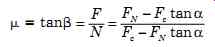
Orthogonal cutting ( FIG. 1) is defined as two-dimensional cutting in which the cutting edge is perpendicular to the direction of motion relative to the workpiece, and the cutting edge is wider than the chip. Oblique cutting is used if the direction of cutting is not perpendicular to the cut ting edge. FIG. 2 shows a three-dimensional case requiring more cutting angles to define the tool. The effects on three-dimensional cutting must be described on the basis of the effective rake angle in the direction of chip flow.
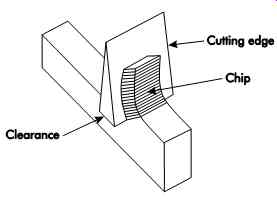
FIG. 1. Orthogonal cutting.
CHIP FORMATION
The majority of metal-cutting operations involve the creation of chips, or waste, from the workpiece. Chip formation involves three basic requirements. There must be:
1. a cutting tool harder and more wear-resistant than the workpiece material;
2. interference between the tool and workpiece as designated by the feed and depth of cut; and
3. a relative motion or cutting velocity between the tool and workpiece with sufficient force to overcome the resistance of the workpiece material.
As long as these three conditions exist, the portion of material being machined that interferes with free passage of the tool will be displaced to create a chip. Many possibilities and combinations exist that may fulfill such requirements.
Variations in tool material and tool geometry, feed and depth of cut, cutting velocity, and workpiece material affect not only chip formation, but also cutting force, horsepower, and temperatures; tool wear and life; dimensional stability; and the quality of the newly created surface. The inter relationship and interdependence among these manipulating factors constitute the basis for the study of machinability-a study that has been popularly defined as the response of a material to machining.
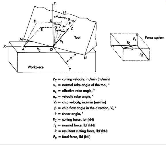
FIG. 2. Oblique cutting.
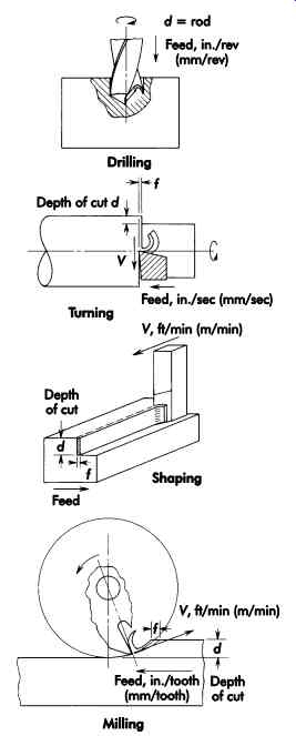
FIG. 3. Examples of feed depth and velocity relation ships for several
chip-formation processes.
Types of Chips
FIG. 3 illustrates the necessary relation ship between cutting tool and workpiece for chip formation in several common machining processes. Although it is apparent that different shapes and chip sizes may be produced by each of the basic processes, all chips, regardless of process, are usually classified according to their general behavior during formation.
When a brittle material like cast iron or bronze is cut, it is broken along the shear plane. The same may happen if the material is ductile and the friction between the chip and tool is very high. The chips come off in small pieces or segments, and are pushed away by the tool. A chip formed in this way is called a type I, discontinuous, or segmental chip. A ductile material, cut optimally, is not broken up but comes off like a ribbon, as shown in FIG. 4a. This is known as a type II or continuous chip. An evident line of demarcation separates the highly distorted crystals in the chip from the undistorted parent material.
Built-up Edge
In the formation of continuous chips, consideration of chip flow along the face of the tool is of prime importance. If the friction force resisting the passage of the chip along the tool face is less than the force necessary to shear the chip material, the entire chip will pass off cleanly (FIG. 4a). This ideal case of chip formation may be approached but is seldom realized. It is generally associated with materials of high strength and low work-hardening capacity, and with low coefficients of friction-factors that lead to large shear angles.
The mechanism for built-up edge formation is not completely understood, but there seems to be a correlation with temperature and, thus, a correlation with cutting speed. Often, a built-up edge will not appear at very low cutting speeds, but will start to appear as the cutting speed is increased, peaking and starting to decrease as the cutting speed is further increased. Higher cutting speeds are favored if there are no adverse effects.
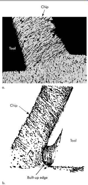
FIG. 4. (a) Photomicrograph of a partially formed continuous chip. AISI
1015 steel cut at 24 ft/min (7.3 m/min) with cutting fluid composed of water
and 1% rust inhibitor. (b) Drawing of a photomicrograph of a continuous chip
and tool with a built-up edge.
In most cases, it is nearly impossible to prevent some amount of seizure between the chip and the tool face. Unless surfaces are perfectly flat, contact is made along the high spots over only a fraction of the total area. As the chip passes over the tool face, cutting forces give rise to extremely high unit pressures, which are sufficient to form pressure welds. If these welds are stronger than the ultimate shear strength of the material, that portion of the chip welded to the tool shears off as the chip is displaced and becomes what is called a built-up edge. Continuous chips with built-up edges are illustrated in FIG. 4b.
The built-up edge is common to most metal cutting operations and particularly evident in machining aluminum and some stainless steels.
The edge builds up to a point where it eventually breaks down, part of it going off with the chip, and part of it being deposited on the work surface. This characteristic occurs at rapid intervals.
When steel is cut, a continuous chip is usually formed, but the pressure against the tool is high and the severe action of the chip quickly rubs the natural film from the tool face. The freshly cut chip and the newly exposed material on the face of the tool have an affinity for each other, and a layer of highly compressed material adheres to the face of the tool. Any change in cutting conditions that reduces or eliminates the built-up edge will usually improve surface quality. Built up edge affords some protection to the cutting edge to reduce wear, and a small amount may be desirable. The problem then becomes one of size control through the effects of the various manipulating factors.
MECHANISM OF CHIP FORMATION
Observations during metal cutting reveal several important characteristics of chip formation. Those observations include:
• the cutting process generates heat;
• the thickness of the chip is greater than the thickness of the layer being cut;
• the hardness of the chip usually is much greater than the hardness of the parent material; and
• the above relative values are affected by changes in cutting conditions and in the properties of the material to be machined to produce chips that range from small lumps to long continuous ribbons.
These observations indicate that the process of chip formation is one of deformation or plastic flow of the material, with the degree of deformation dictating the type of chip that will be produced.
Plastic flow takes place by means of a phenomenon called slip, along what are referred to as slip planes. The capacity for plastic flow depends on the number of slip planes available. The number of planes, in turn, depends on the crystal lattice structure of the material and prior treatment.
When the resisting stresses in a material exceed its elastic limit, a permanent relative motion occurs between the adjacent slip planes most favorably oriented in the direction of the applied force. Once this motion or slip takes place, these particular planes are strengthened and resist further deformation in preference to other, now weaker, planes that are available. This strengthening is called work or strain hardening, and is characteristic of all steels but most dramatically exhibited in stainless steels.
As the tool advances into the workpiece, frictional resistance to flow along the tool face and resultant work hardening cause deformation to take place ahead of the tool along a shear plane.
This plane extends from the vicinity of the cut ting edge toward the free surface of the workpiece at some shear angle, θ, as illustrated in FIG. 5. If the workpiece material is brittle and has little capacity for deformation before fracture, when the fracture shear stress is reached, separation will take place along the shear plane to form a segmental chip. Ductile materials, however, contain sufficient plastic flow capacity to deform along the shear plane without rupture. Strain hardening permits a transfer of slip to successive shear planes, and the chip tends to flow in a continuous ribbon along the face of the tool and away from the work surface. The chip is highly worked and much harder than the material from which it is taken. FIG. 6 illustrates the relationship of all forces represented by the force R acting at the edge of the tool with the components in their respective positions.
The effect of a change in shear is shown in FIG. 5. For a given depth of cut, a smaller shear angle, θ2, causes a greater chip cross-section and, therefore, greater distortion than in the case of the larger shear angle θ1. For a given material, the shear angle is a function of the tool rake angle and the coefficient of friction along the tool face. Materials that have fewer slip planes and low work-hardening capacity generally show higher shear angles than the more ductile materials, and have a lower ratio of chip thickness to un deformed chip thickness. Under ideal conditions, this ratio will approach 1.5 and can be checked to a rough extent by measuring the thickness of the chip and comparing it to the feed rate.
Effect of Manipulating Factors
Certain manipulating factors provide some control of the metal-cutting characteristics.
When studying various examples, keep in mind the relationship between tool, chip, and surface appearance. The size and the degree of the chip's brittleness may be a good indication of the severity of the cutting operation. The back of the chip, which is in contact with the tool face, gives a fairly good indication of the built-up edge condition. In the absence of a built-up edge, the back of the chip should be clean, smooth, and highly burnished. The workpiece surface should be correspondingly good. As the size of the built up edge increases, more and more markings are evident on the chip. Generally, the workpiece is affected in the same manner.
Velocity
Velocity refers to the speed at which the cut ting edge moves through the workpiece material.
This is slightly different from speed in terms of revolutions per minute (rpm) because the velocity is a function of the rate at which the workpiece (or cutting tool) is turning (rpm) and the radius at which the cutting edge is located. Velocity affects temperature, which in turn affects the cutting process. At low velocities, the temperature at the tool point is below the recrystallization temperature of the material. As a result, work hardening in the chip is retained and the workpiece material is not softened due to failure to reach the yield strength temperature of the material. If the velocity in creases to the point where the cutting temperature is above the yield strength temperature of the material, chip material at the interface tends to soften and machine much more efficiently. Higher shear angles occur at higher velocities, and an ideal chip thickness of 1.5 times the feed can be approached. As mentioned, built-up edge formation is less at higher velocities. High-speed machining takes advantage of all of these factors. However, excessive velocity that results in excessive heat generation and tool wear will cause the tool to fail rapidly. Of all the manipulating factors, speed generally has the greatest effect on tool life.
The form or shape of chips at high velocities can be troublesome on ductile materials. The reduced resistance to chip flow and resultant increase in shear angle gives a thinner, less distorted chip, but one that becomes longer and straighter as velocity increases. Chip grooves specifically designed for thin chips can be employed to deal with this problem.
Size of Cut
Changes in the size of cut effectively change the cross-sectional area of chip contact (Figures 7a and b). How this area is changed determines the effect on the cutting process. An increase in the depth of cut for a constant feed merely lengthens the contact, but does not change the thickness, so the force per unit length remains the same. However, an increase in feed for a given depth widens the area of contact and changes the force per unit length. This results in greater chip distortion and reduced tool life, although increased feed reduces the machining cycle.
Several factors affect surface quality to a greater degree than may be predicted. Lack of rigidity will permit greater deflections as a result of higher forces. Increases in feed and depth of cut then may cause chatter, poor surface quality, and loss of dimensional stability. Deep turning cuts on relatively small diameters have a greater percentage of change in velocity along the length of the cutting edge. This might result in erratic tool life behavior with poor surface quality.
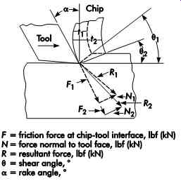
FIG. 5. Effect of friction force on shear angle and the amount of chip
distortion. Force polygons show effect of friction force on magnitude and
direction of resultant force.
The effect upon the chip is also much more pronounced with increases in feed than in depth.
Because of the greater distortion at high feed rates, chips tend to break up more readily. Chip control is essential for operator safety, since long, continuous chips can wrap around the rotating part and become dangerous.
Tool Geometry
For specified cutting conditions, changes in tool geometry have two direct effects on chip formation:
1. effect upon shear angle, and
2. effect upon chip thickness.
The two are related in that a change in one usually affects the other. The effects of changes in rake angles are shown in FIG. 8. Lower rake angles decrease the shear angle, cause greater chip distortion, and increase the resistance to chip flow. Lower rake angles (negative) produce rougher and more work-hardened surfaces. At low or negative rake angles, the chip is so highly distorted that it facilitates chip control by breaking the chip into six short lengths.
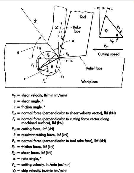
FIG. 6. Force and velocity system of a cut.
Selection of Tool Material
Cutting tool materials differ in their ability to sustain high cutting velocities. For example, high-speed steel (HSS) is less able to sustain the forces and temperatures generated at high cut ting velocities than carbide. The effect of high velocity on the cutting process and temperature generation has already been described. Another factor when selecting a cutting tool material is the coefficient of friction between the chip and tool material. Usually, this is of little consequence with HSS tools because the coefficient of friction does not change appreciably among the various grades. Sintered carbide, cermet, and ceramic tools are made with different compositions and may behave quite differently for similar cutting conditions.
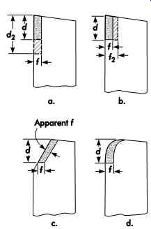
FIG. 7. Effect of size of cut and changes in tool geometry on chip thickness:
(a) change in depth, (b) change in feed, (c) effect of side-cutting-edge
angle, and (d) effect of nose radius.
Crosshatched portions represent an increase in contact area.
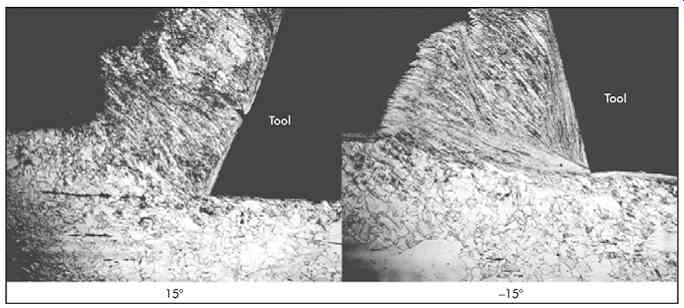
FIG. 8. Photomicrographs showing the effect of rake angle on shear angle,
chip distortion, built-up edge, and work hardening of a machined surface.
Shaper tools were set for same depth of cut. Apparent difference in depth
is due to higher separating force and greater tool deflection with a negative
rake tool. Work material is 304 stainless steel.
Cutting Fluids
Ideally, if a cutting fluid provides lubrication between the chip and the tool, the coefficient of friction will be reduced and the shear angle increased. However, effective lubrication in this region may be difficult to achieve, except possibly at very low cutting speeds or higher application pressures. The effects of lubricant vary with cut ting conditions and work materials. At high speed, fluids act principally as coolants but may effectively lubricate the tool-chip interfacial zone. This provides more efficient machining, which often results in increased tool life and improved surface finish. Constant, even flow is essential when cut ting fluids are applied with carbide tools to prevent thermal shocking and resultant fracture.
Workpiece Materials
Brittle materials form discontinuous chips and can be machined with neutral rake (for ex ample, rake flat top inserts with no chip groove pressed in). Cutting forces are usually lower and tool life is longer than for a ductile material of corresponding strength because of generally large shear angles and lower resistance along the tool face.
Ductile materials produce continuous chips.
Continuous chips can be dangerous to operators and machines, so the problem has to be solved.
With low friction and high cutting velocities, particularly with materials of low work-hardening capacity, a thinner, less distorted chip is produced. For inserts, pressed-in chip grooves are required for low feed rates to break up the chip. High frictional resistance to flow, low shear angles, and materials of high work-hardening capacity are associated with large distortions during cutting, and breaking up chips is not such a problem. The addition of lead, sulfur, and phosphorus to low-carbon steels helps break up chips, reduces the built-up edge, and improves surface quality.
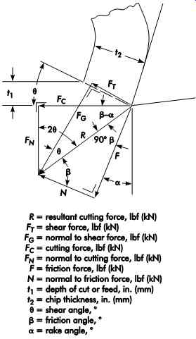
FIG. 9. Forces acting on a continuous chip in orthogonal cutting.
CUTTING FORCES
The forces arising from orthogonal cutting are shown in FIG. 9. Fc and FN are the cutting and normal force, respectively. These components of the resultant force, R, can be measured by means of a dynamometer,
 (eq.1)
Then, FT = Fc
cos? - FN sin? where:
? = coefficient of friction
? = friction angle, ° F = force required to overcome friction between chip and face of tool, lbf (kN)
FN = normal force, lbf (kN) FC = cutting force, lbf (kN)
? = rake angle, ° FT = shear force, lbf (kN)
? = shear angle, ° FT cannot be calculated from the static mechanical properties of the material cut, since the strain rate encountered in metal cutting is much greater than in any conventional test. The shear angle ? must be determined before the shearing force and shear flow stress can be determined from Fc and FN. One method of approximating the shear angle is by measuring the thickness of the chip. Optimum shear angles occur when ? is in the range of 1.5. (eq. 2)
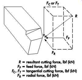
FIG. 10. Three components of cutting force.
FIG. 11. Three components of cutting force through tool life.
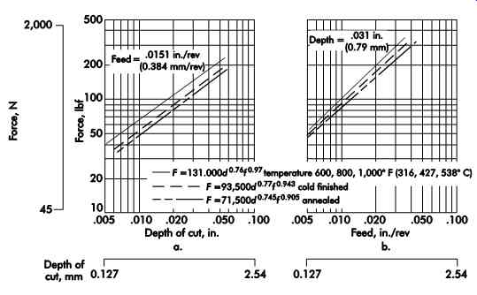
FIG. 12. (a) Cutting force vs. depth of cut. Tool material-high-speed steel,
geometry-6, 11, 6, 6, 6, 15, .01, work material-SAE 1045 steel. (b) Cutting
force vs. feed, depth-.031 in.
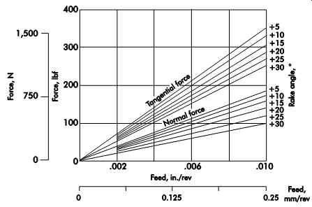
FIG. 13. Effect of feed on tangential and normal cutting forces for a range
of rake angles when turning nickel steel.
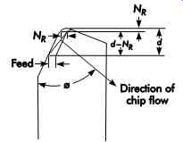
FIG. 14. Approximate chip flow direction.
Power Requirements
[...]
Specific Power Consumption or Unit Horsepower
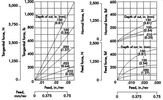
FIG. 15. Effect of feed on tangential feed and normal forces for various
depths of cut. Tool material-high-speed steel, tool shape-8, 14, 6, 6, 6,
15, 3/64, work material-SAE 3135 steel, annealed, cutting speed-50 ft/min
(15.2 m/min) (dry).
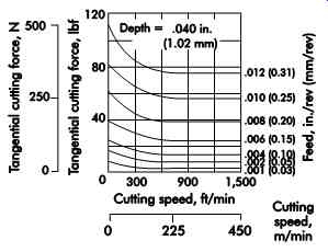
FIG. 16. Effect of cutting speed on cutting force for various feeds when
cutting bronze with a tungsten car bide tool. Depth of cut-.040 in. (1.02 mm).
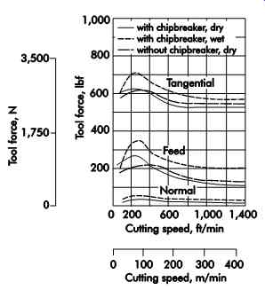
FIG. 17. Effect of cutting speed on tool forces. Tool material-tungsten
carbide, tool shape-10, 10, 8, 8, 7, 0, .015, work material-AISI C 1118 steel,
depth of cut-.150 in. (0.38 mm).
Tool Wear
For the sake of recognition and understanding the fundamentals of metal cutting, the effects of changes in manipulating factors have been described without regard to their influence on such criteria as tool wear and tool life.
Yet, there is no known tool material that can completely resist contact and rubbing at high temperatures and high pressures without some changes from its original contours over time.
It becomes necessary, therefore, to think of the effect of the manipulating factors not only on the cutting process itself, but also on the performance of the cutting tool, which may, in turn, itself affect the cutting process.
Tool Failure
Failure of the cutting tool occurs when it is no longer capable of producing parts within required specifications. The point of failure, together with the amount of wear that determines it, is a function of the machining objective. Surface quality, dimensional stability, cutting forces, cut ting horsepower (kW), and production rates may alone, or in combination, be used as criteria for tool failure. It may, for example, take very little wear to affect surface quality, although the tool itself could continue to remove metal with little if any loss of efficiency. In contrast, only a few thousandths of an inch of wear on a wide-form tool might cause such a large increase in thrust or feeding forces that it would result in a loss of dimensional stability, or require excessive power in addition to a loss of surface quality.
Types Of Tool Wear
Tool failure is associated with some form of breakdown of the cutting edge. Under proper operating conditions, this breakdown takes place gradually over a period of time. In the absence of rigidity, or because of improper tool geometry that gives inadequate support to the cutting edge, the tool may fail by mechanical fracture or chipping under the load of the cutting forces.
This is not truly a wear phenomenon-it can be eliminated or at least minimized by proper design and application.
As a result of direct contact with the work material, there are three major regions on the tool where wear can take place: face, flank, and nose ( FIG. 18).
Face Wear
The face of the tool is the surface over which the chip passes during its formation. Wear takes the form of a cavity or crater, originating not along the cutting edge but at some distance away and within the chip contact area. As wear progresses with time, the crater gets wider, longer, and deeper, and approaches the edges of the tool.
(coming soon) Table 1. Power consumption values for various materials
Crater wear usually is associated with ductile materials that give rise to continuous chips. If crater wear is allowed to proceed too far, the cutting edge becomes weak as it thins out and suddenly breaks down. Usually, there is some preliminary breakthrough of the crater at the nose and periphery prior to total failure of the cutting edge.
These preliminary breaks serve as focal points for the development of notches along the flank. In general, crater wear develops faster than flank wear on ductile materials, and is the limiting factor in determination of tool failure.
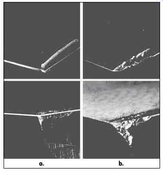
FIG. 18. Representative wear patterns on face, flank, and nose of cutting
tool, typical of a chip-removal pro cess on ductile materials. Crater on
face of tool in (a) started well back of the cutting edge. In (b) crater
wear had progressed to point where the weak cutting edge broke down under
cutting forces.
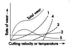
FIG. 19. Relative effects of various causes of tool wear: (1) abrasive
wear, (2) plastic deformation of the cutting edge, (3) chemical decomposition, (4) diffusion, (5) welding of asperities.
Flank Wear
Although crater wear is most prominent in the machining of ductile materials, flank wear always is present, regardless of work and tool material, or even cutting conditions. The flank is the clearance face of the cutting tool, along which the major cutting edge is located. It is the portion of the tool in contact with the work at the chip separation point, and it resists the feeding forces. Because of the clearance, initial contact is made along the cutting edge. Flank wear begins at the cutting edge and develops into a wider and wider flat of increasing contact area called a wear land.
Materials that do not form continuous chips promote little if any crater wear, and flank wear becomes the dominant factor in tool failure. In the case of most form tools and certain milling cutters, the wear land is in direct contact with the finished surface, and usually becomes the basis for failure even on ductile materials, particularly if surface finish specifications are the controlling factors in the process. Quite often, flank wear is accompanied by a rounding of the cutting edge, particularly when machining abrasive materials.
This results in large increases of cutting and feeding forces that, if carried too far, could lead to tool fracture.
Nose Wear
Nose wear is similar to and often considered a part of flank wear, but can be considered separately.
Nose wear sometimes proceeds at a faster rate than flank wear, particularly when working on abrasive materials and using small nose radii. In finish turning operations, for example, excessive wear will affect finished part dimensions as well as surface roughness. Where sharp corners are specified on the part drawing, the rounding or flattening of the nose can cause out-of-tolerance conditions long before flank wear itself becomes a factor.
mechanism of tool wear Evidence indicates that wear is a complex phenomenon influenced by many factors. The causes of wear do not always behave in the same manner, nor do they always affect wear to the same degree under similar cutting conditions.
The causes of wear are not fully understood, although various researchers have made great strides. Even though there is some disagreement regarding the true mechanisms by which wear actually takes place, most investigators feel that there are at least five basic causes of wear:
1. abrasive action of hard particles contained in the work material;
2. plastic deformation of the cutting edge;
3. chemical decomposition of the cutting tool's contact surfaces;
4. diffusion between the work and tool material; and
5. welding of asperities between work and tool.
The relative effects of these causes are a function of the cutting velocity or cutting temperatures and are shown in FIG. 19. Investigations have been made on other possible causes, such as oxidation and electrochemical reactions in the tool-work contact zone.
The most important factor influencing tool wear is cutting temperature. Of the five basic causes of wear, temperature has a considerable effect in all but one. Cutting temperatures are important for two basic reasons:
1. most tool materials show rapid loss of strength, hardness, and resistance to abrasion above some critical temperature, and
2. the rate of diffusion between work and tool materials rises very rapidly as the tempera ture increases past the critical mark.
Analytical and experimental methods have been used to show that the average peak temperatures at the tool-chip interface occur near the point where the chip leaves the tool surface ( FIG. 20). Crater wear appears greatest at this point. The relationship between the crater-wear rate and average tool-chip interface temperature is shown in FIG. 21. The rate of wear increases rapidly beyond a critical temperature. Flank temperatures were found to be maximum near the tool point as shown in FIG. 22.
The significance of temperature on wear is associated with the tool's material properties.
High-speed steel (HSS) tools begin to lose their properties very rapidly at approximately 1,100° F (593° C). Carbides show less drastic sensitivity to temperature up to about 1,600° F (871° C). Chemical decomposition and diffusion will not occur at any appreciable extent until critical temperatures are reached.
Abrasive Action
Wear by abrasive action may be partly explained by the fact that hard particles (sand inclusions, carbides, etc.) in the workpiece material literally gouge or dislodge particles from the tool, causing continuous wear under any cut ting condition. The rate of wear is dependent on the number, size, distribution, and hardness of the particles in the work material, as well as the hardness of the cutting tool and the work piece. At higher cutting speeds, even some of the softer constituents may contribute to the gouging action as a result of higher impact values and reduced tool resistance to abrasion.
Plastic Deformation of the Cutting Edge
Plastic deformation of the cutting edge is believed to take place at all ranges of cutting temperatures; it arises from the high unit pressures imposed on the tool. This results in a slight depression and bulging of the edge, similar to that shown in FIG. 23. The net effect is greater tool pressure and increased cutting temperature, resulting in further deformation and concluding in edge wipeout. This mode of failure is common when machining hardened materials at high speeds.
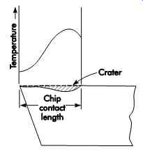
FIG. 20. Temperature distribution along tool-chip contact length.
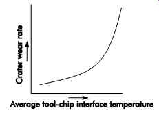
FIG. 21. Relationship between the rate of crater wear and average tool-chip
interface temperature.
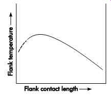
FIG. 22. Distribution of flank temperature along flank-work contact length.
Chemical Distortion of the Cutting Tool
Chemical distortion of the cutting tool occurs through localized chemical reactions at the tool-workpiece interface. These reactions are temperature-dependent and result in weakening the bond between minute tool segments and the segments surrounding them. This may occur either through formation of weaker compounds or, in the case of carbide tools, by dissolving action of the bond between the binder and individual carbide particles. As a result of this weakening effect, particles are pulled out from the main body of the tool by the chip or work as it moves past the contact surfaces. Once the critical tempera ture for this chemical action is reached, the rate of wear is relatively rapid.
Diffusion
Diffusion, a complex wear phenomenon between the work and tool, results in a rapid breakdown of the tool material once the critical temperature is reached. Much has yet to be learned about this cause of wear, but basically it involves a change of composition at the tool chip interface. There is an alloying effect that weakens the bond of tool particles and permits them to be pulled out by the chip as it sloughs off. Carbon transfer from the tool material to the workpiece is enhanced at higher temperatures and this greatly contributes to premature tool failure. Selection of a cutting tool material that is less susceptible to this transfer would allow machining at higher temperatures and speeds.
For example, cubic boron nitride (CBN) is used for machining hard ferrous materials for this very reason.