AMAZON multi-meters discounts AMAZON oscilloscope discounts
The machinery most closely associated with many cooling water supply systems consists of pumps and fans. In a modem process plant, machines can take on a variety of configurations and range from small "office-size" and inexpensive to extremely large and expensive. We have covered pumps in Section 7 and will, therefore, concentrate on cooling tower fans and their drive systems.
Mechanical draft towers use either single or multiple fans to provide flow of a known volume of air through the tower. Thus their thermal performance tends toward greater stability and is affected by fewer psychrometric variables than that of the atmospheric towers. The presence of fans also provides a means of regulating air flow, to compensate for changing atmospheric and load conditions, by fan capacity manipulation and/or cycling.
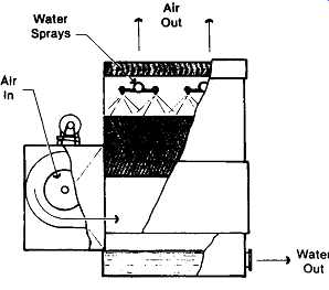
FIG. 1 Forced draft, counterflow, blower fan tower (The Marley Cooling Tower
Company)
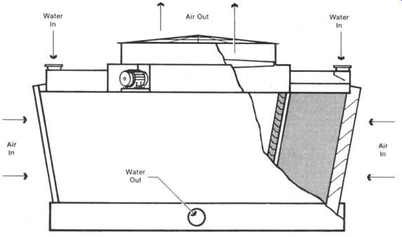
FIG. 2 Induced draft, crossflow, propeller fan tower. (The Marley Cooling
Tower Company)
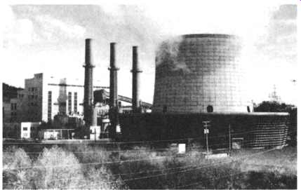
FIG. 3 Fan-assisted natural draft tower. (The Marley Cooling Tower Company)
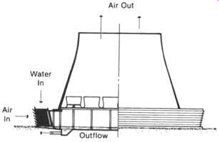
FIG. 4 Cutaway of fan-assisted draft tower. (The Marley Cooling Tower Company)
Mechanical draft towers are categorized as either forced draft ( FIG. 1), on which the fan is located in the ambient air stream entering the tower and the air is blown through, or induced draft ( FIG. 2), wherein a fan located in the exiting air stream draws air through the tower.
Forced draft towers are characterized by high air entrance velocities and low exit velocities. Accordingly, they are extremely susceptible to recirculation and are therefore considered to have less performance stability than the induced draft.
Furthermore, located in the cold entering ambient air stream, forced draft fans can become subject to severe icing (with resultant imbalance) when moving air laden with either natural or recirculated moisture.
Usually, forced draft towers are equipped with centrifugal blower type fans, which, although requiting considerably more horsepower than propeller type fans, have the advantage of being able to operate against the high static pressures associated with ductwork. Therefore, they can either be installed indoors (space permitting) or within a specially designed enclosure that provides significant separation between intake and discharge locations to miminize recirculation.
Induced draft towers have an air discharge velocity of from three to four times higher than their air entrance velocity, with the entrance velocity approximating that of a 5-mph wind. Therefore, there is little or no tendency for a reduced pressure zone to be created at the air inlets by the action of the fan alone. The potential for recirculation on an induced draft tower is not self-initiating and, therefore, can be more easily quantified purely on the basis of ambient wind conditions. Location of the fan within the warm air stream provides excellent protection against the formation of ice on the mechanical components. Widespread acceptance of induced draft towers is evidenced by their existence on installations as small as 15 gallons per minute (gpm) and as large as 700,000 gpm.
Hybrid draft towers ( FIG. 3) can give the outward appearance of being natural draft towers with relatively short stacks. Internal inspection ( FIG. 4), however, reveals that they are also equipped with mechanical draft fans to augment air flow. Consequently, they are also referred to as fan-assisted natural draft towers.
The intent of their design is to minimize the horsepower required for air movement, but to do so with the least possible stack cost impact. Properly designed, the fans may need to be operated only during periods of high ambient and peak loads. In localities where a low-level discharge of the tower plume may prove to be unacceptable, the elevated discharge of a fan-assisted natural draft tower can become sufficient justification for its use.
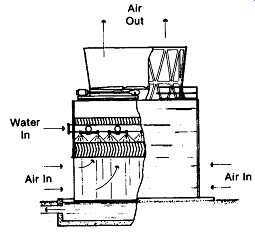
FIG. 5 Induced draft, counterflow tower (The Marley Cooling Tower Company)
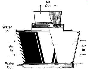
FIG. 6 Double-flow, crossflow tower. (The Marley Cooling Tower Company)
CHARACTERIZATION BY AIR FLOW
Cooling towers are also classified by the relative flow relationship of air and water within the tower, as follows: In counterflow towers ( FIG. 5), air moves vertically upward through the fill, counter to the downward fall of water. Because of the need for extended intake and discharge plenums, the use of high pressure spray systems, and the typically higher air pressure losses, some of the smaller counterflow towers are physically higher, require more pump head, and utilize more fan power than their crossflow counterparts. In larger counterflow towers, however, the use of low-pressure, gravity-related distribution systems, plus the availability of generous intake areas and plenum spaces for air management, is tending to equalize, or even reverse, this situation. The enclosed nature of a counterflow tower also restricts exposure of the water to direct sunlight, thereby retarding the growth of algae.
Crossflow towers ( FIG. 6) have a fill configuration through which the air flows horizontally, across the downward fall of water. Water to be cooled is delivered to hot water inlet basins located atop the fill areas and is distributed to the fill by gravity through metering orifices in the floor of those basins. This obviates the need for a pressure-spray distribution system and places the resultant gravity system in full view for ease of maintenance. By the proper utilization of flow-control valves, routine cleaning and maintenance of crossflow tower distribution systems can be accomplished sectionally, while the tower continues to operate.
Crossflow towers are also subclassified by the number of fill "banks" and air inlets that are served by each fan. The tower indicated in FIG. 6 is a double- flow tower because the fan is inducing air through two inlets and across two banks of fill. FIG. 7 depicts a single-flow tower having only one air inlet and one fill bank, the remaining three sides of the tower being cased. Single-flow towers are customarily used in locations where an unrestricted air path to the tower is available from only one direction. They are also useful in areas having a dependable prevailing wind direction, where consistent process temperatures are critical. The tower can be sited with the air inlet facing the prevailing wind, and any potential for recirculation is negated by the downwind side of the tower being a cased face.
Spray-filled towers have no heat transfer (fill) surface, depending only upon the water break-up afforded by the distribution system to promote maximum water-to- air contact. Removing the fill from the tower in FIG. 5 would also make it "spray-filled." The use of such towers is normally limited to those processes where higher water temperatures are permissible. They are also utilized in those situations where excessive contaminants or solids in the circulating water would jeopardize a normal heat transfer surface.
CHARACTERIZATION BY CONSTRUCTION
Field-erected towers are those on which the primary construction activity takes place at the site of ultimate use. All large towers, and many of the smaller towers, are prefabricated, piece-marked, and shipped to the site for final assembly. Labor and/or supervision for final assembly is usually provided by the cooling tower manufacturer.
Factory-assembled towers undergo virtually complete assembly at their point of manufacture, whereupon they are shipped to the site in as few sections as the mode of transportation will permit. A relatively small tower would ship essentially intact. Larger, multi-cell towers are assembled as "cells" or "modules" at the factory and are shipped with appropriate hardware for ultimate joining by the user. Factory-assembled towers are also known as "packaged" or "unitary" towers.
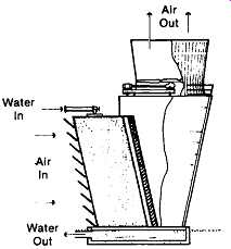
FIG. 7 Single-flow tower. (The Marley Cooling Tower Company)
CHARACTERIZATION BY SHAPE
Rectilinear towers ( FIG. ) are constructed in cellular fashion, increasing linearly to the length and number of cells necessary to accomplish a specified thermal performance.
Round Mechanical Draft (RMD) towers, as the name implies, are essentially round in plan configuration, with fans clustered as close as practicable around the centerpoint of the tower. Multifaceted towers, such as the octagonal mechanical draft (OMD) depicted in FIG. , also fall into the general classification of "round" towers. Such towers can handle enormous heat loads with considerably less site area impact than that required by multiple rectilinear towers. Additionally, they are significantly less affected by recirculation.
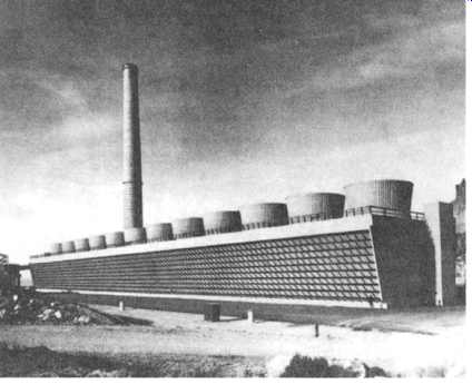
FIG. 8 Multicelled, field-erected, crossflow cooling tower with enclosed
stairway and extended fan deck to enclose piping and hot water basins.
(The Marley Cooling Tower Company)
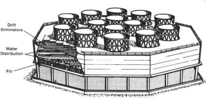
FIG. 9 Octagonal mechanical draft (OMD) counter-flow cooling tower. (The
Marley Cooling Tower Company)
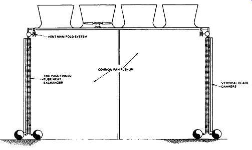
FIG. 10 Dry-type cooling tower, cross-sectional elevation. (The Marley Cooling
Tower Company)
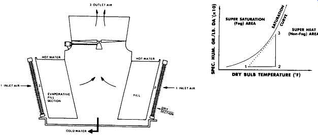
FIG. 11 Plume abatement tower and psychrometrics (coil before fill). (The
Marley Cooling Tower Company)
CHARACTERIZATION BY METHOD OF HEAT TRANSFER
All of the cooling towers heretofore described are evaporative-type towers, in that they derive their primary cooling effect from the evaporation that takes place when air and water are brought into direct contact. At the other end of the spectrum is the dry tower ( FIG. ), where, by full utilization of dry surface coil sections, no direct contact (and no evaporation) occurs between air and water. Hence the water is cooled totally by sensible heat transfer.
In between these extremes are the plume abatement and water conservation ( FIG. 12) towers, wherein progressively greater portions of dry surface coil sections are introduced into the overall heat transfer system to alleviate specific problems, or to accomplish specific requirements.
MECHANICAL COMPONENT REVIEW
Cooling tower mechanical equipment is required to operate within a highly corrosive moisture-laden atmosphere that is unique to the cooling tower industry, and the historical failure rate of commercially available components caused reputable tower manufacturers to undertake their own production of specific components some years ago. Currently, the low failure rate of manufacturer-produced components reinforces that decision. Purchasers also benefit from the advantage of single-source responsibility for warranty and replacement parts.
Exclusive of motors, the mechanical components basic to the operation of the cooling tower are fans, speed reducers, drive shafts, and water flow control valves.
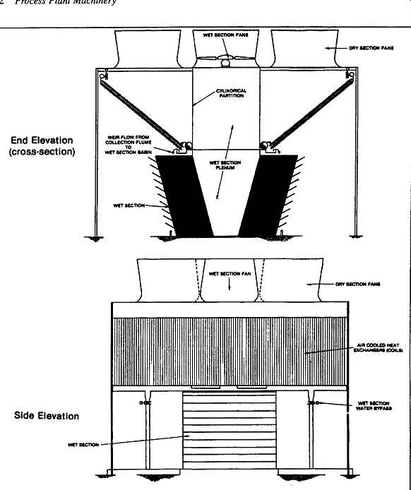
FIG. 12 Water conservation cooling tower. (The Marley Cooling Tower Company) End Elevation (cross-section); Side Elevation
Fans
Cooling tower fans must move large volumes of air efficiently and with minimum vibration. The materials of manufacture must not only be compatible with their design, but must also be capable of withstanding the corrosive effects of the environment in which the fans are required to operate. Their importance to the ability of mechanical draft cooling towers to perform is reflected in the fact that fans of improved efficiency and reliability are the object of continuous development.
Propeller Fans
Propeller-type fans predominate in the cooling tower industry because of their ability to move vast quantities of air at the relatively low static pressures encountered. They are comparatively inexpensive, may be used on any size tower, and can develop high overall efficiencies when "system designed" to complement a specific tower structure-fill-fan cylinder configuration. Most-utilized diameters range from 24 inches to 10 meters ( FIG. 13), operating at horsepowers from 1/4 to 250+. Although the use of larger fans, at higher power input, is not without precedence, their application naturally tends to be limited by the number of projects of sufficient size to warrant their consideration. Fans 48 inches and larger in diameter are equipped with adjustable pitch blades, enabling the fans to be applied over a wide range of operating horsepowers. Thus the fan can be adjusted to deliver the precise required amount of air at the least power consumption.
The rotational speed at which a propeller fan is applied typically varies in inverse proportion to its diameter. The smaller fans turn at relatively high speeds, whereas the larger ones turn somewhat slower. This speed-diameter relationship, however, is by no means a constant one. If it were, the blade tip speeds of all cooling tower fans would be equal. The applied rotational speed of propeller fans usually depends on best ultimate efficiency, and some diameters operate routinely at tip speeds approaching 14,000 feet per minute. However, since higher tip speeds are associated with higher sound levels, it’s sometimes necessary to select fans turning at slower speeds to satisfy a critical requirement.
The increased emphasis on reducing cooling tower operating costs has resulted in the use of larger fans to move greater volumes of air more efficiently. Much research has also gone into the development of more efficient blade, hub, and fan cylinder designs. The new generations of fans are light in weight to reduce parasitic energy losses, and have fewer, but wider, blades to reduce aerodynamic drag. Moreover, the characteristics of air flow through the tower, from inlet to discharge, are analyzed and appropriate adjustments to the structure are made to minimize obstructions; fill and distribution systems are designed and arranged to promote maximum uniformity of air and water flow; and drift eliminators are arranged to direct the final pass of air toward the fan. This is recognized as the "systems" approach to fan design, without which the best possible efficiency cannot be obtained.
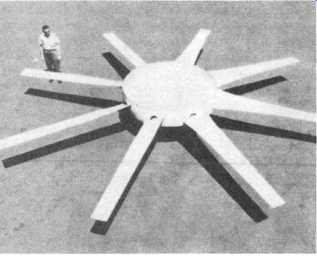
FIG. 13 Typical large-diameter fan utilized on cooling towers. (The Marley
Cooling Tower Company)
The intent of good propeller fan design is to achieve air velocities across the effective area of the fan, from hub to blade tips, that are as uniform as possible. The most effective way to accomplish this is with tapered and twisted blades having an airfoil cross section. Historically, cast aluminum alloys have been the classic materials used for production of this blade type. Cast aluminum blades continue to be utilized because of their relatively low cost, good internal vibration damping characteristics, and resistance to corrosion in most cooling tower environments.
Currently, lighter blades of exceptional corrosion resistance are made of fiberglass-reinforced plastic, cast in precision molds. These blades may be solid, formed around a permanent core, or formed hollow by the use of a temporary core.
In all cases, they have proved to be both efficient and durable as long as the design avoided aerodynamically induced vibration resonance.
Fan hubs must be of a material that is structurally compatible with blade weight and loading, and must have good corrosion resistance. Galvanized steel weldments, gray and ductile iron castings, and wrought or cast aluminum are in general use as hub materials. Where hub and blades are of dissimilar metals, they must be insulated from each other to prevent electrolytic corrosion.
Smaller diameter fans are customarily of galvanized sheet metal construction with fixed-pitch nonadjustable blades. These fans are matched to differing air flow requirements by changing the design speed.
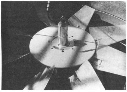
FIG. 14 Automatic, variable-pitch fan used to adjust air flow and fan horsepower,
(The Marley Cooling Tower Company)
Automatic Variable-Pitch Fans
These are propeller fans on which a pneumatically actuated hub controls the pitch of the blades in unison ( FIG. 14). Their ability to vary airflow through the tower in response to a changing load or ambient condition-coupled with the resultant energy savings and ice control - make them an optional feature much in demand.
Centrifugal Fans
These are usually of the double inlet type, used predominantly on cooling towers designed for indoor installations ( FIG. 15). Their capability to operate against relatively high static pressures makes them particularly suitable for that type of application. However, their inability to handle large volumes of air, and their characteristically high input horsepower requirement (approximately twice that of a propeller fan), limit their use of relatively small applications.
Three types of centrifugal fans are available: (1) forward curved blade fans, (2) radial blade fans, and (3)backward curved blade fans. The characteristics of the forward curved blade fan make it the most appropriate type of cooling tower service. By virtue of the direction and velocity of the air leaving the fan wheel, the fan can be equipped with a comparatively small size housing, which is desirable from a structural standpoint. Also, because the required velocity is generated at a comparatively low speed, forward curved blade fans tend to operate quieter than other centrifugal types.
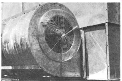
FIG. 15 Blower-type cooling tower fan. (The Marley Cooling Tower Company)
Centrifugal fans are usually of sheet metal construction, with the most popular protective coating being hot-dip galvanization. Damper mechanisms are also available to facilitate capacity control of the cooling tower.
Fan Laws
All propeller-type fans operate in accordance with common laws. For a given fan and cooling tower system, the following is true:
1. The capacity (cfm) varies directly as the speed (RPM) ratio, and directly as the pitch angle of the blades relative to the plane of rotation.
2. The static pressure (hs) varies as the square of the capacity ratio.
3. The fan horsepower varies as the cube of the capacity ratio.
4. At constant cfm, the fan horsepower and static pressure vary directly with the air density.
If, For example, the capacity (cfm) of a given fan were decreased by 50 percent (either by a reduction to half of design rpm, or by a reduction in blade pitch angle at constant speed), the capacity ratio would be 0.5. Concurrently, the static pressure would become 25 percent of before, and the fan horsepower would become 12.5 percent of before. These characteristics afford unique opportunities to combine cold water temperature control with significant energy savings.
Selected formulas, derived from these basic laws, may be utilized to determine the efficacy of any particular fan application: Symbols:
Q = Volume of air handled (cfm). Unit: cu ft per min.
A -- Net flow area. Unit: sq ft.
V -- Average air velocity at plane of measurement. Unit: ft per sec.
g = Acceleration due to gravity. Unit: 32.17 ft per sec per sec.
D ---- Density of water at gauge fluid temperature. Unit: lb per cu ft.
d = Air density at point of flow. Unit: lb per cu ft.
hs -- Static pressure drop through system. Unit: inches of water.
hv -- Velocity pressure at point of measurement. Unit: inches of water.
ht = Total pressure differential (= hs + hv). Unit: inches of water.
Vr = Fan cylinder velocity recovery capability. Unit: percent.
Thermal performance of a cooling tower depends on a specific mass flow rate of air through the fill (pounds of dry air per minute), whereas the fan does its job purely in terms of volume (cubic feet per minute). Since the specific volume of air (cubic feet per pound) increases with temperature, it can be seen that a larger volume of air leaves the tower than enters it. The actual cfm handled by the fan is the product of mass flow rate times the specific volume of dry air corresponding to the temperature at which the air leaves the tower. This volumetric flow rate is the "Q" used in the following formulas, and it must be sufficient to produce the correct mass flow rate or the tower will be short of thermal capacity.
Utilizing appropriate cross-sectional flow areas, velocity through the fan and fan cylinder can be calculated as follows:
It must be understood that "A" will change with the plane at which velocity is being calculated. Downstream of the fan, "A" is the gross cross-sectional area of the fan cylinder. At the fan, "A" is the area of the fan less the area of the hub or hub cover.
Velocity pressure is calculated as follows...
If V represents the velocity through the fan, then hv represents the velocity pressure for the fan itself (hvf). Moreover, if the fan is operating within a non-flared-discharge fan cylinder, this effectively represents the total velocity pressure because of no recovery having taken place.
However, if the fan is operating within a flared, velocity-recovery-type fan cylinder ( FIG. 16), hv must be recalculated for the fan cylinder exit (hve), at the appropriate velocity, and applied in the following formula to determine total velocity pressure:
hv = hvf - [(hvf - hve) x Vr]
Although the value of V r will vary with design expertise and is empirically established, a value of 0.75 (75 percent recovery) is normally assigned for purposes of anticipating fan performance within a reasonably well-designed velocity-recovery cylinder.
The power output of a fan is expressed in terms of air horsepower (ahp) and represents work done by the fan:
QxhtxD ahp = 33,000 x 12
Static air horsepower is obtained by substituting static pressure (hs) for total pressure (ht) in the formula.
A great deal of research and development goes into the improvement of fan efficiencies, and those manufacturers that have taken a systems approach to this research and development effort have achieved results that, although incrementally small, are highly significant in the light of current energy costs. Static efficiencies and overall mechanical (total) efficiencies are considered in the selection of a particular fan in a specific situation, with the choice usually going to the fan that delivers the required volume of air at the least input horsepower:
Static Efficiency - static ahp input hp ahp
Total Efficiency = . mput hp
It must be understood that input hp is measured at the fan shaft and does not include the drive-train losses reflected in actual motor brake horsepower (bhp). Input hp will normally average approximately 95 percent of motor bhp on larger fan applications.
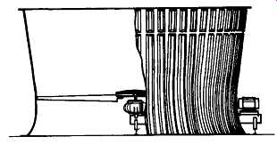
FIG. 16 Cutaway view of a velocity-recovery-type fan cylinder. (The Marley
Cooling Tower Company)
Speed Reducers
The optimum speed of a cooling tower fan seldom coincides with the most efficient speed of the driver (motor). This dictates that a speed reduction, power transmission unit of some sort be situated between the motor and the fan. In addition to reducing the speed of the motor to the proper fan speed (at the least possible loss of available power), the power transmission unit must also provide primary support for the fan, exhibit long-term resistance to wear and corrosion, and contribute as little as possible to the overall noise level.
Speed reduction in cooling towers is accomplished either by differential gears of positive engagement or by differential pulleys (sheaves) connected through V-belts. Typically, gear reduction units are applied through a wide range of horsepower ratings, from the very large down to as little as 5 hp. V-belt drives, on the other hand, are usually applied at ratings of 50 hp or less.
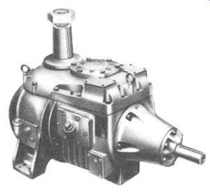
FIG. 17 Gear speed reducer used for applied horsepowers above 75 HP. (The
Marley Cooling Tower Company)
Gear Reduction Units
Gear speed reducers are available in a variety of designs and reduction ratios to accommodate the fan speeds and horsepowers encountered in cooling towers ( FIG. 17). Because of their ability to transmit power at minimal loss, spiral bevel and helical gear sets are most widely utilized, although worm gears are also used in some designs. Depending on the reduction ratio required and the input hp, a gear speed reducer may use a single type gear or a combination of types to achieve "staged" reduction. Generally, two-stage reduction units are utilized for the large, slower-turning fans requiting input horsepowers exceeding 75 bhp.
The service life of a speed reducer or speed increaser is directly related to the surface durability of the gears, as well as the type of service imposed (i.e., intermittent versus continuous duty). The American Gear Manufacturers Association (AGMA) has established criteria for the rating of geared speed reducers, which are subscribed to by most reliable designers. AGMA Standard 420 defines these criteria and offers a list of suggested service factors. The gear speed reducer manufacturer should have established service factors for an array of ratios, horsepowers, and types of service, commensurate with good engineering practice. The Cooling Tower Institute (CTI) Standard 111 offers suggested service factors specifically for cooling tower applications.
Long, trouble-free life is also dependent on the quality of bearings used. Bearings are normally selected for a calculated life compatible with the expected type of service. Bearings for industrial cooling tower gear speed reducers (considered as continuous duty) should be selected on the basis of a 100,000-hour L-10 life.
L-10 life is defined as the life expectancy in hours during which 90 percent or more of a given group of bearings under specific loading condition will still be in service. Intermittent duty applications provide satisfactory life with a lower L-10 rating. An L-10 life of 35,000 hours is satisfactory for an 8- to 10-hour per day application. It’s equivalent, in terms of years of service, to a 100,000-hour L-10 life for continuous duty.
Lubrication aspects of a gear speed reducer, of course, are as important to longevity and reliability as are the components that compose the gear speed reducer.
The lubrication system should be of a simple, noncomplex design, capable of lubricating equally well in both forward and reserve operation. Remote oil level indicators and convenient location of fill and drain lines simplify and encourage preventive maintenance. Lubricants and lubricating procedures recommended by the manufacturer should be adhered to closely. Synthetic lubricants may greatly increase both gear life and lubricant drainage intervals.
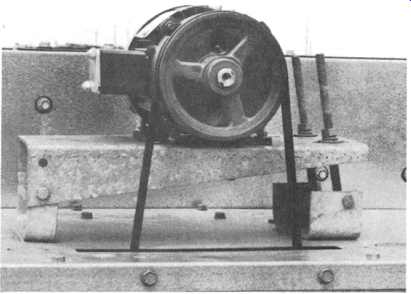
FIG. 18 Adjustable motor mount for a V-belt driven fan (belt guard removed).
(The Marley Cooling Tower Company)
V-Belt Drives
These are an accepted standard for the smaller factory-assembled cooling towers, although most of the larger unitary towers are equipped with gear speed reducers.
Correctly designed and installed, and well maintained, V-belt drives can provide very dependable service. The drive consists of the motor and fan sheaves, the bearing housing assembly supporting the fan, and the V-belts.
V-belts (as opposed to cog belts) are used most commonly for cooling tower service. A variety of V-belt designs is available, offering a wide assortment of features. Most of these designs are suitable for cooling tower use. In many cases, more than one belt is required to transmit power from the motor to the fan. Multiple belts must be supplied either as matched sets, measured and packaged together at the factory, or as a banded belt having more than one V-section on a common backing.
Various types of bearings and bearing housing assemblies are utilized in conjunction with V-belt drives. Generally, sleeve bearings are used on smaller units and ball or roller bearings on the larger units, with oil being the most common lubricant. In all cases, water slinger seals are recommended to prevent moisture from entering the beating, and oil mist is often used as a purge medium to prevent moisture condensation in bearing housings.
Belts wear and stretch, and belt tension must be periodically adjusted. Means for such adjustment should be incorporated as part of the motor mount assembly.
Stability and strength of the mounting assembly is of prime importance in order to maintain proper alignment between driver and driven sheaves ( FIG. 18). Misalignment is one of the most common causes of excessive belt and sheave wear.
Manually adjustable pitch sheaves are occasionally provided to allow a change in fan speed. These are of advantage on indoor towers, where the ability to adjust fan speed can sometimes compensate for unforeseen static pressure.
FIG. 19 Driveshafi in a relatively small fan drive application. (The Marley
Cooling Tower Company)
Drive Shafts
The drive shaft transmits power from the output shaft of the motor to the input shaft of the gear speed reducer. Because the drive shaft operates within the tower, it must be highly corrosion resistant. Turning at full motor speed, it must be well balanced--and capable of being rebalanced. Transmitting full motor power over significant distances, it must accept tremendous torque without deformation.
Subjected to long-term cyclical operation and occasional human error, it must be capable of accepting some degree of misalignment.
Drive shafts are described as "floating" shafts, equipped with flexible couplings at both ends. Where only normal corrosion is anticipated and cost is of primary consideration, shafts are fabricated of carbon steel, hot-dip galvanized after fabrication ( FIG. 19). Shafts for larger industrial towers, and those that will be operating in atmospheres more conducive to corrosion, are usually fabricated of tubular stainless steel ( FIG. 20) or epoxy-coated wound carbon filament. The yokes and flanges that connect to the motor and gear speed reducer shafts are of cast or welded construction, in a variety of materials compatible with that utilized for the shaft.
Flexible couplings transmit the load between the driveshaft and the motor or gear speed reducer, and compensate for minor misalignment. A suitable material for use in the saturated effluent air stream of a cooling tower is neoprene, either in solid grommet form ( FIG. 21) or as neoprene-impregnated fabric ( FIG. 22), designed to require no lubrication and relatively little maintenance. Excellent service records have been established by the neoprene flexible couplings, both as bonded bushings and as impregnated fabric disc assemblies. These couplings are virtually impervious to corrosion and provide excellent flexing characteristics.
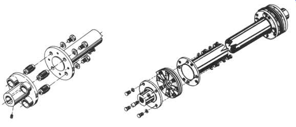
FIG. 21, 22
It’s very important that drive shafts be properly balanced. Imbalance not only causes tower vibration, but it also induces higher loads and excessive wear on the mechanical equipment coupled to the shaft. Most cooling tower drive shafts operate at speeds approaching 1800 RPM. At these speeds, it’s necessary that the shafts be dynamically balanced to reduce vibrational forces to a minimum.
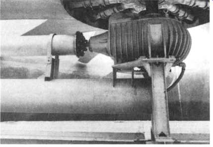
FIG. 20 Close-up of a larger driveshaft showing guard. (The Marley Cooling
Tower Company)
Safety Considerations
Fan cylinders less than six feet high must be equipped with suitable fan guards for the protection of operating personnel. Drive shafts must operate within retaining guards ( FIG. 20) to prevent the drive shaft from encountering the fan if the coupling should fail. The motor shaft and outboard drive shaft coupling should either be within the confines of the fan cylinder or enclosed within a suitable guard.