AMAZON multi-meters discounts AMAZON oscilloscope discounts
An amazing number of process plant applications require vacuum systems for continuous or intermittent services. Central vacuum systems are often found in power stations and in industrial and marine installations for the purpose of priming large centrifugal pumps; similar systems provide vacuum for surgical and clinical purposes in hospitals, dentist's offices, and laboratories.
In sterilization processes, vacuum pumps remove air to permit rapid penetration of steam and/or gas into articles requiring sterilization. Food processing plants utilize vacuum systems for anything from poultry evisceration to final packaging in bags, windows, or blister packs for enhanced appearance and marketability. Vacuum filtration is used for sewage, chemicals, foods, and many mined or fibrous products.
Many condensing processes utilize vacuum pumps to evacuate condensers and to remove air leakage and noncondensibles. Smaller installations use liquid ring vacuum pumps in a dual role, removing condensates as well as noncondensibles, sometimes utilizing the cooled condensate as a service liquid. Vacuum pumps are also used in impregnation and metallurgical treatment processes where air and gas have to be removed prior to impregnation with appropriate chemical fluids; or prior to the application of diffusion coatings, or in advanced ion and plasma-type surfacing techniques.
Vacuum pumps are used for drying, distillation, and evaporation. Lower boiling temperatures attained under vacuum preserve nutrients and improve taste, quality, and shelf life of products such as candies, jams, pharmaceuticals, and many mild products. De-aeration is needed for products such as meat pastes, sauces, soups, cellulose, latex, bricks, tiles, sewer pipes, and pottery clay. Also, vacuum conveyance of dangerous, viscous, contaminated, powdery, flaky, bulky, or simply hard-to-handle materials or products is used. The author remembers the ease and utter simplicity with which laminated plastic toothpaste tubes are transferred in partially evacuated, transparent plastic pipes from the forming machine at one end of the plant to the filling equipment at the other end of the building.
With a profusion of processes and applications thus benefiting from vacuum pumps, it’s not surprising that many different types and styles, sizes and models, configurations and variations of vacuum producing machinery are available to the user. The familiar steam, gas, and fluid jet injectors/eductors must be acknowledged as prime vacuum producers; however, we will only mention them in passing because they lack moving parts and thus don’t fit our definition of "machinery." Vacuum pumps are often classified in two broad categories: dry type and liquid type. Dry types include lobe, rotary piston, sliding vane, and even diaphragm pumps.
Liquid vacuum pumps include liquid jet and liquid ring pumps. FIGs 1 and 2 show the operating ranges for many of these pumps. It should be noted that there is considerable overlap among ranges.
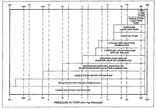
FIG. 1 Typical pressure ranges for various vacuum pumping devices. (Stokes
Division of Pennwalt Corporation, Philadelphia, PA.)
The most important vacuum producers and their respective operating modes and features are of interest to us in the order listed in FIG. 1.
SINGLE-STAGE LIQUID RING PUMPS
FIG. 3 depicts the operating principle of a liquid ring pump. Its circular pump body (A) contains a rotor that consists of a shaft and impeller (B). Shaft and impeller center-lines are positioned parallel, but eccentrically offset relative to the centerline of the pump body. The amount of eccentricity is related to the depth of the liquid ring (C). The liquid ring is formed by introducing service liquid, normally water, via the pump suction casing (L) and through the channel (D) positioned in the suction port plate (E). The centrifugal action of the rotating impeller forces the liquid toward the periphery of the pump body. By controlling the amount of service liquid within the pump body where the impeller blades are completely immersed to their root at one extreme (F) and all but their tips exposed at the other extreme (G), optimum pumping performance will be attained.
When this pumping action is achieved, the vapor to be handled is induced through the suction port (H) when the depth of impeller blade immersion is being decreased. Then as the immersion increases, the vapor is compressed and discharged through the discharge port (J) in the intermediate port plate (K). As there is no metal- to-metal contact between the impeller and the pump body and intermediate plates, the need for lubrication is eliminated and wear is reduced to a minimum.
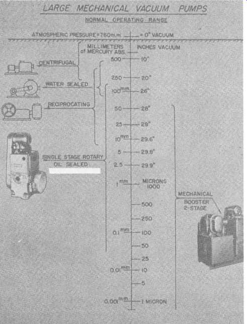
FIG. 2 Operating range of large mechanical vacuum pumps. (Stokes Division
of Pennwalt Corporation, Philadelphia, PA.)
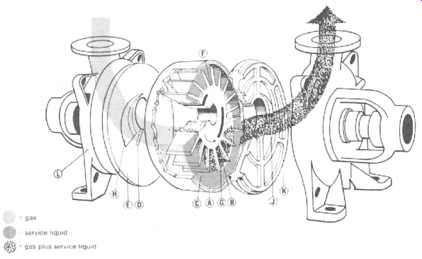
FIG. 3 Operating principle of liquid vacuum pumps. (SIHI Pumps, Inc., Grand
Island, NY. )
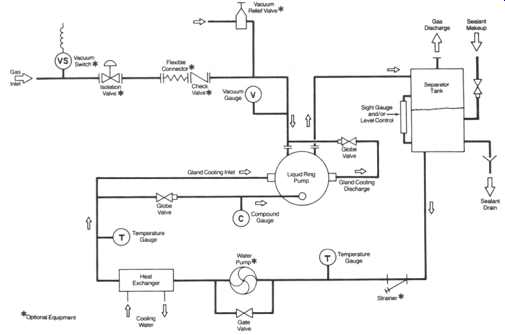 FIG. 4 Liquid ring vacuum pumping system with full sealant recovery. (Kinney
Vacuum Company, Boston, MA.)
FIG. 4 Liquid ring vacuum pumping system with full sealant recovery. (Kinney
Vacuum Company, Boston, MA.)
During the compression cycle heat is being imparted to the liquid ring. In order to maintain a temperature below the vapor point, cooling must be applied.
This cooling is achieved by continuously adding a cool supply of service liquid to the liquid ring. The amount of coolant added is equal to that discharged through the discharge port (J) together with the compressed vapor. The mixture of vapor and liquid is then passed to subsequent stages and eventually through the pump discharge for separation.
An entire vacuum pumping system is shown in FIG. 4. This so-called full sealant recovery system is used to conserve sealant and/or where suitable or compatible sealant is not available from an outside source. Periodic sealant makeup and/or purge may be required. Full recirculation of sealant is provided from the discharge separator tank. Cooling is provided by running recirculated sealant through a heat exchanger. Separate cooling liquid or gas is required.
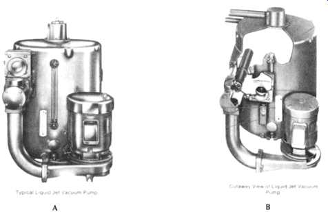
FIG. 5 (A) Typical liquid jet vacuum pump. (B) Cutaway view of liquid vacuum
pump. (Kinney Vacuum Company, Boston, MA.)
LIQUID JET VACUUM PUMPS
A typical liquid jet pump is illustrated in FIG. 5. A centrifugal pump circulates water (the usual hurling liquid) through the multi-jet nozzle and venturi and returns it to the separation chamber. The water, forced at high velocity across the gap between the nozzle and venturi, entrains the air and gases in multiple jet streams, creating a smooth, steady vacuum in the air suction line and vacuum system. This mixture is discharged through the venturi tangentially into the separation chamber, causing the water in the separation chamber to rotate, which results in a centrifugal action that forces the water to the periphery of the chamber, while the air is separated and discharged. When the hurling liquid is water, it’s cooled by a continuous flow of cooling water into the separation chamber. Where process requirements allow and economy is an important factor, automatic controls and other cooling methods are often utilized.
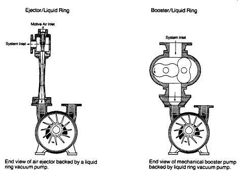
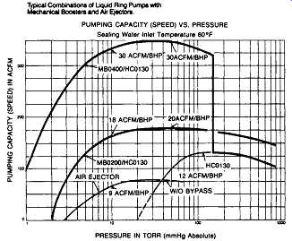
FIG. 6 Liquid ring pumps with air ejector and mechanical booster. (Kinney
Vacuum Company, Boston, MA.) End view of air ejector backed by a liquid ring
vacuum pump.
End view of mechanical booster pump backed by liquid ring vacuum pump.
AIR EJECTOR AND/OR BOOSTER LIQUID RING PUMPS
Air ejectors or mechanical booster pumps are often used upstream of liquid ring pumps for applications requiring higher pumping speeds and lower pressures. These systems are particularly suited for processes where freedom from oil in the pumping system is required, such as oxygen handling, or where pump oil contamination makes the use of oil-sealed pumps impractical or expensive.
FIG. 6 shows how the addition of air ejectors or mechanical booster pumps can extend the range of liquid ring vacuum pumps.
MULTISTAGE COMBINATION UNITS
Multistage vacuum units consist of one or two rotary blowers, the necessary intermediate gas coolers, possibly a gas ejector, and a liquid ring vacuum pump.
All this equipment is typically mounted on a single-base frame.
The entire system consists of the rotary blower(s), gas ejector, and liquid ring vacuum pump are connected in series, whereby the extracted gases flow first through the blower, then the gas ejector, and finally the liquid ring vacuum pump. The latter can be operated with fresh water or with a closed ring-liquid circuit. This is always indicated when the evacuated gases and vapors are not allowed to be routed to the atmosphere or discharged into the sewage system for environmental protection reasons, or if the vapors contain valuable raw materials that have to be recovered by means of condensation. In such cases, the self-priming liquid ring vacuum pump draws the liquid out of the tank. The gas and liquid are then separated and cooled in the heat exchanger. The liquid returns to the tank and the gas passes through the exhaust gas cooler, where the condensibles are recovered before leaving the system.
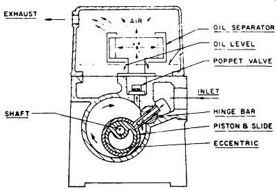
FIG. 7 Rotary piston oil-sealed vacuum pump. (Stokes Division of Pennwalt
Corporation, Philadelphia, PA.)
ROTARY OIL-SEALED VACUUM PUMPS
Of the variety of mechanical vacuum pumps described earlier and illustrated in FIG. 2, the unit most commonly used for high-vacuum work is the rotary piston, oil-sealed, single-stage mechanical vacuum pump ( FIG. 7). This pump type, sometimes called a cam and piston pump, is typically capable of producing ultimate pressures below 10 microns. Its normal operating range is between 0.05 Torr and 100 Torr, and typical evacuation rates range from 10 to 1000 cubic centimeters per minute.
The rotary oil-sealed pump employs an eccentrically mounted piston-slide assembly, rotating at speeds of 400 RPM and higher, depending on pump size.
The vacuum "seal" is maintained by a "wedge" of oil ahead of the piston. The oil wedge prevents blow-by of gases and provides lubrication.
In operation, the gas to be evacuated enters the rotary oil-sealed vacuum pump freely through the intake port of the piston-slide. As the oil-sealed piston revolves, it closes the inlet port from the vacuum system and traps ahead of it all air or gas that has entered. With each revolution of the pump, the gas is compressed and discharged through the valve ports to the atmosphere or to a collecting system.