AMAZON multi-meters discounts AMAZON oscilloscope discounts
Positive displacement pumps can be divided into two major categories: reciprocating and rotating. Reciprocating pumps include steam pumps and power pumps, as defined later. Many reciprocating pumps use a flexible membrane or diaphragm and are collectively called diaphragm pumps. Every one of the various types comes in a wide range of sizes, or with modifications, additions, and perhaps auxiliary support equipment.
The same is true for the many different types of rotating positive displacement pumps. They include gear pumps, screw pumps, and peristaltic pumps, to name just a few.

above: A 50 l/min., KPM 80 series, positive displacement pump.
Each pump category, reciprocating and rotating, can be found in virtually every process plant we would typically encounter in the industrialized world. Not surprising, each has a definite application range, and the vast majority of these application ranges overlap each other.
RECIPROCATING POSITIVE DISPLACEMENT PUMPS
Reciprocating positive displacement pumps incorporate a plunger or piston that displaces, or feeds forward, a given volume of fluid per stroke. The basic principle of a reciprocating positive displacement pump is that moving a solid component into the space occupied by a liquid will result in an equal volume of liquid being moved out of that space.
To better understand reciprocating positive displacement pumps and their subgroup metering pumps, we must investigate their place within the universe of pumps. The pump universe could be organized in a variety of ways, such as by design, materials of construction, or the liquids pumped. For the purpose of this discussion, it’s appropriate to organize the pump universe by classifying pumps based on the method by which the pump imparts energy to the liquid being pumped.
This results in two basic classes of pumps" dynamic and displacement. Dynamic pumps encompass those shown on the left-hand side of FIG. 1, and these impart energy to the liquid in a steady fashion. Displacement pumps encompass the remaining pumps in FIG. 1, and these impart energy to the liquid in a pulsating fashion.
The usual basic characteristics of the dynamic and displacement pumps are shown in TBL. 1. By examining this table, it’s possible to identify the class of pump required for the job from its characteristics.
This segment of our text is primarily concerned with the world of metering pumps, which is within the positive displacement, reciprocating class of pumps.
Reciprocating pumps can be divided into two general categories: steam pumps and power pumps.
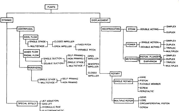
FIG. 1 Classification of the pump universe. (Pump Handbook, edited by Igor
J. Karassik, William J. Krutzsch, Warrent H. Fraser, and Joseph P. Messina.
McGraw Hill, New York, NY, 1985)
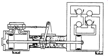
FIG. 2 Steam pump. (Hydraulic Institute Standards, 13th Edition, Cleveland,
OH, 1975)
Steam Pumps
Steam pumps consist of a liquid and steam cylinder joined together by a spacer cradle ( FIG. 2). These pumps may be steam or air driven. The liquid end consists of liquid inlet and outlet ports, valves, and a piston or plunger. The steam or air end consists of valve mechanisms and pistons. Normally, steam pumps are not designed to allow adjustment of the output flow while operating. This precludes their use as a metering pump in a system requiring frequent adjustment of flow rate.
Power Pumps
Power pumps consist of a liquid end and a power end ( FIG. 3). These pumps are generally driven by electric motors, air- or gasoline-driven motors, or any device imparting a rotary or reciprocating motion to the pump. The liquid end consists of inlet and outlet ports, valves, and pistons or plungers. The power end consists of the frame, crankshaft, bearings, connecting rods, crossheads, and, sometimes, reduction gears.
======
TBL. 1 Basic Characteristics of Modem Pumps
Dynamic Centrifugal Rotary Displacement Steam Power Reciprocating Metering Piston or Plunger Diaphragm
======
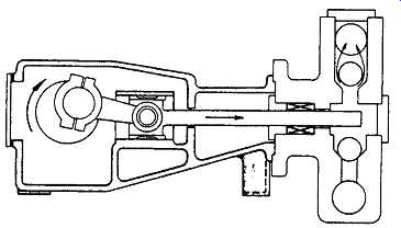
FIG. 3 Power pump. (Hydraulic Institute Standards, 13th Edition, Cleveland,
OH, 1975)
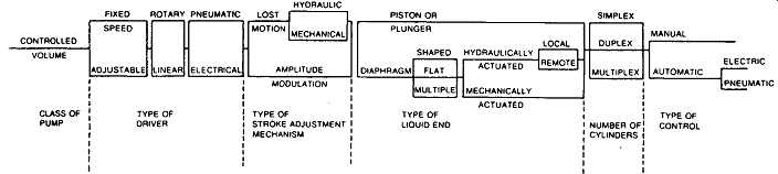
FIG. 4 Classes of metering pumps. (Hydraulic Institute Standards, 13th Edition,
Cleveland, OH, 1975)
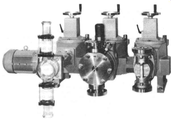
FIG. 5 Three metering pumps driven from a common input shaft. (LEWA, Leonberg,
Germany)
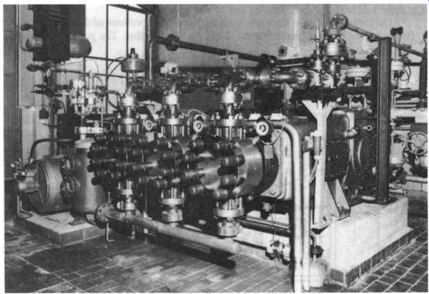
FIG. 6 Large diaphragm-type pumps in a chemical plant. (LEWA, Leonberg,
Germany)
Falling within this category of pumps are those designed with adjustment of output flow as well as those lacking this feature. Because a metering pump requires the adjustment of output flow in a typical process system, we will limit the remainder of this section to those power pumps with adjustable output flow.
Metering Pumps
FIG. 4 subdivides the metering pump class of power pumps into various types.
These types delineate the methods and geometries commercially used to produce a metering pump.
Metering pumps should be considered, first, as precision instruments used to feed accurately a predetermined volume of liquid into a process or system. Their secondary function is to pump, or move, a liquid from one point to another. They contain special adaptations of the conventional positive displacement reciprocating class of pumps, which are designed primarily to transfer liquid at an accurately controlled rate. They differ in that the pumping rates of metering pumps can be varied by changing the effective stroke length and, perhaps, by changing the speed.
More importantly, the flow rates of metering pumps can be accurately predetermined, with repeatable flows maintained consistently to within 4-1 percent.
Metering pumps come in an extremely large variety of sizes and configurations.
FIGs 5 and 6 give a glimpse of this variety.
Ideally, a metering pump should be capable of handling a wide range of liquids, including those that are toxic, corrosive, dangerous, volatile, and abrasive, as well as those containing concentrations of suspended solids (slurries). In addition, a metering pump should be able to generate sufficiently high discharge pressures to permit injection of liquids into processes. To accomplish this wide range of requirements, many options in design must be available, including the following:
++Size or capacity
++Method of control
++Materials composing the liquid-handling end
++Valve styles
++Primary drive requirements
++Environmental conditions
Metering pumps fall into four basic types, defined by the method used to seal the liquid end of the pump from the power end, thus preventing leakage and pumping inaccuracies:
++Piston, packed seal
++Plunger, gland packed seal
++Mechanical diaphragm seal
++Hydraulic diaphragm seal
The power end of the metering pump is common to all four types, with various designs used to generate the reciprocating movement required to power the liquid end.
Most metering pump designs employ an electric motor as a power source. The motor speed can be reduced to pump design speed by the use of internal motor gears or through gearing built into the pump power end. This rotary power is converted to a linear motion through a crank mechanism producing power in a straight-line reciprocating motion. Depending on the type of adjustable output flow mechanism used, the power can be utilized on both the forward thrust of the crank and the back thrust of the crank. Other capacity controls, however, only take advantage of the power in one direction.
There are also metering pumps with electromagnetic and pneumatic power ends creating linear, reciprocating motion using electromagnets and pneumatic pistons, respectively. Although they use conventional liquid end designs, they use highly specialized components to produce this linear reciprocating action. However, the over-whelming majority of metering pumps use some form of crank motion, which is then linked to a crosshead device for positive alignment of the piston or plunger to its cylinder ( FIGs 7 and 8). Packed Piston Pump. The packed piston metering pump uses a power end as just described. The piston is driven by either a crank, a connecting rod, or a crosshead driven by the crank. The piston is the measuring component of the metering pump, designed to displace a measured volume of liquid with a high degree of accuracy as it reciprocates within the pump. The packing used moves back and forth with the piston to effect a dynamic seal with the inside diameter of the cylinder and a static seal with the outside diameter of the piston.
The forward travel of the piston reduces the internal volume of the liquid chamber, displacing the metered liquid out the discharge check valve. The pressure required to move the liquid through the discharge check valve is also applied to the suction check valve, forcing it into a closed position, ensuring correct flow direction.
===
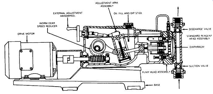
FIG. 7 Adjustable stroke reciprocating power mechanism. (Pulsafeeder, Rochester,
NY). ADJUSTMENT ARM ASSEMBLY EXTERNAL ADJUSTMENT. FILL AND DiP STICK
HANDWHEEL WORM GEAR SPEED REDUCER DRIVE MOTOR DISCHARGE VALVE STANDARD REAGENT
HFAD ASSEMBLY DIAPHRAGM SUCTION VALVE PUMP HEAD ASSEMB.
===
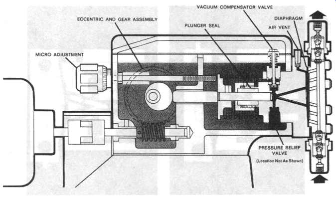
FIG. 8 Cam-driven reciprocating power mechanism. (Pulsafeeder, Rochester,
NY)
FIG. 9 Packed piston pump. (Hydraulic Institute Standards, 13th Edition, Cleveland, OH, 1975)
The reverse travel of the piston decreases the pressure within the liquid chamber by enlarging the internal volume of the chamber. This change of pressure results in a rapid closing of the discharge check valve caused by the external pressure acting on the valve and allows the suction check valve to open because of an external pressure under the check valve that can be either above or below atmospheric pressure. An added feature of the packed piston pump is its ability to be double acting, i.e., if so designed, to provide a discharge of fluid into a system on both the forward thrust of the piston and the back thrust of the piston. This feature provides up to twice the output capacity for the same horsepower input and minimizes the typical pulsing output flow common to reciprocating pumps.
The accuracy of the reciprocating metering pump is achieved by the previously described predetermined controlled piston travel of the pump, the control of the strokes per minute, and the precise opening and closing of the check valves. The inaccuracy, on the other hand, is caused by leakage past the piston packing and the check valves.
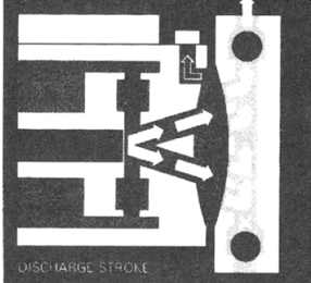
FIG. 10 Valve action during discharge stroke of diaphragm-type metering
pump. (Pulsafeeder, Rochester, NY)
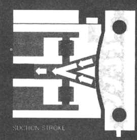
FIG. 11 Valve action during suction stroke of diaphragm-type metering pump.
(Pulsafeeder, Rochester, NY)
Packed Plunger Pump. The packed plunger pump is very similar to the packed piston pump except for the packing design and location. The packed plunger, unlike the packed piston, has the packing installed in a stationary gland in the inside diameter of the cylinder. As the plunger reciprocates within the pump, a dynamic seal is made between the outside diameter of the plunger and the inside diameter of the packing, and a static seal is made between the outside diameter of the packing and the inside diameter of the stuffing box ( FIG. 12). The choice between a packed piston pump or a packed plunger pump is dependent on many variables including fluid compatibility with the packing, speed of the piston or plunger, allowable leakage, and pressure requirements.
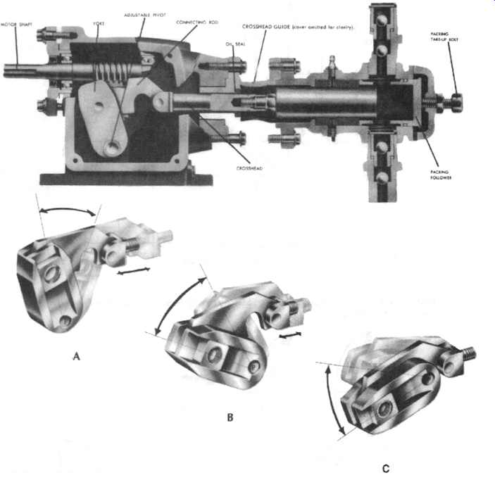
FIG. 12 Packed plunger metering pump. Stroke length is adjusted by changing
the position of the pivot P. (A) When the yoke is positioned at right angles
to crosshead motion, the eccentricity is all directed to the crosshead and
full stroke results. (B) For any intermediate position of the yoke, any interediate
stroke length results. (C) When the yoke is positioned parallel to crosshead
motion, the action of the crank is no longer directed to the crosshead, and
minimum stroke results. (Milton Roy Company, St. Petersburg, FL)
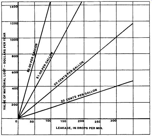
FIG. 13 Cost of leakage. (Metering Pump Handbook, Industrial Press, Inc.,
New York, NY, 1984)
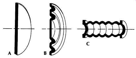
FIG. 14 Mechanical diaphragm styles. (A) Flat disk; (B) convoluted disk;
(C) bellows. (Pulsafeeder, Rochester, NY)
===
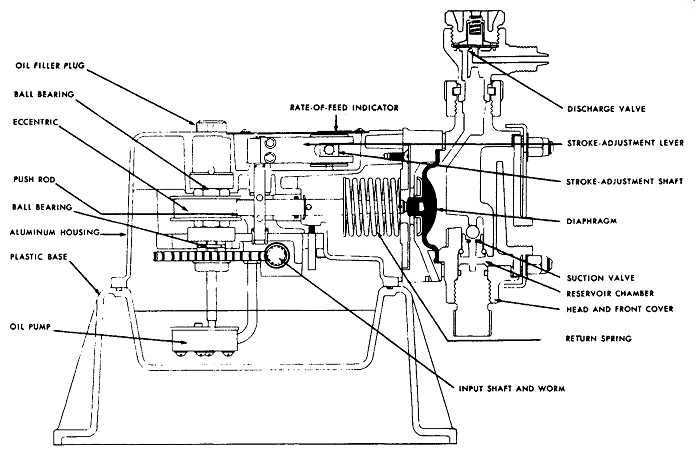
FIG. 15 Mechanical diaphragm pump. (Wallace and Tiernan, Belleville, NJ).
OIL FILLER PLUG BALL BEARING ECCENTRIC PUSH ROD BALL BEARING ALUMINUM PLASTIC
BASE OI L PUMP RATE.OF.FEED INDICATOR ; DISCHARGE VALVE STROKE.ADJUSTMENT
LEVER STROKE.ADJUSTMENT SHAFT DIAPHRAGM; RETURN SPRING INPUT SHAFT AND
WORM
===
Mechanical Diaphragm Pumps. Both the packed piston pump and the packed plunger pump allow some degree of leakage past their dynamic seals. In some cases, this is not an objectionable shortcoming; in other cases, it can be very objectionable and, in most instances, costly as well. For example, a leakage rate of only 25 drops per minute, metering a fluid costing $1.00 a gallon, can cost $200 per year in lost fluid ( FIG. 13). To be considered also is the cost of pressure flushing, drainage, contamination, maintenance, and loss of accuracy.
To overcome the leakage problem, a mechanically actuated diaphragm pump can be used. The power side of the pump and the capacity control are the same as were previously described for other types of reciprocating pumps. However, in place of a piston rod or plunger, the mechanical diaphragm pump uses a connecting rod fastened to the center of a diaphragm. The configuration of the diaphragm itself can take on many forms, but the most popular designs are those illustrated in FIG. 14 - the flat disk, the convoluted disk, and the bellows.
In the mechanical diaphragm pump, the principle of positive displacement output is similar to that of the piston plunger pump except that the diaphragm becomes the displacement measuring element, as it moves back and forth in the fluid chamber ( FIG. 15). Hydraulic Diaphragm Pump. The hydraulically balanced diaphragm pump is a hybrid design that provides the principal advantages of the other three pump types.
Like the other pumps, its power end and capacity are common. This, however, is where the similarity ends, since the piston or plunger does not come into contact with the pumped fluid, and the actuation of the diaphragm is by hydraulic power instead of mechanical power ( FIG. 7). The measuring piston or plunger reciprocates within a precisely sized cylinder at an established stroke length, displacing a volume of hydraulic liquid, not the product liquid. The hydraulic liquid is stable and has excellent lubricating qualities.
The piston uses the hydraulic oil to move the diaphragm forward and backward ( FIGs 10 and 11), causing a displacement that expels the product liquid through the discharge check valve and, on the suction stroke, takes in an equal amount through the suction check valve. The diaphragm isolates the liquid product being contained within the liquid chamber and check valves. These are the only parts that must be made of chemically compatible materials.
The only function of a diaphragm is to separate two liquids. The diaphragm normally does no work, carries no load, and pumps no liquid; rather, it serves as a moving barrier between liquids during periods of pressure imbalance. It’s simply a moving partition with pressure hydraulically balanced on both sides; on one side is the liquid product and on the other side is the hydraulic oil. At full deflection, the diaphragm undergoes total combined stresses well within the endurance limit of the diaphragm material. Contoured support plates are provided on either side of the diaphragm to ensure that stresses are kept within limits. When properly installed and working within the recommended temperature range and not affected by corrosion or abrasion, the diaphragm has an unlimited life.
As previously stated, the piston or plunger handles only hydraulic oil. Conventional seals are used on the piston or plunger, which does not require power flushing and complicated drain systems, as are found on conventional piston or plunger pumps handling corrosive or hazardous liquids.
Even the slightest leakage past the piston is replaced on the suction stroke through the automatic functioning of a compensation system, which draws in replacement oil from the oil reservoir ( FIG. 16). Any excess pressure within the hydraulic system or the liquid product chamber is relieved through the automatic action of a pressure relief valve. This valve blows off oil, under excess pressure ahead of the piston, back into the oil reservoir ( FIG. 17).
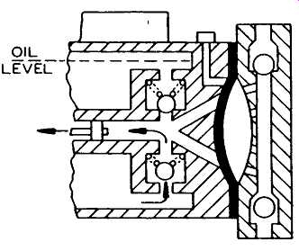
FIG. 16 Function of oil makeup valve. (Metering Pump Handbook, Industrial
Press, Inc., New York, NY, 1984)
The vacuum and pressure compensator systems actually perform three important functions that the other described types of metering pumps cannot do unless auxiliary equipment is added to their piping systems. As described previously, they compensate for any leakage occurring within the hydraulic system of the pump, ensuring a balanced diaphragm movement. In addition, they serve to protect the process system from over-pressure conditions produced by the pump. For instance, the positive displacement pump, because of its design, causes excess pressure within the system to the point of damaging the pump, bursting pipes, or damaging other downstream equipment should an operator mistakenly close a shut-off valve downstream from the pump. The hydraulic diaphragm pump will, however, relieve any pump-produced pressure beyond the set pressure of the pressure relief valve, thus avoiding the dangerous buildup of pressure. The compensation system also serves to protect the pump from a closed suction line or a partially clogged strainer in the suction line. Should this occur, the backward movement of the diaphragm is prevented and the vacuum relief system would automatically open to relieve the starved suction condition within the pump. In doing so, however, a surplus of hydraulic oil enters into the system between the diaphragm and piston. As the piston starts forward on its discharge stroke, the diaphragm is displaced forward and will come into contact with the contoured dish support plate in the process liquid chamber, because of the surplus oil drawn into the hydraulic chamber. At the moment of diaphragm contact with its support plate, an over-pressure condition starts to develop within the hydraulic system. The pressure relief valve now opens to relieve the surplus oil back into the hydraulic reservoir, preventing a dangerous buildup of pressure. The interaction of the two compensation systems continues stroke after stroke to activate a fluid clutch-type action to prevent overloading of the pump power end until the condition plugging the suction or discharge lines is found and corrected.
As in all properly designed hydraulic systems, an air-bleed system is required to purge air from the hydraulic system either automatically or manually.
Because the diaphragm is actuated hydraulically, this type of pump is highly adaptable. The product liquid chamber can be separated from the power end of the pump, using a pipe or tube to transfer the hydraulic power required. This feature is highly desirable when metering toxic, high- or low-temperature extremes. Additional diaphragms may also be added to accomplish various system requirements.
Summary. In summary, the principal features and limitations of each type of metering pump are listed on page 322.
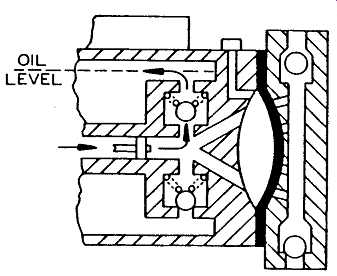
FIG. 17 Function of pressure relief valve. (Metering Pump Handbook, Industrial
Press, Inc., New York, NY, 1984)
=====
FEATURES | LIMITATIONS
Piston Pump
1. Low cost
2. Can be double acting
3. Capacities from a few cubic centimeters per hour to 1200 gallons per hour (gph) (4.5 x 10³ liters/hr)
4. Packing adjustment not required
5. Accuracies to 1 percent over 10:1 range
6. Can pump high-viscosity fluids
1. Packing leakage is unavoidable, a consideration with corrosive or dangerous chemicals
2. Unsuitable for abrasive slurries
3. Maintenance needed for piston packing
4. No built-in relief features
5. Dynamic packing subject to differential pressure
Packed Plunger Pump
1. Relatively low cost
2. Capacities from a few cubic centimeters per hour to over 20,000 gph (7.6 x 10⁴ liters/hr)
3. Accuracies to 1 percent over 15:1 range
4. Pressure capability to 50,000 psi (3.5 x 10⁵ kPa)
5. Least effect from changes in discharge pressure
6. Can pump high-viscosity liquids
1. Packing wear requires periodic adjustment
2. Packing leakage is unavoidable, a consideration with corrosive or dangerous chemicals
3. Unsuitable for abrasive slurries
4. Maintenance needed for packing and plunger wear
5. Pressure flushing or draining of packing gland required
6. No built-in relief
Mechanical Diaphragm Pump
1. Relatively low cost
2. Zero chemical leakage
3. Can pump abrasive slurries and chemicals
4. Packing adjustment not required
5. Can pump high-viscosity liquids
1. High maintenance due to high-stress loading of the diaphragm
2. Discharge pressure limitation of 200 psi (1.4 • 103 kPa)
3. Accuracy in the 5 percent range and as much as 10 percent zero shift with pressure change from minimum to maximum
4. Limited capacity range
5. Dynamic packing subject to differential pressures
6. No built-in safety features
Hydraulic Diaphragm Pump
1. Zero chemical leakage
2. High adaptability
3. Can pump wide range of liquids
4. Packing adjustment not required
5. Low maintenance
6. Pressures to 5000 psi (3.5 x 10⁴ kPa)
7. Accuracies 1 percent and capacities from a few cubic centimeters per hour to 1500 gph (5.7 x 10³ liters/hr)
8. Built-in safety features
1. Higher initial cost
2. Subject to a predictable zero shift of 5 percent to 10 percent per 1000 psig (6.9 x 10³ kPa)
3. Limited to moderate-viscosity fluids
=====
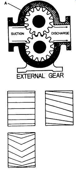
FIG. 18 External gear pump. (Dresser-Worthington, Harrison, NJ)
ROTATING POSITIVE DISPLACEMENT PUMPS
External and internal gear pumps are prevalent not only in the process industries but in general machinery and industrial equipment as well. The external gear pump ( FIG. 18) is probably the most widely used rotary pump. It consists of two meshing gears in a close-fitting housing. Gear rotors are cut externally and, in this type of pump, fluid is carried between the gear teeth and displaced when they mesh.
The gears may be one of three designs: spur, helical, or herringbone. Spur gears are used on low-capacity, high-pressure applications, since they offer line contact between the teeth. This reduces the slip through the meshing line and gives better performance at higher pressure. Spur gears are noisy at high speeds, and unless some relief is provided with grooves or ports, there is a tendency to trap liquid at the meshing point and shaft deflection could result.
Single helical gears eliminate trapping by gradual engagement and disengagement of the teeth. Unfortunately, a component of the load produces an end thrust in one direction that could cause sideplate wear unless compensated for by thrust bearings. The major advantage of single helical gears over double helical or herringbone gears is cost. But herringbone gears eliminate end thrust while still retaining the advantages over spur gears of higher speed operation, pulsation-free flow, and no liquid trapping.
Some controversy exists over the direction of rotation of gear pumps. The preferred direction is with the gear apexes leading so the liquid is squeezed out from the center toward both ends of the gears. However, except for extremely viscous liquids at high pressures, there is no measurable difference in capacity, power, or noise due to direction of rotation.
Internal gear pumps ( FIG. 19) have one rotor with internally cut gear teeth meshing with an externally cut gear. On the outer sideplate is a stationary crescent.
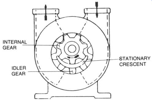
FIG. 19 Internal gear pump. (Dresser-Worthington, Harrison, NJ)
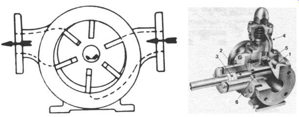
FIG. 20 Sliding vane pump. 1 - nonmetallic or metallic vanes; 2 - bearing
area, internal or external to fluid pumped; 3 - soft packing or mechanical
face seal area; 4 - safety valve; 5 - casing (could be jacketed); 6- rotor.
(Foster Pump Works, Inc., Westerley, RI)
As the internal gear rotates, the idler (external) gear follows and liquid is displaced between the internal gear in the crescent and between the idler and the crescent.
This type of pump is generally used for lower pressure applications at low speeds and it’s generally a cantilever design.
The vane type category of rotating positive displacement pumps consists of external vane types or sliding vanes, as shown in FIG. 20. The vane (or vanes) may be in the form of blades, buckets, or slippers, with a cam to draw fluid into and force it out of the pump chamber.
In the sliding vane pump, the rotor is slotted and a series of vanes follow the bore of the casing. Liquid is displaced between the vanes. This is a slow speed design and it does have lower viscosity limits than gear pumps. The vanes are, however, self-compensating for wear, and this pump, unlike a close-clearance gear design, can be used on mildly erosive liquids.
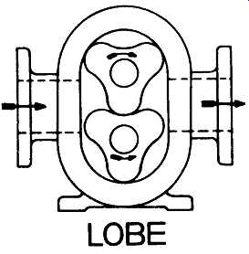
FIG. 21 Lobe-type pump. (Dresser-Worthington, Harrison, NJ)
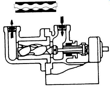
FIG. 22 Single-screw pump and progressive cavity detail. (Sources: Dresser-Worthington,
Harrison, N J, and Netzsch Inc., Exton, PA)
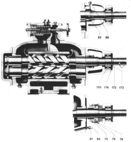
FIG. 23 Twin-screw pump. 62* - mechanical seal; 69 + - locking screw; 72
+* - gland; 75 - gland; 76 + - screw; 81 - adjusting screw; 82 + - cap nut;
170 +* - ball bearing; 172 - supporting disk; 173 +* - circlip-driving spindle-drive
side; 174 + - circlip- cover-drive-side; + - spare parts; * - DIN parts. (Leistritz
Pump Corporation, Allen- dale, N.J)
In lobe type pumps, FIG. 21, liquid is carried between the rotor lobe surfaces from the inlet to the outlet. Since the lobes cannot drive each other, external timing gears are necessary. This type is a low-speed, high-displacement, low-pressure pump popular for marine or highly viscous, low-pressure process applications. There is little difference between lobe-type pumps and the lobe type blowers discussed in Section 15 of this text.
In single-screw pumps ( FIG. 22), the liquid is carried between the rotor screw threads and axially displaced as the rotor threads mesh with internal threads on the stator. This design is versatile in that the rotor and the stator can be made of many different materials so the pump can be used on certain abrasive and corrosive services. Single-screw pumps are sometimes called progressive cavity pumps and are most successfully used in the food processing industries.
Multiscrew pumps are self-priming rotary displacement pumps. Theoretically speaking, they operate like a piston pump with strokes of infinite length. Numerous variations are available. In FIG. 23, a, two-flight driven spindle closely engages and rotates with a three-flight driven spindle. Both are located in a close-fitting casing. In combination, screws and casing form perfectly sealed chambers. The material confined in these chambers is continuously advanced without undue shear force and turbulence.
Peristaltic Pumps
Peristaltic pumps are positive displacement pumps incorporating a flexible hose.
The model shown in FIG. 24, essentially a development of the conventional peristaltic pumping concept, is glandless and valveless. The liquid passes straight through the pump without restrictions. Three main components produce the pumping action- a rotor with three rollers and a smooth-bored flexible hose tube element with the addition of a flexible rubber separator element. The separator is attached to the top of the pump casing, creating a vacuum on the suction side. The hose tube passes directly through the pump between inlet and outlet interposed between the separator and the bottom of the casing. Each roll/squeeze movement of the roller displaces the pumped liquid while the vacuum surrounding the tube on the suction side ensures that it regains shape instantly when the pressure is released. This rapid tube recovery feature enhances and accelerates the normal suction effect of the roll/squeeze peristaltic movement and confers on the pump its exceptional suction characteristics. It allows the use of thin-walled tubes that create a high RPM/volume range. Peristaltic pumps are suitable for liquids, slurries, and gases. Different hose materials accommodate the various feed streams.
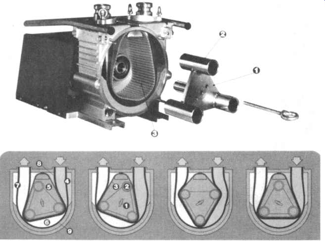
FIG. 24 Peristaltic pump, exploded view and sequence of operation. The rotor
(1) with three rollers (2) rotates within a stationary separation belt
(3) (see exploded view on the top). The separation belt (3) seals the outer
space (4) on the suction side from the inner space (5). The outer space (4)
is sealed on all sides and during rotation, the intake hose (8) is surrounded
by a vacuum that increases the hose volume, causing a suction effect.
The hose volume in space (6) remains constant and the hose volume in space (7) is reduced, which effects a pumping action. The sealed housing holds approximately 1 1/2 quarts of light paraffin-base oil that acts as a lubricating, blocking, and cooling agent. The vacuum gauge indicates the vacuum existing in space (4) and also inside the intake hose (8). The hose support (9) is an elastomer selected to withstand abusive action of foreign matter. (National Mastr Pump, Inc., Houston, TX)
SUB-SECTION A: Principles of Operation of Reciprocating Pumps
How a Reciprocating Pump Works A reciprocating pump is a positive displacement mechanism with liquid discharge pressure being limited only by the strength of the structural parts. Liquid volume or capacity delivered is constant regardless of pressure, and is varied only by speed changes.
Characteristics of a reciprocating pump are 1)positive displacement of liquid, 2)high pulsations caused by the sinusoidal motion of the piston, and 3)high volumetric efficiency.
Plunger or Piston Rod Load
Plunger or piston "rod load" is an important power end design consideration for reciprocating pumps. Rod load is the force caused by the liquid pressure acting on the face of the piston or plunger. This load is transmitted directly to the power frame assembly and is normally the limiting factor in determining maximum discharge pressure ratings. This load is directly proportional to the pump gauge discharge pressure and proportional to the square of the plunger or piston diameter.
Occasionally, allowable liquid end pressures limit the allowable rod load to a value below the design rod load. IT IS IMPORTANT THAT LIQUID END PRESSURES DO NOT EXCEED PUBLISHED LIMITS
Calculations of Volumetric Efficiency
Volumetric efficiency (Ev) is defined as the ratio of plunger or piston displacement to liquid displacement. The volumetric efficiency calculation depends upon the internal configuration of each individual liquid body, the piston size, and the compressibility of the liquid being pumped.
Tools for Liquid Pulsation Control, Inlet and Discharge
Pulsation Control Tools ("PCT", often referred to as "dampeners" or "stabilizers") are used on the inlet and discharge piping to protect the pumping mechanism and associated piping by reducing the high pulsations within the liquid caused by the motions of the slider-crank mechanism. A properly located and charged pulsation control tool may reduce the length of pipe used in the acceleration head equation to a value of 5 to 15 nominal pipe diameters. The pulsation control tools are specially required to compensate for inadequately designed or old/adapted supply and discharge systems.
Acceleration Head
Whenever a column of liquid is accelerated or decelerated, pressure surges exist. This condition is found on the inlet side of the pump as well as the discharge side. Not only can the surges cause vibration in the inlet line, but they can restrict and impede the flow of liquid and cause incomplete filling of the inlet valve chamber. The magnitude of the surges and how they will react in the system is impossible to predict without an extremely complex and costly analysis of the system. Since the behavior of the natural frequencies in the system is not easily predictable, as much of the surge as possible must be eliminated at the source. Proper installation of an inlet pulsation control PCT will absorb a large percentage of the surge before it can travel into the system. The function of the PCT is to absorb the "peak" of the surge and feed it back at the low part of the cycle. The best position for the PCT is in the liquid supply line as close to the pump as possible, or attached to the blind flange side of the pump inlet. In either location, the surges will be dampened and harmful vibrations reduced.
REQUIRED FORMULAE AND DEFINITIONS
Acceleration Head
LVNC GPM ha- V Kg (2.45)(D) where ha = Acceleration head (in feet)
L = Length of liquid supply line (in line)
V = Average velocity in liquid supply line (in fps)
N = Pump speed (revolutions per minute)
C = Constant depending on the type of pump
C = 0.200 for simplex double-acting
= 0.200 for duplex single-acting
= 0.115 for duplex double-acting
= 0.066 for triplex single or double-acting
= 0.040 for quintuplex single or double-acting
= 0.028 for septuplex, single or double-acting
= 0.022 for nonuplex, single or double-acting
K = Liquid compressibility factor
K = 2.5 For relatively compressible liquids (ethane, hot oil)
K = 2.0 For most other hydrocarbons
K = 1.5 For amine, glycol and water
K = 1.4 For liquids with almost no compressibility (hot water)
g = Gravitational constant = 32.2 ft/sec 2
d = Inside diameter of pipe (inches)
Stroke One complete uni-directional motion of piston or plunger.
Stroke length is expressed in inches.
Pump Capacity (Q)
The capacity of a reciprocating pump is the total volume through-put per unit of time at suction conditions. It includes both liquid and any dissolved or entrained gases at the stated operating conditions. The standard unit of pump capacity is the U.S. gallon per minute.
Pump Displacement (D)
The displacement of a reciprocating pump is the volume swept by all pistons or plungers per unit time. Deduction for piston rod volume is made on double acting piston type pumps when calculating displacement. The standard unit of pump displacement is the U.S. gallon per minute.