AMAZON multi-meters discounts AMAZON oscilloscope discounts
There are two main types of centrifugal pumps in process plant service: volute pumps and turbine pumps. The former is more common. Some important pump types, applications and ratings are listed in TBL. 1.
Although pump designs have not progressed as noticeably as gas turbine development, innovative manufactures are constantly finding ways to "do a dirty or difficult job for less cost". This is particularly true in applications where abrasive, corrosive, variable content (in terms of liquid versus solid percentage), and variable flows are concerned. As industry becomes more diverse, it becomes more practical to consider models that have fewer moving parts, and avoid more expensive (often larger capacity) conventional designs that have some "universal" (common to all applications) features. In "universal" applications, main components such as casing and impeller dimensions might be identical. Other components, such as special seals to handle hazardous fluids, wear plates and rings to handle erosive particles are then added to adapt the pump for the application. The reader is therefore encouraged to use TBL. 1 as the basis for exploring different manufacturers and new proven designs when plant expansion or retrofit needs so dictate.
This is an increasingly competitive market, however. Hence, the operator might save on initial capital as well as operational and maintenance costs and yet retain operational flexibility for variable flows by selecting smaller, less expensive units that are tailored for very specific applications.
===
TBL. 1
Pump Type Typical Services Typical Ratings
ANSI Process Corrosive/abrasive liquids, slurries, and solids, high temperature, general purpose pumping process and transfer.
Q to 4500 GPM (1022 m^3/h)
H to 730 ft (222 m)
T to 700~ (371 ~ H to 375 PSIG (2586 kPa)
Nonmetallic Chemical Process Severe corrosives. Q to 800 GPM (182 m3/h)
H to 490 ft (149 m)
T to 300~ (150~ P to 225 PSIG (1550 kPa)
Self-priming Process
Corrosive/abrasive liquids, slurries, and suspensions, high temperature, industrial sump, mine dewatering, tank car unloading, bilge water removal, filter systems, chemical transfer.
Q to 1500 GPM (340 m3/h)
H to 375 ft (114 m)
T to 500 ~ F (260 ~ Suction Lifts to 25 ft (7.6 m)
In-line Process
Process, transfer and general service.
Corrosive and volatile liquids. High temperature services.
Q to 1500 GPM (340 m3/h)
H to 700 ft (207 m)
T to 500 ~ (260 ~ P to 375 PSIG (2586 kPa)
Canned motor Zero leakage services: toxic liquids, refrigerants, liquefied gas, high temperature heat transfer, explosive liquids, liquids sensitive to atmosphere, sphere, carcinogenic and other hazardous services.
Q to 2500 GPM (568 m3/h)
H to 1400 ft (427 m)
T to 700~ (371 ~ P to 450 PSIG (3103 kPa)
API Process (Horizontal)
-/l ll Ii High temperature and high pressure services, offsite, transfer, heat transfer liquids.
Q to 7500 GPM (1700 m3/h)
H to 1100 ft (335 m)
T to 800 ~ (427 ~ P to 870 PSIG (6000 kPa)
API Process (In-line)
Petrochemical, chemical, refining, offsite, gasoline plants, natural gas processing, general services.
Q to 7500 GPM (1700 m3/h)
H to 750 ft (229 m)
T to 650 ~ (343 ~ P to 595 PSIG (4100 kPa)
Paper Stock/High Capacity Process
"Roto Jet" R (registered trade mark)
Paper stock, solids and fibrous/stringy materials, slurries, corrosive/abrasive process liquids.
Medium consistency (8 to 14%) paper stock.
Meets API 610. Pulp and paper, mining, oil, steel mills, petrochemical, boiler feed and desuperheating, central cleaning systems, hydraulic systems, reverse osmosis, spraying systems, transfer, water injection
Q to 28,000 GPM (6360 m3/h)
H to 350 ft (107 m)
T to 450~ (232 ~ P to 285 PSIG (1965 kPa)
Q to 1800 TPD (1650 MTPD) H to 400 ft (125 m)
T to 250~ (120 ~ Q to 400 GPM T to 550F P to 2250 psi
Horizontal (Abrasive Slurry) Corrosive/abrasive services. Coal, fly ash, mill scale, bottom ash, slag, sand/gravel, mine slurries. Large solids.
Q to 10000 GPM (2273 m3/h)
H to 350 ft (107 m/Stage)
T to 400~ (204 ~ P to 300 PSIG (2068 kPa)
Spherical solids to 4" (102 mm)
Axial Flow Continuous circulation of corrosive/ abrasive solutions, slurries and process wastes. Evaporator and crystallizer, reactor circulation, sewage sludge recirculation.
Q to 200,000 GPM (35,000 m3/h)
H to 30 ft (9 m)
T to 350~ (180~ P to 150 PSIG (1034 kPa)
Solids to 9" (228 mm)
Large Solids Handling (Horizontal)
(Vertical Dry Pit)
Pumps for extra demanding municipal and industrial services; large pulpy and fibrous solids, sewage, abrasives.
Q to 100,000 GPM (22,700 m^3/h)
H to 240 ft (73 m)
T to 202 ~ (43 ~ P to 300 PSIG (2065 kPa)
Solids to 10" (254 mm)
Double suction Cooling tower, raw water supply, booster service, primary and secondary cleaner, fan pump, cooling water, high lift, low lift, bilge and ballast, fire pumps, river water brine, sea water, pipelines, crude.
Q to 72,000 GPM (16,300 m^3/h)
H to 570 ft (174 m)
T to 350 ~ (177 ~ P to 275 PSIG (1896 kPa)
Multi-stage Refinery, pipeline, boiler feed, descaling, crude oil charging, mine pumping, water works ... other high pressure services.
Water, cogeneration, reverse osmosis, booster service, boiler feed, shower service.
Boiler feed, mine dewatering and other services requiring moderately high heads.
Q to 3740 GPM (850 m3/h)
H to 6000 ft (1824 m)
T to 375 ~ (190~ P to 2400 PSIG (16,546 kPa)
Low Flow/High Head Multi-Stage Moderate speed
Reverse osmosis descaling, high pressure cleaning, process water transfer, hydraulic systems, spraying systems, pressure boosters for hi-rise buildings, all low flow applications where efficiency is critical.
Q to 280 GPM (64 m3/h)
H to 2600 ft (792 m)
T to 400 ~ (204 ~ P to 1100 PSIG (7584 kPa)
Submersible 9 Wastewater
++ Solids Handling
++ Slurry
Flood and pollution control, liquid transfer, sewage and waste removal, mine dewatering, sump draining.
Large stringy or pulpy solids.
Abrasive slurries.
Q to 4000 GPM (910 m3/h)
H to 210 ft (65 m)
T to 140 ~ (60 ~
Solids to 2" (50 mm)
Vertical Submerged (Submerged Beating and Cantilever)
++ Process
++ Solids Handling
++ Slurry
Industrial process, sump drainage, corrosives, pollution control, molten salts, sewage lift, wastewater treatment, extremely corrosive abrasive slurries, large or fibrous solids.
Q to 7500 GPM (1703 m3/h)
H to 310 ft (95 m)
T to 450 ~ (232 ~ Solids to 10" (254 mm)
Vertical Turbine
Irrigation, fire pumps, service water, deep well, municipal water supply, mine dewatering, cooling water, seawater and river water intake, process, utility circulating, condenser circulating, ash sluice, booster, petroleum/refiner, boiler feed, condensate, cryogenics, bilge, fuel oil transfer, tanker and barge unloading.
Q to 150,000 GPM (34,065 mm3/h)
H to 3500 ft (1070 m)
T to 700~ (371 ~
Vertical mixed flow variable pitch vane General Service (Frame-mounted)
As for vertical turbines Close Coupled and frame-mounted pumps for water circulation, booster, OEM packages, irrigation, chemical process, transfer, and general purpose pumping.
Q to 570,000 GPM H to 80 ft Discharge bore to 158" Q to 2100 GPM (477 m3/h)
H to 400 ft (122 m)
T to 300 ~ (149 ~ (Close-coupled)
===
In the case of turbine pumps, one welcome development has been the development of variable vane pumps. Large power savings of over 20% are realized, greater flow variations with an increase in upper volume transmitted are possible, giving the turbine pump access to further fields of application (see Sub-section 7D). Also, the rotor dynamic problems associated with many turbine pumps that stem from configuration-related vibratory behavior, have been more thoroughly investigated. This has helped eliminate some of the maintenance problems that formerly burdened operators and prompted selection of other types of pumps.
One study into the "reed frequency" (bending mode associated) is described in Sub-section 7C. As was mentioned, the innovative variable vane design means fewer moving parts and lowered required spares inventory. Its wide operating range allows it to be used in a variety of process industries (see TBL. 1). Environmental considerations also play a major role in equipment selection nowadays. Due to space considerations, this topic will be dealt with in Environmental Engineering and Management: Sustainable Development in the Power Generation, Oil & Gas and Process Industries (Butterworth-Heinemann, 1998)
CONVENTIONAL PROCESS PUMPS
FIG.1 depicts a typical American National Standards Institute (ANSI) process pump, which is typical of conventional process pumps. ANSI standards for pumps are dimensional standards that facilitate pump and component interchangeability. As illustrated in FIG.2, this standard dimension process pump is furnished with a fully open impeller, generally preferred for solids handling and for stringy or abrasive-containing pumpage. Two different sealing arrangements are shown: soft packing above the pump centerline, and a mechanical face seal below the pump centerline. FIG.3 illustrates an enhanced ANSI pump with an elastomer bellows seal shown above the pump centerline and a conventional multispring seal shown below the centerline. There are literally hundreds of mechanical-seal types available to serve the numerous different pumps and pumped fluids. Some of these will be described later in this text.
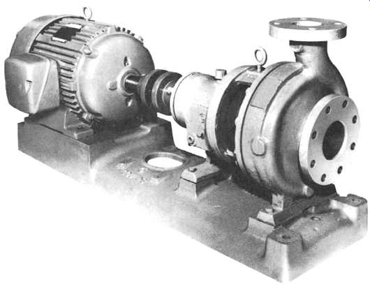
FIG.1 Standard dimension process pump (ANSI).
FIG.4 depicts a between-bearing pump with a double-flow impeller.
Chosen for high-flow capability and balanced axial thrust, double-flow impellers are widely used in large or heavy-duty process pumps. Where maximum accessibility to pump parts and flanges is needed, the user may opt for vertical mounting, as illustrated in FIG.5.
Multistage horizontal split case pumps ( FIG.6) are used for a wide range of moderate- to high-pressure services in process plants. Their typical internal construction features are seen in FIG.7. The pump suction nozzle is on the left. Pumpage leaving the third impeller is routed to the suction of the fourth impeller, located at the opposite end of the pump. This internal flow arrangement results in axial rotor thrust balance by hydraulic means. The external piping ensures pressure equalization between the space to the right of the balancing drum near the entry to stage 4, and to the left of the suction eye of stage 1.
A multistage centrifugal pump with barrel-type outer casing is depicted in FIG.8. These pumps are primarily used for high-pressure and extreme-pressure light hydrocarbon liquids, although certain boiler feedwater services often use this casing style also.
Conventional low flow-high head centrifugal pumps are typically con figured as shown in FIG.9. The multistaging is achieved by adding modular elements that are designed for maximum interchangeability and minimum spare parts i equhemeuts.
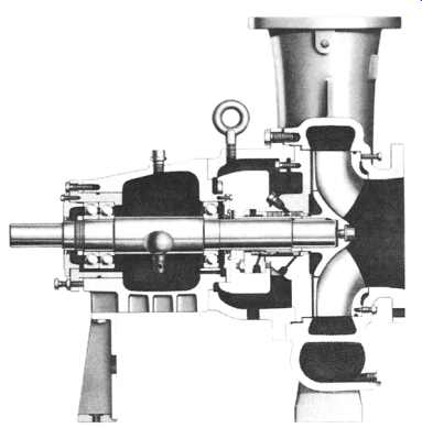
FIG.2 Pump cross section showing typical seal areas.
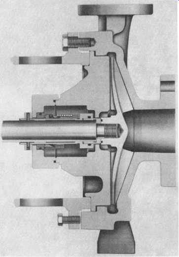
FIG.3 Enhanced ANSI pump showing oversized seal housing and two different
mechanical seals.
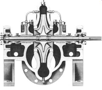
FIG.4 Between-bearing pump with double-suction impeller (single stage).
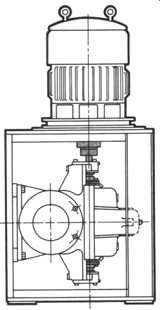
FIG.5 Vertically mounted double-suction pump.
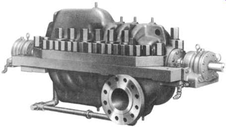
FIG.6 Multistage horizontally split case process pump.
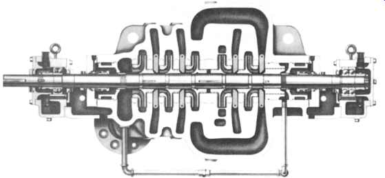
FIG.7 Internal component arrangement of a five-stage horizontally split
case pump.
The particular model illustrated here achieves sealing of the casing by the use of O- tings and long external tie bolts. An alternative execution, which uses a containment casing instead of the tie bolts, is shown in FIG.10.
High-speed pumps for low-flow high-head services are substantially different from conventional low-flow high-head centrifugals and merit special coverage.
These pumps are described later in this section.
The construction features of submersible wastewater pumps are shown in FIG.11. These pumps obviously have to be capable of occasional solids ingestion, which makes it necessary to design and build the impeller with suitable features.
Close-coupled and frame-mounted pumps are primarily designed for general purpose pumping. Quite similar to the close-coupled vertical pump, close-coupled and frame-mounted pumps have the impeller placed on the electric motor shaft.
Large solids-handling pumps are manufactured in a variety of configurations.
FIG.12 shows a horizontally arranged model. Accessibility for service and general ease of maintenance are important for this pump category.
In self-priming process pumps, priming and air separation are accomplished within the pump casing. The pump is designed with two volutes; these are separate stationary channels into which the rotating impeller pushes the pumpage exiting from the impeller tip. During the priming cycle, the lower volute functions as the intake while the upper volute discharges liquid and entrained air into a separation chamber.
Air is separated and expelled through the pump discharge while liquid circulates into the lower volute. Once air is completely exhausted from the suction region and liquid fills the impeller eye, the pump is primed and functions as a conventional pump, with both volutes acting as discharges. As shown in FIG.13, the casing is designed so that an adequate volume of liquid for repriming is always retained in the pump, even if liquid is allowed to drain back to the source of supply from both discharge and suction.
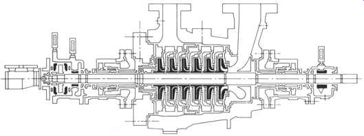
FIG.8 Multistage barrel casing-type centrifugal pump. (Sulzer Brothers,
Winterthur, Switzerland.)
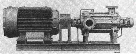
FIG.9 Conventional low-flow, high-head centrifugal multistage pump made
up of modular elements.
FIG.10 Low-flow, high-head three-stage centrifugal pump with containment casing.
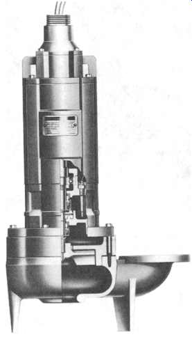
FIG.11 Submersible wastewater pump.
The function of a dual volute design is shown in FIG.14. The dual volute casing design is ideal where pumps must periodically operate at capacities above or below design capacity or at uninterrupted high head. Essentially, this design equalizes radial forces and lessens radial reaction on shaft and beatings. This equalization or balancing of radial forces is accomplished by dividing the liquid discharged by the impeller into two half-capacity volutes with two cutwaters, set 180 degrees apart. Radial forces on the shaft and bearings are equally opposed.
In-line process pumps are vertically oriented pumps with the casing designed to bolt directly into the piping system. They require a min. of support from a relatively small foundation or similar structure and have proven to be as reliable and easy to maintain as conventional, horizontally oriented centrifugal pumps.
FIG.15 shows an in-line pump with flexibly coupled electric motor shaft to pump shaft connection. The pump has its own bearing support whereas the so-called close-coupled in-line pump shown in FIG.16 uses a rigid coupling sleeve and has its rotor supported by the electric motor bearings only. Although the flexibly coupled and close-coupled styles are generally equally reliable, the flexibly coupled version should be preferred from an ease-of-maintenance point of view. A third variation of the in-line pump construction has the pump impeller placed on the motor shaft end. This style is found less often in process plants.
American Petroleum Institute (API) process pumps get their name from an API standard (API-610) that specifies the requirements for this heavy-duty pump. While statistics show that properly applied ANSI pumps have a useful life and reliability matching that of API pumps, the latter nevertheless has some construction features that […].
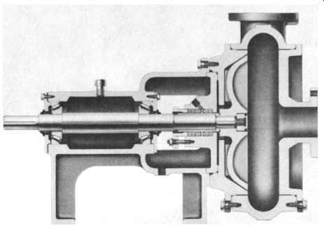
FIG.12 Large solids handling pump with vortex impeller.
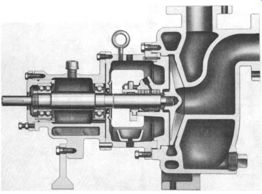
FIG.13 Self-priming process pump.
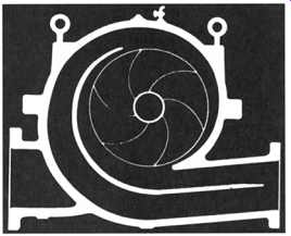
FIG.14 Principle of dual volute design. The dual volute casing design is
ideal where pumps must periodically operate at capacities above or below
design capacity or at uninterrupted high head. Essentially, this design equalizes
radial forces and lessens radial reaction on shaft and bearings. This equalization
or balancing of radical forces is accomplished by dividing the liquid discharged
by the impeller into two half-capacity volutes with two cut-waters set
180 degrees apart. Radial forces on the shaft and bearings are equally opposed.
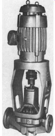
FIG.15 Vertical in-line pump with flexibly coupled electric motor. (Goulds
Pumps, Inc., Seneca Falls. NY.)
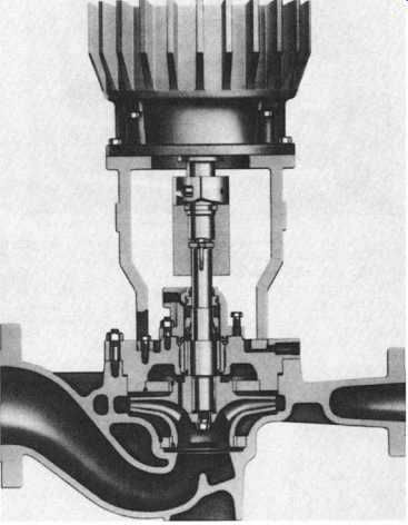
FIG.16 Rigid spacer-coupled vertical in-line pump.
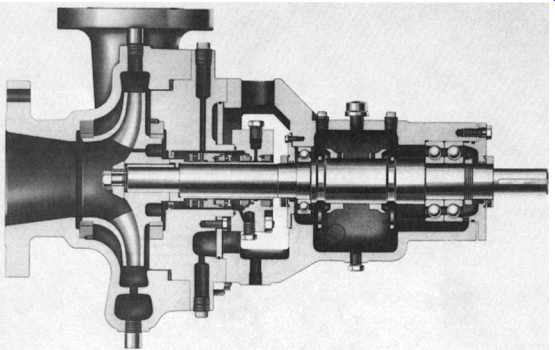
FIG.17 Single-stage back pull-out-type centrifugal process pump complying
with API SPEC 610.
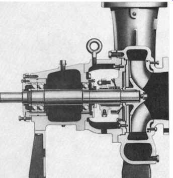
FIG.18 Heavy-duty process pump for paper stock incorporating repeller arrangement
to reduce load on stuffing box area.
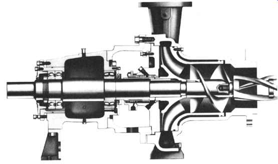
FIG.19 Paper stock pump incorporating special inducers.
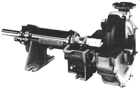
FIG.20 Typical slurry pump.
API pumps differ from ANSI in the following respects"
++ API pumps have greater corrosion allowance.
++ They have higher permissible nozzle loads.
++ API pumps have more available stuffing box space.
++ Wear tings are furnished in API pumps. They are not always supplied with ANSI pumps.
++ API pumps are centerline-mounted; ANSI pumps are often foot-mounted.
++ Bearing housings in API pumps are generally fitted with higher load capacity bearings and higher life expectancy end seals.
FIG.17 illustrates a typical API process pump.
Paper stock and high-capacity process pumps are typically con figured as shown in FIGs. -18 and 7-19. Both pumps incorporate wear plates opposite the open side of the impeller. Maintainability and simplicity of construction are key requirements in these services. FIG.18 incorporates a repeller arrangement to oppose the and a rotating part. FIG.19 depicts a model that incorporates special inducers to accommodate difficult pumpage.
In a "Roto-Jet ''R pump, liquid enters the manifold and passes into the rotating case where centrifugal force causes the liquid to accelerate and enter the rotor under pressure. The velocity energy of the liquid in the rotor is converted into additional pressure as it jets into the pick-up tube. The liquid flows through the pick-up tube and is discharged.
This design results in a wide operating range with low minimum flow. The differential head can be adjusted by changing speed. The capacity can be adjusted by changing the pick-up tube size.
Only two working-parts are the basis for this true one stage design: a rotating casing driven by an oversize shaft, and a stationary pick-up tube mounted in the manifold.
(See also Sub-section 7E) A typical slurry pump is shown in FIG.20. Resistance to corrosion and wear is of great importance in slurry pumps, and simple construction aids in making the pumps maintainable. In some pumps, replaceable rubber lining is used on the wetted parts.
Much of the confusion in deciding when to specify a slurry pump arises from the lack of agreement on the meaning of the word slurry. This is due in large part to the nearly infinite number of solid-liquid mixes. In place of the many academic slurry definitions, this broader, more functional definition is offered: A slurry is any mixture of liquid and solids capable of causing significant pump abrasion, clogging, or mechanical failure due to high loads or impact shocks.
Under some circumstances, it may seem superfluous to consider the "when" of slurry pump selection. Obviously, a pump employed to move "deliberate" slurries such as mine tailings or chemical concentrates must be designed and constructed with exceptional strength, abrasion resistance, and solids-passage ability.
But what about a pump employed to supply large quantities of water from a sandy fiver for cooling purposes? In such "accidental" slurries, the transport of liquids is the prime purpose- the presence of solid materials is not intended (or, sometimes, even recognized). Nevertheless, failure to use a slurry pump for this type of application can frequently result in excessive maintenance, parts usage, and downtime costs.
The "when" of slurry pump selection might best be answered by a rule of thumb that says that whenever the fluid to be pumped contains more solids than are found in potable water, at least consider the use of a slurry pump.
There are many features that set a slurry pump apart from a standard, general service centrifugal pump. Outwardly, there are few differences, although the slurry pump is usually larger in size. Internally, however, there are many characteristics that make a slurry pump a very specialized breed.
Wall thickness of wetted-end parts (casing, impeller, etc.) are greater than those used in conventional centrifugal pumps. The cutwater, or volute tongue (the point on the casing at which the discharge nozzle diverges from the casing), in the casing is generally less pronounced in order to minimize the effects of abrasion. Flow passages through both the casing and impeller are large enough to permit solids to pass without clogging the pump. Slurry pumps are available in a variety of materials of construction to best handle the abrasive, corrosive, and impact requirements of nearly any solids-handling application.
Because the gap between the impeller face and suction liner will increase as wear occurs, the rotating assembly of the slurry pump must be capable of axial adjustment to maintain the manufacturer's recommended clearance. This is critical if design heads, capacities, and efficiencies are to be maintained. Other specialized features include extra-large stuffing boxes, replaceable shaft sleeves, and impeller back vanes that act to keep solids away from the pump stuffing box.
Both radial and axial-thrust bearings on the slurry pump are generally heavier than for standard centrifugals, owing to the demands imposed by slurries of high specific gravity. Although impeller back vanes (used to lower stuffing box pressures) do actually reduce axial thrust, these vanes can wear considerably in abrasive services. Consequently, the bearings must be of ample capacity to handle thrust loads by themselves. Balancing holes through the impeller should not be used to reduce axial thrust, since they can either clog or initiate excessive localized impeller wear.
Nearly all slurry pumps have larger diameter impellers than units for pumping clear liquids, enabling heads and capacities to be met at reduced rotational speed.
Low-speed operation is one of the most important wear-reducing features of a slurry pump. In fact, experience shows that abrasive wear on any given pump rises at least with the third power of RPM increase.
An analysis of the static profile of the slurry pump will help determine the solids-passage ability, abrasion resistance, and mechanical strength required of the pump. The most important elements in the static profile can be assigned to four categories:
1. Size of the solids: What are the largest particles the pump must handle? Are these solids similar or random in size?
2. Nature of the solids: Are they pulpy or hard, light or dense, round or jagged? Are they abrasive or corrosive?
3. Nature of the liquid: How corrosive is the liquid? Will it lubricate the solids and reduce abrasion?
4. Concentration of the solids: It’s the ratio of solids to liquids that determines how the characteristics of the solids will influence the slurry as a whole.
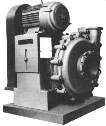
FIG.21 Pump designed to handle industrial and municipal wastewater.
These four static characteristics create unique demands, requiting specific pump design and construction features. For example, FIG.21 shows a pump model designed to handle wastes, light slurries, and random large solids. Unlike the slurry pump discussed earlier, this unit does not use wear liners. The emphasis here is on very large flow passages through the casing and impeller. Because such units are generally used for pumping sewage, light slurries, and relatively nonabrasive industrial wastes, certain wear-reducing design features can be compromised to increase hydraulic efficiency.
When chemical sludges or wastes containing large solids must be pumped, a vortex pump is often the best answer. Because its impeller is fully recessed into the rear of the casing, a relatively small pump can be used to handle liquids containing very large solids. A vortex pump was shown earlier in FIG.12.
Still other slurries may exchange the problems of large solids for the equally difficult pumping idiosyncrasies associated with high concentrations of small solids.
More often than not, such slurries present extreme abrasion problems. Typical are those associated with lime slurry pumping, the handling of ore concentrates, kaolin clay, or cement slurries. FIG.22 shows an extremely heavy-duty slurry pump ideal for such applications.
FIG.23 represents only one of numerous styles of vertical sump and process pumps. Also see Sub-section 7D. This particular model has the discharge piping attached to the bowl assembly. Also, this model is shown with externally connected tubing for the lubrication of line shaft bearings. Depending on the nature of the service, a process plant may be best served by vertical industrial turbine pumps similar to those shown in FIG.24.
The vertical pump shown in FIG.24 has either a fabricated or cast discharge head and either a threaded or flanged column. It’s designed for clean, noncorrosive liquids, at low to medium pressures. This model is often selected when lowest initial cost is of prime consideration. Its principal applications are irrigation, fire water services, service water and deep well pumping, drainage, and municipal water supply.
The Use of a flanged column on pumps of the type shown in FIG.24 facilitates maintenance, and a good selection of additional line shaft bearing materials is often available for these pumps. They are primarily used in low- to medium- pressure effluent, oily wastewater, and mine dewatering applications.
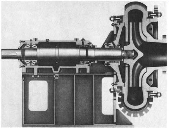
FIG.22 Very heavy-duty pump for slurries with large concentrations of highly
abrasive particles.
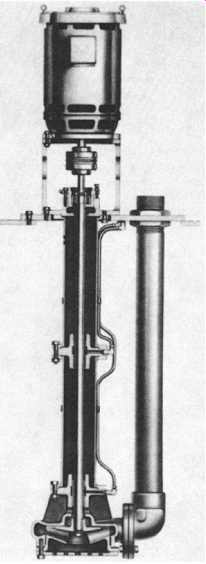
FIG.23 vertical sump and process pump.
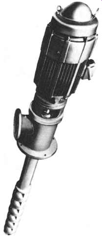
FIG.24 Typical vertical turbine pump with principal application in water
services.
Vertical industrial turbine pumps that incorporate both a fabricated discharge head and flanged column are designed for high-pressure applications, when ease of maintenance is a prime consideration, or when alloy materials of construction are required for corrosive and/or erosive services. These pumps would also be suitable for a wide range of pumping temperatures, if used in industrial processes. However, they are primarily used in cooling water, sea and fiver water intake, utility circulating water, condensate, and ash sluice water services.
A vertical can-type pump is depicted in FIGs. -25 and 7-26. Using a fabricated discharge head and barrel and a flanged column, the pump is designed for low net positive suction head (NPSH) available and subatmospheric suction pressure services. Typical applications are pipeline boosters, product unloading, refinery blending, injection/secondary recovery, ammonia transfer, condensate, cryogenic, and liquid natural gas (LNG) transfer duties.
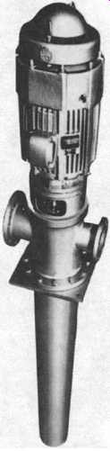
FIG.25 Vertical can-type turbine pump, shown with fabricated head principally
used in hydrocarbon processing services.
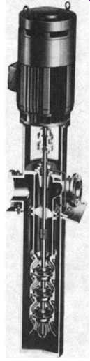
FIG.26 Cross section of vertical can-type pump.
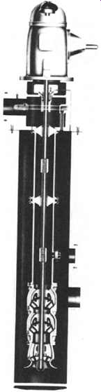
FIG.27 Vertical marine pump with fabricated discharge head, flanged column,
and right angle gear drive.
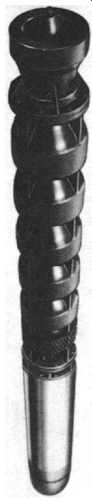
FIG.28 Vertical industrial submersible pump for deep-well applications.
FIG.27 shows a vertical marine pump that uses a fabricated discharge head and flanged column. Pumps of this type are often designed to be self-priming and to efficiently unload or strip product tankers and tank barges. They have also been applied as ship firewater pumps, ballast pumps, bilge pumps, and fuel oil transfer pumps.
In our next illustration, FIG.28, we see a vertical industrial submersible pump. This version is used for deep settings or where the use of a lineshaft pump is impractical, e.g., in irrigation, service water, and deep well supply situations.
Finally, there is also a close cousin to the vertical pump- the vertical energy recovery turbine ( FIG.29). The recovery turbine takes high-pressure liquid and converts it into rotating energy that can be used to power other pumps, or other rotating equipment.
Virtually all of the vertical industrial pumps discussed for process plant applications include a variety of features and/or options that are of interest. Take, for instance, the bowl assembly, which is the heart of the vertical turbine pump. The impeller and diffuser-type casings are designed to deliver the head and capacity that a system requires for optimum efficiency. The fact that the vertical turbine pump can be multistaged allows maximum flexibility both in the initial pump selection and in the event that future system modifications require a change in the pump rating. Submerged impellers allow a pump to be started without priming.
A variety of material options allows the selection of a pump best suited for even the most severe services. The many bowl assembly options available assure that the vertical turbine pump satisfies the users' needs for safe, efficient, reliable, and maintenance-free operation. FIG.30 depicts the more important ones.
There exists also a large number of column options (FIG.31), discharge heads ( FIG.32), coupling arrangements (FIG.33), and sealing flexibility options ( FIG.34).
Circulator, or axial flow pumps are shown in FIGs. -35 and 36. Although not strictly centrifugal flow pumps, these high-flow, low-head machines are worthy of mention.
===
UPPER HEAD ELECTRIC MOTOR UPPER ADJUSTABLE COUPLING TURBINE DISCHARGE FLANGE
ENERGY LOWER ~ RECOVERY DISCHAR( HEAD TURBINE PUMP SUCTION IRBINE SUCTION PUMP DISCHARGE
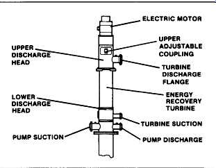
FIG.29 Vertical energy recovery turbine-a vertical pump in reverse rotation.
===
FIG.30 Assembly options for vertical pump bowls.
===
Threaded Column Threaded column is used whenever initial cost is primary consideration. Pipe ends are machine-faced for butt fit between sections to maintain alignment, Threaded column is used where pump length requires numerous column sections such as a deep well application,
OPEN LINESHAFT ASSEMBLY
FIG.31 Vertical pump column assembly options.
===
The discharge head functions to change the direction of flow from vertical to horizontal and to couple the pump to the sys- tem piping in addition to supporting and aligning the driver.
Discharge head accommodates all modes of drivers including hollow shaft and solid shaft motors, right angle gears, vertical steam turbines, etc. Optional sub-base can be supplied.
Goulds offers three basic types for maximum flexibility.
BELOW GROUND DISCHARGE HEAD Used whenever VIT pump Is required to adapt to an under- ground discharge system.
CAST IRON DISCHARGE HEAD Used for low pressures (not exceeding 175 psi) and/or when low initial cost is primary consideration.
FABRICATED DISCHARGE HEAD
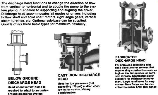
FIG.32 Discharge head arrangements for vertical column pumps. RIGID FLANGED
COUPLING ( Type AR) To couple pump; To vertical hollow shaft driver. Impeller
adjustment is performed on adjusting nut located on top of motor.
ADJUSTABLE COUPLING (Type A) For vertical solid shall driver.
Impeller adjustment made by using adjustable plate in the coupling.
ADJUSTABLE SPACER COUPLING ( Type AS) Same function as type A coupling with addition of spacer. Spacer may be re- moved for mechanical seal maintenance without disturbing driver.
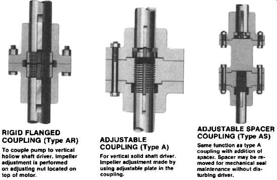
FIG.33
===
PACKED BOX Whenever packing lubrication leakage can be tolerated and the discharge pressure does not exceed 300 psi, a packed box may be used. Optional head-shaft sleeve available to protect shaft.
WATER FLUSH Water flush tube connection is sup- plied when pressurized water is introduced into the enclosing tube for bearing protection on abrasive services.
OIL LUBRICATED Oil lubricated option is recommended when water elevation would cause the upper Lineshaft bearings to run without lubrication during start-up.
Oil is fed thru tapped opening and allowed to gravitate down enclosed tube lubricating bearings.
INSIDE MOUNTED SEALS Most popular method -- used for medium to high pressures. Cartridge style for ease of Installation and maintenance.
OUTSIDE MOUNTED SEALS Provides a method of no-leak sealing follow pressure applications.
TANDEM SEALS Two seals mounted in-line. Chamber between seals can be filled with a buffer liquid and may be fitted with a pressure sensitive annunciating device for safety.
FIG.34 Sealing flexibility options for vertical column pumps.
===
FIG.35 Axial flow or elbow-type (circulator) pump used for high-volume,
low-head applications in process plants.
FIG.36 Principal components of axial flow pumps.
===

FIG.37 Canned motor pump cross section. Note inducer for effective lowering of NPSH requirement.
===
Suitable for handling volatile liquids; ammonia, freon and other liquefied gases.
Same as R-Type but uses an adapter between pump and motor. Allows for greater pump/motor flexibility.
for liquids with high melting point Similar to K-S Type but better suited for fluids with relatively low melting point. FIG.38 Canned motor pump variations for special fluid conditions.
Used for sump and unloading services.
Handles fluids with large amount Of-fine solids. S-Type with external flushing also available.
Suitable for handling high temperature fluids; heat transfer.
Suitable for handling liquids with small amount of fine solids.
FIG.39 Canned motor pumps for unusual fluid conditions.
===
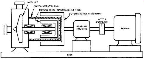
FIG.40 Sealless magnet drive pump with a separately mounted electric motor.
In this installation, the base, the electric motor, and the motor coupling
are identical to parts used in conventional pumps. The difference between
seal-less pumps and conventional pumps occurs in two areas: (1) driving torque
is transmitted magnetically rather than mechanically; and (2) the impeller
drive shaft rides in bushings housed within the pump enclosure rather than
by bearings mounted externally. (Kontro Pump, Orange, MA.)
===
CANNED MOTOR AND SEALLESS MAGNET-DRIVE CENTRIFUGAL PUMPS
Canned motor and sealless drive pumps were developed to contain hazardous, valuable, toxic, or carcinogenic pumpage. These designs avoid the use of mechanical shaft seals and confine the pumpage within a hermetically sealed space.
The canned motor design ( FIG.37) comprises a single shaft that combines the functions of a motor rotor and pump rotor in a single assembly. The motor rotor is surrounded by a stainless steel sleeve that is permeated by the magnetic flux lines generated by the surrounding stator windings.
A large number of variations of the standard canned motor design are available to the user. FIGs. -38 and 39 give an overview that includes canned motor pump models suitable for hot fluids, abrasive liquids, and pumpage close to the vaporization temperature.
A typical sealless magnet drive pump is illustrated in FIG.40. While unique when compared with conventional-design centrifugal pumps, magnet-drive pumps represent a combination of standard components and proven concepts. FIG.40 depicts a typical sealless magnet-drive pump with a separately mounted electric motor drive. In this installation, the base, the electric motor, and the motor coupling are identical to parts used in conventional pumps. The differences between these pumps and conventional pumps are concentrated in two areas:
1. Driving torque is transmitted magnetically rather than mechanically.
2. The impeller drive shaft tides in bushings housed within the pump enclosure rather than on bearings mounted externally.
In FIG.40, the drive motor is coupled directly to the outer magnet ring by a conventional motor-to-pump coupling. The overhung load of the outer magnet ring is carried by the bearings in the bearing housing. FIG.40 also shows that the impeller is mounted on the same shaft as the inner magnet rotor, sometimes called the torque ring. The impeller drive shaft is carried by one or two bushings that are within the pumping enclosure. Note that the pump enclosure is formed by the pump casing and the containment shell. The driving torque of the electric motor is transmitted to the pump impeller by the magnetic coupling of the outer magnet ring and the torque ring without breaching the pumping enclosure. It’s this magnetic coupling that replaces the mechanical seals of conventional centrifugal pumps. The efficiency obtainable with canned motor and magnet drive pumps is below that of well-designed, conventional centrifugal pumps. Also, canned motor and magnet- drive pumps may not be available in size ranges much over 100 kw. Nevertheless, they represent viable options that must be evaluated on a case-by-case basis.
HIGH-SPEED CENTRIFUGAL PUMPS
Development of the High-Speed Concept
The term high speed is generally used to classify equipment that operates above two pole motor speeds. Centrifugal pump designs falling into this category have gained considerable acceptance since 1960. The increasing popularity of high-speed pumps has coincided with the expanding need for higher pressures in the process and general industries since World War II. At the same time, improved technology, manufacturing techniques, and materials have facilitated the transition from design theory to production hardware.
The developed head in centrifugal pumps is a function of the tip speed of the impeller and/or the number of impellers employed. There are three principal methods that can be used to achieve higher pressures, and in some cases a combination of these methods may be utilized:
++ Increasing the size of the impeller to increase its peripheral speed. This is a simple and effective method, but only to a point. The practical design limit for impeller diameters is 13 to 16 inches at two pole speeds.
Using a number of staged impellers. Although continued development of multistage pumps has resulted in hydraulic efficiencies approaching single-stage efficiencies, the complexity of the design and close impeller clearances results in high first cost, loss of performance as the clearances wear, and often high maintenance requirements if the pump is subjected to difficult service conditions.
Increasing rotational speed. The practical speed limitations for pumps directly driven by induction motors is 3600 RPM with 60 cycle power and 3000 RPM with 50 cycle power. The rotational speed of electric-driven pumps can, however, be increased by using either higher frequency power or a speed-increasing gearbox.
Since with few exceptions, higher frequency power has not yet become an economically viable approach, the use of gear-driven single-stage, high-speed centrifugal pumps has become widespread.
This segment of our text deals primarily with a unique pump design that has been adapted for operation at higher speeds to produce high heads at low to moderate flow rates. Although high-speed pumps are now widely used in industry, comparatively few design discussions have appeared in print.
An early commercial application of this design concept emerged in 1959, when a high-speed single-stage centrifugal pump was used in aircraft service to augment the thrust in jet engines during takeoff. This pump rotated at 11,000 RPM, delivering 80 gallons per minute of water to the combusters at 400 psi to increase the mass flow rate through the engine, thereby increasing the thrust by 15 percent during takeoff. The unit weighed only 8 89 pounds, including step-up gearing from the 6500 RPM power takeoff pad to pump speed. Some 250 units were produced for this service.
By 1962, the first integrally geared high-speed process pumps were finding their way into the petrochemical and refining industries. In subsequent decades, their use has been greatly expanded, and they are now available from 1 to 2500 HP, utilizing speeds to 32,000 RPM, and producing heads to 12,000 feet. Most commonly, these products consist of a single stage but may employ two or three stages to satisfy the need for extreme heads or the combination of high head and low net positive suction head available (NPSHA). By the early 1970s, the high-speed pump concept had been extended to include a wide variety of services across a broad spectrum of industries.
Unique Design Advantages
The increasing popularity of integrally geared high-speed centrifugal pumps is due to a number of factors:
++ Shaft dynamics. As shaft speeds are increased, the size of the components required for any given condition of service grows smaller. The smaller, more compact design results in shorter shaft spans, lower shaft deflection, and improved shaft dynamics.
++ Reduced size and weight. A high-speed pump with a single six-inch impeller can exhibit the same performance as a multistage pump that uses as many as 40 stages with the same size impellers. The size and weight reduction can be as much as 5 to 1, which of course translates to smaller and less expensive mounting foundations.
++ Fewer parts required. High-speed pumps generally have one stage and occasion- ally two or three stages. This can mean a significant reduction in the number of "wetted" components. In processes requiting exotic metallurgies, this can provide
a substantial capital cost advantage as well as less supporting inventory and lower repair parts costs.
++ High-speed gear-driven pumps can be designed to incorporate many common parts. Seals, bearings, and housings are typically common across a given product line. Only the pump case, impeller, and/or gear ratio need to be changed to provide a wide range of performance. In a plant requiting many of the same types of pumps, the number of spare parts can be reduced.
++ Reduced maintenance. Another benefit realized by the user is simplified maintenance resulting from the reduced size and quantity of parts. Additionally, some high-speed pump designers have allowed for the complete removal and installation of all fluid end components, seals, and bearings in a single modular high-speed shaft assembly (see FIG.41).
++ Performance consistency, The head, flow, and efficiency of many high-speed pumps is resistant to efficiency and head degradation, since open radial bladed impellers don’t require close clearances. In applications where consistency of performance over the life of the pump is desired, a high-speed pump with large running clearances can be very desirable.
FIG.41 Removable high-speed shaft assembly for low-flow high-head pump. (Sundstrand Fluid Handling, Arvada, CO.)
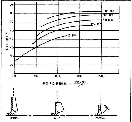
FIG.42 Effect of specific speed on high-speed pump efficiency. (Sundstrand
Fluid Handling, Arvada, CO.)
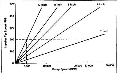
FIG.43 Relationship of pump rotative speed and impeller diameter to tip
speed. Pump Speed (RPM) (Sundstrand Fluid Handling, Arvada, CO.)
Hydraulic Capabilities
High-speed pumps are manufactured in both single and multistage configurations.
Radial vaned open impellers are optimum for low specific speed applications (see FIG.42) from Ns = 150 to Ns = 850. This hardware is capable of achieving 6000 feet in a single stage. Higher flow units typically use Francis vaned impellers with wear rings when the specific speed ranges from 850 to 1860. As impeller speed is increased-to-meet a given and pump efficiency increase, while torque decreases for the same horsepower requirement.
Accordingly, shaft stress, gear, and radial beating loads improve with higher speeds.
The user should not be unduly concerned with increased wear or stress due to higher rotational speeds. The maximum stress level in an impeller is a function of the impeller tip speed. As shown in FIG.43, the stresses at 200 feet per second (FPS) are the same regardless of whether the speed is produced by a 3600 RPM twelve-inch impeller or by a 23,000 RPM two-inch impeller, and shaft deflection and bearing loading are minimized using unusually low overhang ratios and small impeller weights.
As impeller speed increases, the NPSH required for stable operation also increases. Often an axial flow inducer with good suction performance is used in series with the impeller to lower NPSH requirements. It’s attached directly to the shaft in place of the impeller nut. On two- or three-stage machines, the first stage can often be geared at a lower speed for lower net positive suction head required (NPSHR), while the subsequent stages do most of the work.
Mounting Arrangements
The unique design of the high-speed pump lends itself to a variety of mounting configurations. Since the pump first appeared in the industrial market as a single-stage vertical in-line type, the full range of possibilities has been explored.
Today these pumps exist in the following forms to serve a wide range of general industrial and process markets: vertical in-line; horizontal single-stage, two-stage, and three-stage, with both single-step and two-step speed-increasing gearboxes.
High-speed pumps are often available in either close-coupled or frame-mounted configurations. The close-coupled design eliminates the need for coupling alignment and occupies the least amount of floor space, while the frame-mounted units are used whenever conventional driver packages are selected.
Applications Process applications for high-speed centrifugal pumps exist wherever there is a need for medium or higher pressures. Their widespread use is based on adapt- ability to many diverse requirements. High-speed pumps are an essential part of processes utilized in the production of such end items as plastics, pharmaceuticals, petrochemicals, synthetic rubber, and paper. The technology incorporated in these pumps makes them especially suited to lower flow, high-head applications, displacing reciprocating two-stage and multistage pumps as the preferred product.
Users apply high-speed pumps to process applications for numerous reasons, but the primary deciding factor is economics. Economic evaluations typically include first cost, installed cost, operating cost, maintenance cost, and overall evaluated cost.
Each determining factor must be based on the user's specific situation. The primary reasons that high-speed pumps are often selected over reciprocating, single-stage, two-stage, or multistage centrifugals are lower first cost, lower installed cost, and occasionally lower maintenance costs. Operating costs will generally approach those of other centrifugal pumps but are almost always higher than positive displacement pumps with their inherently better mechanical efficiencies. The performance area where the high-speed pump has the greatest advantage is in the low-flow range.
Pump mechanical requirements vary, depending on the critical nature and location of the particular service. In severe or hazardous applications, API-610---For less critical services, however, general service pumps should also be considered. Although many of the same design features are available in both types, the significantly lower cost associated with non-API designs encourages their use in less critical services.
High-speed pumps can be used as the primary pump, as an installed spare for an existing pump, as a boost pump piped in series with another pump, or as a support pump for a seal flush or lube oil. They are utilized in both continuous and standby operation.
It’s not unusual to find high-speed pumps feeding a variety of systems where flow demands are constantly changing. These pumps are especially suited to high- pressure washdown and shower services where multiple sprayers are turned on and off as the system demands change. The controls required to operate these systems are simple and reliable, allowing operation of the pump over most of its performance envelope down to flows as low as 15 percent of the best efficiency point flow.
Process plant applications are as diverse as the industry served. Beginning with power systems, high-speed centrifugal pumps are applied in boiler feedwater, condensate return, desuperheater or attemporator, gas turbine NOX suppression, and reverse osmosis applications.
Process systems use high-speed pumps in a variety of services including but not limited to transfer, seal flush, waste injection or disposal, blending, sampling, recycling, descaling, metering, waste disposal, reactor feed, booster, pipeline, charge, reflux, circulation, bottoms, flare drum knockout, and high-pressure washdown.
Some typical fluids pumped include water, caustics, ammonia, carbamate, fuel oil, naphtha, acids, a majority of hydrocarbons, and chemicals too numerous to mention.
As evidenced by the wide variety of applications, high-speed pumps are a proven product with years of reliable operating experience.
System Controls
The control of high-speed centrifugal pumps is similar to most conventional centrifugal pumps. When specifying the control system, it’s important to consider the allowable operating range of the pump and its hydraulic characteristics, as well as the hydraulic requirements of the process.
There are generally two objectives that need to be kept in mind when designing a control system. One is to protect the pump from damage that can be incurred from operating outside its design operating range. A second is to provide the controls that will enable the pump to meet the needs of the process.
Centrifugal pumps tend to operate over a wide flow range with relatively slight variation in pressure in comparison with positive displacement pumps. The maximum and minimum operating limits for centrifugal pumps with flat performance curves are normally based on flow rather than pressure. Thus the protective controls should be designed to measure and control flow rate rather than discharge pressure (FIG.44). Maximum Flow Limit
Volute-type centrifugal pumps have the lowest bearing radial loads at the design flow rate or best efficiency point. As the flow through the pump is increased or decreased from the best efficiency point, the radial hydraulic loads increase. Also, as flow velocities increase, the potential for impeller cavitation increases. The power also increases with flow. Operation at excessive flows can lead to bearing failures, high shaft stresses and possible failures, and cavitation damage to impellers and casings.
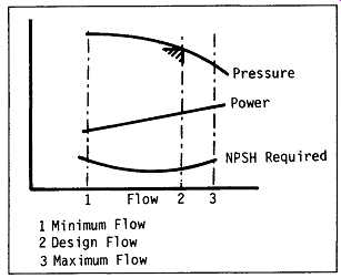
FIG.44 Typical centrifugal pump performance. (Sundstrand Fluid Handling)
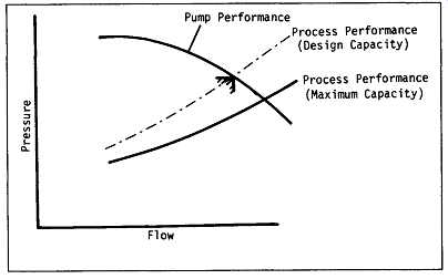
FIG.45 Pump curve matched to process requirements at maximum capacity.
Attention to the maximum flow limit of the pump and knowledge of the process hydraulic characteristics when the pump is specified can result in a process that is self limiting and without need of special controls to prevent excessive flow through the pump. FIG.45 shows a pump curve that has been matched to the process needs at maximum capacity. The initial startup should be carefully planned to allow pipes to empty and vessels to be filled gradually, preventing water hammer or overloading the pump.
Minimum Flow Limit
As flow increases from the design point, beating radial loads generally increase and efficiency decreases. If the flow decreases enough, recirculation can occur and the pump becomes hydraulically unstable. Extensive damage can be done if a pump is allowed to operate for long periods in an unstable condition.
As efficiency decreases at low flow, the rate of temperature rise of the fluid increases. This can be a concern in applications with low available NPSH. The specific minimum flow limit depends partially on the pump and partially on the process (assuming adequate beating capacity). Advertised performance curves generally show minimum flow that is expected with ideal fluid properties and proper inlet and discharge piping. Minimum flow controls should always be checked by observing the pump in operation with the minimum flow control functioning.
Near the minimum flow point, most centrifugal pumps have nearly constant pressure with respect to flow. To prevent operation below the minimum flow limit, the first choice for the measured variable is flow. A control system that prevents operation above a particular maximum discharge pressure does not necessarily ensure minimum flow protection.
When centrifugal pumps are operated in parallel, individual minimum flow control is necessary. A check valve should be installed in the discharge line of each pump. This is to prevent one pump from driving the other pump off its performance curve if both pumps are operating and the process is modulated to a low-capacity condition (see FIG.46). Modulating a bypass line is the normal method for preventing minimum flow.
If the bypass line discharges immediately into the pump suction, the fluid temperature will rise because of the power being dissipated in the pump bypass loop. If prolonged operation with this arrangement is expected, then a maximum temperature trip should be considered ( FIG.47). Suction Pressure Limit
Occasionally a process scheme may allow suction pressure to vary. If variations can cause the NPSH available to fall below that required by the pump, or the inlet pressure to rise above the maximum rated pressure for either the pump or the seal system, appropriate limiting controls will be required.
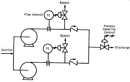
FIG.46 Parallel pumps with individual flow-modulated bypasses for minimum
flow protection. (Sundstrand Fluid Handling, Arvada, CO.)
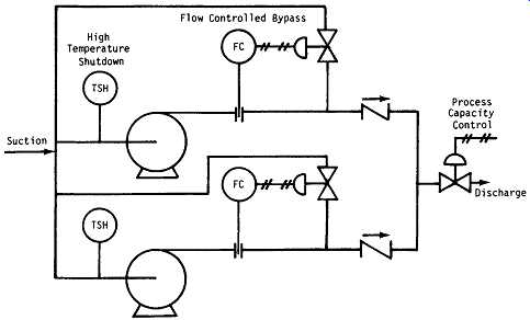
FIG.47 Parallel pumps with individually controlled recycle lines. (Sundstrand
Fluid Handling, Arvada, CO.)
Maintenance Considerations
Routine maintenance on high-speed centrifugal pumps consists of two activities" periodic inspection and periodic service.
Periodic Inspection
The items checked and the frequency of checking will vary with the specific design of the pump and its duty. The common ingredient in high-speed pumps is the integral speed-increasing gear box. Lube oil level, lube pressure, and temperature are normal inspection items on all of these pumps, requiring monitoring at least once per week.
The need for periodic inspections will vary with the type of auxiliary equipment installed on the pump.
Where there are additional auxiliary systems supporting the pump, there are normally automatic alarm and shutdown devices that help to simplify inspection tasks. Proper functioning of protective alarm and shutdown devices should be verified periodically. If such tests are to be made while the equipment is running, it’s best to specify this provision when pump and auxiliary equipment are initially purchased.
It’s best if the periodic inspections include record keeping. Records can show trends that can help in the planning of service work, keeping maintenance costs low.
Periodic Service
Lubrication requirements are normally identified in the manufacturer's instruction manual. The driver, coupling, and gearbox each have their own lubrication needs.
Each machine is designed to be run using lubricants with certain specific properties, so the manufacturer's recommendation should be considered when lubricants are chosen. Dibasic ester and poly-alpha olefin synthetic lubes are often advantageous.
Many high-speed gear pumps incorporate a modular high-speed rotor assembly that is easily removed for inspection and maintenance.
Contaminants in the pumped fluid or in the bearing lubricant can penetrate through the film that separates the moving and stationary parts, and also may cause wear.
Seal life is primarily determined by the seal environment. Most pumps have features that allow the user to control the seal environment maximum seal life. If seal life of less than six months occurs, then system modifications can often extend the life. If life greater than one or two years is observed, then system modifications to further improve the life won’t likely be cost effective. Overall, seals and bearings are considered wearing items needing periodic maintenance. The frequency of this maintenance can vary significantly with the type of duty the pump serves.
When bearings are replaced on high-speed pumps, the manufacturer's recommendations should be followed. In addition to the load capacity of high-speed ball bearings, internal clearances, contact angle, tolerance class, and retainer design are all important factors. Modem pump manufacturers specify bearings that operate well within the manufacturer's ratings, but careless substitutions can have disastrous results.
Machinery Condition Monitoring. High-speed pumps in critical service are often monitored for continuous determination of machine condition. Parameters most often monitored are vibration, lube pressure and temperature, and bearing temperature.
Such monitoring is not normally considered mandatory by pump manufacturers for general pump service. However, contemporary manufacturers generally can provide optional provisions for monitoring these items when needed for pumps in critical service.
Vibration Monitoring. The three types of vibration monitoring most commonly used are noncontacting proximity probes, seismic casing vibration sensors, and acceleration-spike energy transducers. Noncontacting proximity probes measure shaft displacement (peak-to-peak). These probes are normally installed inside the speed-increasing gearbox to measure displacement of the output shaft relative to the gearbox housing. They are normally installed by the manufacturer and are ordered with the pump at purchase. Casing vibration sensors normally measure housing velocity amplitude. Such instruments can be either permanently installed on the gearbox or can be obtained as portable units that are periodically taken from one machine to another. Acceleration-spike energy monitoring is often done with portable data terminals and is one of the most effective ways to obtain early warning of incipient defects in rolling element beatings. With either permanently mounted or portable types of instruments, it’s best to take readings periodically and to monitor trends. Permanently installed instruments are normally connected to automatic alarm and shutdown controls.
Lube Pressure and Temperature. When pressurized lubrication systems are used on speed-increasing gearboxes, lube oil pressure and temperature are often monitored. If pressures fall or temperatures rise, the equipment can be shut down automatically to prevent or minimize damage.
Bearing Temperature. On pumps with journal bearings, temperature sensors can be imbedded in the bearings. Temperature sensors are usually either thermocouples or resistance temperature detectors (RTDs). Bearing temperature monitoring can provide early warning of loss of lubricating properties, reduction in lubricant flow, bearing failure, or loss of lubricant cooling.
Also see:
http://en.wikipedia.org/wiki/Volute_(pump)
SUB-SECTION 7A
Centrifugal Pump Fundamentals
Head The pressure at any point in a liquid can be thought of as being caused by a vertical column of the liquid which, due to its weight, exerts a pressure equal to the pressure at the point in question. The height of this column is called the "static head" and is expressed in terms of feet of liquid.
The static head corresponding to any specific pressure is dependent upon the weight of the liquid according to the following formula: Pressure in pal x 2.31 Head in Feet = Specific Gravity A Centrifugal pump imparts velocity to a liquid. This velocity energy is then transformed largely into pressure energy as the liquid leaves the pump. Therefore, the head developed is approximately equal to the velocity energy at the periphery of the impeller. This relationship is expressed by the following well known formula: V 2 H-..m 2g Where H = Total head developed in feet.
v = Velocity at periphery of impeller in feet per sec.
g = 32.2 Feet/Sec.^2
We can predict the approximate head of any centrifugal pump by calculating the peripheral velocity of the impeller and substituting into the above formula. A handy formula for peripheral velocity is: RPMxD v = Where D = Impeller diameter in inches.
229 The above demonstrates why we must always think in terms of feet of liquid rather than pressure when working with centrifugal pumps. A given pump with a given impeller diameter and speed will raise a liquid to a certain height regardless of the weight of the liquid, as shown in FIG. A-1.
All of the forms of energy involved in a liquid flow system can be expressed in terms of feet of liquid. The total of these various heads determines the total system head or the work which a pump must perform in the system. The various forms of head are defined as follows.
SUCTION LIFT exists when the source of supply is below the center line of the pump. Thus the STATIC SUCTION LIFT is the vertical distance in feet from the center line of the pump to the free level of the liquid to be pumped.
SUCTION HEAD exists when the source of supply is above the centerline of the pump. Thus the STATIC SUCTION HEAD is the vertical distance in feet from the centerline of the pump to the free level of the liquid to be pumped.
STATIC DISCHARGE HEAD is the vertical distance in feet between the pump centerline and the point of free discharge or the surface of the liquid in the discharge tank.
TOTAL STATIC HEAD is the vertical distance in feet between the free level of the source of supply and the point of free discharge or the free surface of the discharged liquid.
The above forms of static head are shown graphically in FIG. A-2(a) and (b)
FRICTION HEAD (hf) is the head required to overcome the resistance to flow in the pipe and fittings. It’s dependent upon the size and type of pipe, flow rate, and nature of the liquid.
VELOCITY HEAD (hv) is the energy of a liquid as a result of its motion at some velocity V. It’s the equivalent head in feet through which the water would have to fall to acquire the same velocity, or in other words, the head necessary to accelerate the water. Velocity head can be calculated from the following formula: v 2 hv 2-~ where g = 32.2 ft/sec. 2
= v = liquid velocity in feet per second.
The velocity head is usually insignificant and can be ignored in most high head systems. However, it can be a large factor and must be considered in low head systems.
PRESSURE HEAD must be considered when a pumping system either begins or terminates in a tank which is under some pressure other than atmospheric. The pressure in such a tank must first be converted to feet of liquid. A vacuum in the suction tank or a positive pressure in the discharge tank must be added to the system head, whereas a positive pressure in the suction tank or vacuum in the discharge tank would be subtracted. The following is a handy formula for converting inches of mercury vacuum into feet of liquid.
Vacuum, In. of Hg x 1.13 Vacuum, ft. of liquid = Sp. Gr.
The above forms of head, namely static, friction, velocity, and pressure, are combined to make up the total system head at any particular flow rate. Following are definitions of these combined or "Dynamic" head terms as they apply to the pump.
FIG. A-1 Identical pumps handling liquids of different specific gravities
FIG. A-2 (a) Suction lift - showing static heads In a pumping system where the pump is located above the suction tank (static suction head)
TOTAL DYNAMIC SUCTION LIFT (hs) is the static suction lift minus the velocity head at the pump suction flange plus the total friction head in the suction line. The total dynamic suction lift, as determined on pump test, is the reading of a gage on the suction flange, converted to feet of liquid and corrected to the pump centerline*, minus the velocity head at the point of gage attachment.
TOTAL DYNAMIC SUCTION HEAD (hs) is the static suction head plus the velocity head at the pump suction flange minus the total friction head in the suction line. The total dynamic suction head, as determined on pump test, is the reading of the gage on the suction latiange, converted to feet of liquid and corrected to the pump centerline*, plus the velocity head at the point of gage attachment.
TOTAL DYNAMIC DISCHARGE HEAD (hd) is the static discharge head plus the velocity head at the pump discharge flange plus the total friction head in the discharge line. The total dynamic discharge head, as determined on pump test, is the reading of a gage at the discharge flange, converted to feet of liquid and corrected to the pump centerline*, plus the velocity head at the point of gage attachment.
TOTAL HEAD (H) or TOTAL DYNAMIC HEAD (TDH) is the total dynamic discharge head minus the total dynamic suction head or plus the total dynamic suction lift.
TDH = hd + h=(with a suction lift)
TDH = hd - h=(wlth a suction head)
*On vertical pumps the correction should be made to the eye of the suction or lowest impeller.
FIG. A-2 (b) Suction head - showing static heads in a pumping system where the pump is located below the suction tank (static suction head)
Capacity:
Capacity (Q) is normally, expressed in gallons per minute (gpm). Since liquids are essentially incompressible, there is a direct relationship between the capacity in a pipe and the velocity of flow. This relationship is as follows: Where Q Q=AxVorV= -- A A = Area of pipe or conduit in square feet.
V = Velocity of flow in feet per second.
The constant 3960 is obtained by dividing the number or foot pounds for one horsepower (33,000) by the weight of one gallon of water (8.33 pounds.) The brake horsepower or input to a pump is greater than the hydraulic horsepower or output due to the mechanical and hydraulic losses incurred in the pump. Therefore the pump efficiency is the ratio of these two values.
Pump Eft - whp _ Q x TDH x Sp. Gr.
bhp 3960 x bhp
Power and Efficiency
The work performed by a pump is a function of the total head and the weight of the liquid pumped in a given time period.
The pump capacity in gpm and the liquid specific gravity are normally used in the formulas rather than the actual weight of the liquid pumped.
Pump input or brake horsepower (bhp) is the actual horse- power delivered to the pump shaft. Pump output or hydraulic horsepower (whp) is the liquid horsepower delivered by the pump. These two terms are defined by the following formulas.
Q x TDH x Sp. Gr.
whp = 3960
Specific Speed and Pump Type
Specific speed (Ns) is a non-dimensional design index used to classify pump impellers as to their type and proportions. It’s defined as the speed in revolutions per minute at which a geometrically similar impeller would operate if it were of such a size as to deliver one gallon per minute against one foot head.
The understanding of this definition is of design engineering significance only, however, and specific speed should be thought of only as an index used to predict certain pump characteristics. The following formula is used to determine specific speed:
FIG. A-3 Impeller design vs specific speed
Where N = Pump speed in RPM Q = Capacity in gpm at the best efficiency point H = Total head per stage at the best efficiency point The specific speed determines the general shape or class of the impeller as depicted in FIG. A-3. As the specific speed increases, the ratio of the impeller outlet diameter, D2, to the inlet or eye diameter, D1, decreases. This ratio becomes 1.0 for a true axial flow impeller.
Radial flow impellers develop head principally through centrifugal force. Pumps of higher specific speeds develop head partly by centrifugal force and partly by axial force. A higher specific speed indicates a pump design with head generation more by axial forces and less by centrifugal forces. An axial flow or propeller pump with a specific speed of 10,000 or greater generates its head exclusively through axial forces.
Radial impellers are generally low flow high head designs where as axial flow impellers are high flow low head designs.
Net Positive Suction Head (NPSH) and Cavitation
The Hydraulic Institute defines NPSH as the total suction head in feet absolute, determined at the suction nozzle and corrected to datum, less the vapor pressure of the liquid in feet absolute. Simply stated, it’s an analysis of energy conditions on the suction side of a pump to determine if the liquid will vaporize at the lowest pressure point in the pump.
The pressure which a liquid exerts on its surroundings is dependent upon its temperature. This pressure, called vapor pressure, is a unique characteristic of every fluid and increases with increasing temperature. When the vapor pressure within the fluid reaches the pressure of the surrounding medium, the fluid begins to vaporize or boil. The temperature at which this vaporization occurs will decrease as the pressure of the surrounding medium decreases.
A liquid increases greatly in volume when it vaporizes. One cubic foot of water at room temperature becomes 1700 cu. ft. of vapor at the same temperature.
===
Pe == Barometric pressure, in feet absolute.
Vp == Vapor pressure of the liquid at maximum pumping temperature, in feet absolute.
P == Pressure on surface of liquid in closed suction tank, in feet absolute.
L= == Maximum static suction lift in feet.
LH --" Minimum static suction head in feet.
ht = Friction loss in feet in suction pipe at required capacity
FIG. A-4 Calculation of system net positive suction head available for typical suction conditions
===
It’s obvious from the above that if we are to pump a fluid effectively, we must keep it in liquid form. NPSH is simply a measure of the amount of suction head present to prevent this vaporization at the lowest pressure point in the pump.
NPSH Required is a function of the pump design. As the liquid passes from the pump suction to the eye of the impeller, the velocity increases and the pressure decreases. There are also pressure losses due to shock and turbulence as the liquid strikes the impeller. The centrifugal force of the impeller vanes further increases the velocity and decreases the pressure of the liquid. The NPSH Required is the positive head in feet absolute required at the pump suction to overcome these pressure drops in the pump and maintain the liquid above its vapor pressure. The NPSH Required varies with speed and capacity within any particular pump. Pump manufacturer's curves normally provide this information.
NPSH Available is a function of the system in which the pump operates. It’s the excess pressure of the liquid in feet absolute over its vapor pressure as it arrives at the pump suction.
FIG. A-4 shows four typical suction systems with the NPSH Available formulas applicable to each. It’s important to correct for the specific gravity of the liquid and to convert all terms to units of fleet absolute" in using the formulas.
In an existing system, the NPSH Available can be determined by a gage reading on the pump suction. The following formula applies:
NPSHA = Ps - Vp + Gr + hv
Where Gr = Gage reading at the pump suction expressed in feet (plus if above atmospheric, minus if below atmospheric) corrected to the pump centerline.
hv = Velocity head in the suction pipe at the gage connection, expressed in feet.
Cavitation is a term used to describe the phenomenon which occurs in a pump when there is insufficient NPSH Available.
The pressure of the liquid is reduced to a value equal to or below its vapor pressure and small vapor bubbles or pockets begin to form. As these vapor bubbles move along the impeller vanes to a higher pressure area, they rapidly collapse.
The collapse, or "implosion" is so rapid that it may be heard as a rumbling noise, as if you were pumping gravel. The forces during the collapse are generally high enough to cause minute pockets of fatigue failure on the impeller vane surfaces. This action may be progressive, and under severe conditions can cause serious pitting damage to the impeller.
The accompanying noise is the easiest way to recognize cavitation. Besides impeller damage, cavitation normally results in reduced capacity due to the vapor present in the pump. Also, the head may be reduced and unstable and the power consumption may be erratic. Vibration and mechanical damage such as bearing failure can also occur as a result of operating in cavitation.
The only way to prevent the undesirable effects of cavitation is to insure that the NPSH Available in the system is greater than the NPSH Required by the pump.
===
Pe == Barometric pressure, in feet absolute.
Vp == Vapor pressure of the liquid at maximum pumping temperature, in feet absolute.
P == Pressure on surface of liquid in closed suction tank, in feet absolute.
L= == Maximum static suction lift in feet.
LH --" Minimum static suction head in feet.
ht = Friction loss in feet in suction pipe at required capacity FIG. A-4 Calculation of system net positive suction head available for typical suction conditions
===
FIG. A-5 Radial flow pump
FIG. A-6 Mixed flow pump
FIG. A-7 Axial flow pump
Pump Characteristic Curves
The performance of a centrifugal pump can be shown graphically on a characteristic curve. A typical characteristic curve shows the total dynamic head, brake horsepower, efficiency, and net positive suction head all plotted over the capacity range of the pump.
FIGs. A-5, 6, & 7 are non-dimensional curves which indicate the general shape of the characteristic curves for the various types of pumps. They show the head, brake home- power, and efficiency plotted as a per cent of their values at the design or best efficiency point of the pump.
FIG. A-5 shows that the head curve for a radial flow pump is relatively flat and that the head decreases gradually as the flow increases. Note that the brake horsepower increases gradually over the flow range with the maximum normally at the point of maximum flow.
Mixed flow centrifugal pumps and axial flow or propeller pumps have considerably different characteristics as shown in FIGs. A-6 and 7. The head curve for a mixed flow pump is steeper than for a radial flow pump. The shut-off head is usually 150% to 200% of the design head. The brake home- power remains fairly constant over the flow range. For a typical axial flow pump, the head and brake horsepower both increase drastically near shut-off as shown in FIG. A-7.
The distinction between the above three classes is not absolute, and there are many pumps with characteristics falling somewhere between the three. For instance, the Francis vane impeller would have a characteristic between the radial and mixed flow classes. Most turbine pumps are also in this same range depending upon their specific speeds.
FIG. A-8 shows a typical pump curve as furnished by a manufacturer. It’s a composite curve which tells at a glance what the pump will do at a given speed with various impeller diameter from maximum t_Q minimum __Constant .... horsepower, efficiency, and NPSHR lines are superimposed
over the various head curves. It’s made up from individual test curves at various diameters.
FIG. A-8 Composite performance curve
Affinity Laws
The affinity laws express the mathematical relationship between the several variables involved in pump performance.
They apply to all types of centrifugal and axial flow pumps.
They are as follows:
1. With impeller diameter, D, held constant:
2. With speed, N, held constant:
When the performance (Q1, H1, & BHP1) is known at some particular speed (N1) or diameter (D1), the formulas can be used to estimate the performance (Q2, H2, & BHP2) at some other speed (N2) or diameter (D2). The efficiency remains nearly constant for speed changes and for small changes in impeller diameter.
EXAMPLE
To illustrate the use of these laws, refer to FIG. A-8. It shows the performance of a particular pump at 1750 rpm with
plotting the system head curve and pump curve together, we can tell:
1. Where the pump will operate on its curve.
2. What changes will occur if the system head curve or the pump performance curve changes.
STATIC SYSTEM HEAD
Consider the system shown in FIG. A-10. Since the lines are oversized and relatively short, the friction head is small compared to the static head. For this example, the system head will be considered as entirely static, with the friction neglected.
Assume the fluid being handled has 1.0 Sp. Gr. NPSHA is 13'. The flow requirement is 100 gpm. Since the system head is made up entirely of elevation and pressure differences, it does not vary with flow.
The normal system head is 250' TDH (19' elevation difference plus 231' pressure difference). Since the discharge vessel pressure may vary +3 psi, the system head will vary between 243' and 257'. Consider the application of a pump sized for 100 gpm at 250' TDH, with a relatively flat performance curve as shown in Fig. 11. Note that the pump will shut off at 254' TDH. At the maximum discharge tank pressure, the pump will stop delivering fluid, as the system head is greater than the pump TDH. A second consideration associated with static system head is motor overload on pump runout. Again, consider FIG. A-11 at the minimum system head of 243'. The pump under discussion will deliver 130 gpm against 243' head. Home- power requirements will increase from 8.9 BHP at 100 gpm to 12.0 BHP at 130 gpm. A 10 HP motor could be overloaded on this service.
NPSH problems may also arise when large increases in flow occur. At the rating of 100 gpm at 250' TDH the NPSHR of the pump is only 10' while the system NPSHA is 13'. At the lower system head of 243' the pump requires 13.5' NPSH and cavitation will probably occur.
A better selection would be a pump with a characteristic as shown in FIG. A-12. The steeper characteristic will limit the flow to between 90 GPM at 257' TDH and 110 gpm at 243' TDH. The small increase in capacity at low head condition will mean no motor overload. Since the maximum flow is 110 gpm, the maximum NPSHR will be 12' and the pump won’t cavitate.
DYNAMIC SYSTEM HEAD
In frictional systems where resistance to flow increases with flow, the system head characteristic becomes curved. The magnitude of the system head at each flow is the summation of the system static head plus the total friction losses at that particular flow rate. A typical example of this type of system is shown in FIG. A-13.
Unlike the static system, the friction system is always self- correcting to some degree. Consider the above system with a flow requirement of 6000 gpm at 150' TDH. Also assume that the discharge tank level may drop 10'. The new system head curve will be parallel to the original one, but 10' lower as shown in FIG. A-14. Flow under this reduced head will be 6600 gpm at 144' rather than the normal 6000 gpm at 150'. This increased flow rate will tend to raise the discharge tank level back to normal.
The frictional resistance of pipes and fittings will increase as they wear, resulting in greater curvature of the system head curve. A slight drop in the pump head curve may also result from increasing pump wear and recirculation. These changes will have less effect on the flow in a dynamic system (steep curve) than in a static system (flat curve). PARALLEL OPERATION
It’s sometimes desirable to use two or more pumps in parallel rather than a single larger pump. This is particularly advantageous when the system flow requirements vary greatly.
One pump can be shut down when the flow requirement drops, allowing the remaining pump or pumps to operate closer to their peak efficiency. It also provides an opportunity for repairs or maintenance work on one unit without shutting down the entire system.
Special care must be taken in selecting pumps for parallel operation. Consideration must be given to single pump operation in the system as well as parallel operation. Consider the system shown in FIG. A-15. The NPSH available is plotted along with the system head. Since entrance and line losses increase with increases in flow, the NPSHA decreases with flow increases.
The flow required is 16,000 gpm. We want to use two pumps in parallel, but each must be capable of single operation.
The total system head at 16,000 gpm is 140'. Each pump must be sized for 8000 gpm at 140' TDH. NPSHR for each pump must be less than 28' for parallel operation. Consider applying two pumps each with characteristics as shown in FIG. A-16. In order to study both parallel and single pump operation, the head-capacity curves for both single and parallel operation must be plotted with the system head curve.
The head-capacity pump curve for parallel operation is plotted by adding the capacities of each pump for several different heads and plotting the new capacity at each head. The shut- off head for the two pumps in parallel is the same as for single operation. The NPSH curve is plotted in the same manner as shown in FIG. A-16. For example, the NPSHR for one pump at 8000 gpm is 14'. Therefore, in parallel operation 16,000 gpm can be pumped with 14' NPSHR by each pump.
The curve show that each pump will deliver 8000 gpm at 140' TDH when operating in parallel. Brake horsepower for each unit will be 340 HP. NPSHR is 14'. NPSHA is 28'. With only one pump operating, the flow will be 11,000 gpm at 108' TDH. BHP will be 355 HP. NPSHR is 26' and NPSHA is 30'. A 400 HP motor would be required.
This example shows that if a 350 HP motor had been selected based on parallel operation only, the motor would have
been overloaded in single pump operation. The single pump operation is also critical in terms of NPSH. For example, if the system NPSHA had been in the neighborhood of 20', parallel pump operation would have been fine, but single pump operation would result in cavitation.
Basic Formulae and Symbols
Pump Application Data Corrosion and Materials of Construction
Corrosion is the destructive attack of a metal by chemical or electro-chemical reaction with its environment. It’s important to understand the various types of corrosion and factors affecting corrosion rate to properly select materials.
Types of Corrosion
(1) Galvanic corrosion is the electro-chemical action produced when one metal is in electrical contact with another more noble metal, with both being immersed in the same corroding medium called the electrolyte. A galvanic cell is formed and current flows between the two materials. The least noble material called the anode will corrode while the more noble cathode will be protected. It’s important that the smaller wearing parts in a pump be of a more noble material than the larger more massive parts, as in an iron pump with bronze or stainless steel trim.
Following is a galvanic series listing the more common metals and alloys:
Corroded End (Anodic, or Nickel base alloy (active)
least noble) Brasses
. SYMBOLS
GPM = gallons per minute Lb. = pounds Hr. = hour Sp. Gr. = specific gravity H = head in feet psi = pounds per square inch In. Hg. = Inches of mercury hv = velocity head in feet V = velocity in feet per second g = 32.16 ft/sec 2 (acceleration of gravity)
A = area in square inches I.D. = Inside diameter in inches BHP = brake horsepower Eft. = pump efficiency expressed as a decimal Ns = specific speed N = speed in revolutions per minute v = peripheral velocity of an impeller in feet per second D = Impeller in inches
Magnesium Copper Magnesium Alloys Bronzes Zinc Copper-Nickel Alloy Aluminum 2S Monel Cadmium Silver Solder Aluminum 17ST Nickel (Passive)
Steel or Iron Nickel Base Alloy (Passive)
Cast Iron Stainless Steel, 400 Series Stainless Steel, 400 Series (Passive)
(Active) Stainless Steel, Type 304 Stainless Steel, Type 304 (Passive)
(Active) Stainless Steel, Type 316 Stainless Steel, Type 316 (Passive)
(Active) Silver Lead-tin Solders Graphite Lead Gold Tin Platinum Nickel (Active) Protected End (Cathodic, or most noble)
(2) Uniform Corrosion is the overall attack on a metal by a corroding liquid resulting in a relatively uniform metal loss over the exposed surface. This is the most common type of corrosion and it can be minimized by the selection of a material which offers resistance to the corroding liquid.
(3) Inter-granular corrosion is the precipitation of chromium carbides at the grain boundaries of stainless steels. It results in the complete destruction of the mechanical properties of the steel for the depth of the attack. Solution annealing or the use of extra low carbon stainless steels will eliminate inter-granular corrosion.
(4) Pitting Corrosion is a localized rather than uniform type of attack. It’s caused by a breakdown of the protective film and results in rapid pit formation at random locations on the surface.
(5) Crevice or Concentration Cell Corrosion occurs in joints or small surface imperfections. Portions of the liquid become trapped and a difference in potential is established due to the oxygen concentration difference in these cells.
The resulting corrosion may progress rapidly leaving the surrounding area unaffected.
(6) Stress Corrosion is the failure of a material due to a combination of stress and a corrosive environment, whereas the material would not be affected by the environment alone.
(7) Erosion-Corrosion is the corrosion resulting when a metal's protective film is destroyed by high velocity fluids.
It’s distinguished from abrasion which is destruction by fluids containing abrasive solid particles.
pH Values
The pH of a liquid is an indication of its corrosive qualities, either acidic or alkaline. It’s a measure of the hydrogen or hydroxide ion concentration in gram equivalents per liter, pH value is expressed as the logarithm to the base 10 of the reciprocal of the hydrogen ion concentration. The scale of pH values is from zero to 14, with 7 as a neutral point. From 6 to zero denotes increasing hydrogen ion concentration and thus increasing acidity; and from 8 to 14 denotes increasing hydroxide ion concentration and thus increasing alkalinity.
The table below outlines materials of construction usually recommended for pumps handling liquids of known pH value.
pH Value Material of Construction
10 to 14 Corrosion Resistant Alloys 8 to 10 All Iron 6 to 8 Bronze fitted or Standard fitted 4 to 6 All Bronze
0 to 4 Corrosion Resistant Alloy Steels
The pH value should only be used as a guide with weak aqueous solutions. For more corrosive solutions, temperature and chemical composition should be carefully evaluated in the selection of materials of construction.
Materials Selection Chart
This chart is intended as a guide in the selection of economical materials. It must be kept in mind that corrosion rates may vary widely with temperature, concentration, and the presence of trace elements or abrasive solids. Blank spaces indicate a lack of accurate corrosion information for those specific conditions.
C.I-Cast Iron, ASTM A48.
D.I-Ductile Iron, ASTM A536.
Steel-Carbon Steel, ASTM A216-WCA or WCB. Brz-Anti-Acid Bronze, Similar to ASTM B143A2.
316SS-Stainless Steel, ASTM A744 Gr. CF-8M, AISI 316.
GA-20-Carpenter Stainless No.20, ASTM A744 Gr. CN-7M. CD4MCu-Stainless Steel, ACI CD-4MCu.
Mon-Monel Grade E. ASTM A744 Gr. M-35.
NI-Nickel, ASTM A744 Gr.CZ-100. H-B-Hastelloy Alloy-B, ASTM A494.
H-C-Hastelloy Alloy-C, ASTM A494.
TI-Titanium Unalloyed, ASTM B367 Gr. C-1.
ZI-Zirconium Code
A- Fully Satisfactory. C - Limited Use.
B - Useful Resistance. X - Unsuitable.
FIG. A-17 Air pockets in suction piping
Piping Design
The design of a piping system can have an important effect on the successful operation of a centrifugal pump. Such items as sump design, suction piping design, suction and discharge pipe size, and pipe supports must all be carefully considered.
Selection of the discharge pipe size is primarily a matter of economics. The cost of the various pipe sizes must be com- pared to the pump size and power cost required to overcome the resulting friction head.
The suction piping size and design is far more important.
Many centrifugal pump troubles are caused by poor suction conditions.
The suction pipe should never be smaller than the suction connection of the pump, and in most cases should be at least one size larger. Suction pipes should be as short and as straight as possible. Suction pipe velocities should be in the 5 to 8 feet per second range unless suction conditions are unusually good.
Higher velocities will increase the friction loss and can result in troublesome air or vapor separation. This is further complicated when elbows or tees are located adjacent to the pump suction nozzle, in that uneven flow patterns or vapor separation keeps the liquid from evenly filling the impeller.
This upsets hydraulic balance leading to vibration, possible cavitation, and excessive shaft deflection. Shaft breakage or premature bearing failure may result.
On pump installations involving suction lift, air pockets in the suction line can be a source of trouble. The suction pipe should be exactly horizontal, or with a uniform slope upward from the sump to the pump as shown in FIG. A-17. There should be no high spots where air can collect and cause the pump to lose its prime. Eccentric rather than concentric reducers should always be used.
If an elbow is required at the suction of a double suction pump, it should be in a vertical position if at all possible. Where it’s necessary for some reason to use a horizontal elbow, it should be a long radius elbow and there should be a minimum of two diameters of straight pipe between the elbow and the pump as shown in FIG. A-18. FIG. A-19 shows the effect of an elbow directly on the suction. The liquid will flow toward the outside of the elbow and result in an uneven flow distribution into the two inlets of the double suction impeller. Noise and excessive axial thrust will result.
There are several important considerations in the design of a suction supply tank or sump. It’s imperative that the amount of turbulence and entrained air be kept to a minimum.
Entrained air will cause reduced capacity and efficiency as well as vibration, noise, shaft breakage, loss of prime, and/or accelerated corrosion.
The free discharge of liquid above the surface of the supply tank at or near the pump suction can cause entrained air to enter the pump. All lines should be submerged in the tank, and baffles should be used in extreme cases as shown in FIG. A-20. Improper submergence of the pump suction line can cause a vortex which is a swirling funnel of air from the surface directly into the pump suction pipe. In addition to submergence, the location of the pipe in the sump and the actual dimensions of the sump are also important in preventing vortexing and/or excess turbulence.
For horizontal pumps, FIG. A-21 can be used as a guide for minimum submergence and sump dimensions for flows up to approximately 3000 gpm. Baffles can be used to help prevent vortexing in cases where it’s impractical or impossible to maintain the required submergence. FIG. A-22 shows three such baffling arrangements.
FIG. A-18 Elbows at pump suction
FIG. A-19 Effect of elbow directly on suction
FIG. A-20 Keeping air out of pump
Fig.7A-21 Minimum suction pipe submergence and sump dimensions
FIG. A-22 Baffle arrangements for vortex prevention
FIG. A-23 Piping arrangements within multiple pump pits
FIG. A-24 Typical stuffing box arrangement (description of parts)
FIG. A-25 Typical stuffing box arrangement when stuffing box pressure is above atmosphere pressure
FIG. A-26 Typical stuffing box arrangement when stuffing box pressure is below atmospheric pressure
FIG. A-27 Typical stuffing box arrangement when pumping slurries.
Large units (over 3000 gpm) taking their suction supply from sumps, especially vertical submerged pumps, require special attention. The larger the unit, the more important the sump design becomes.
be located near the back wall and should not be subjected to rapid changes in direction of the flow pattern. The velocity of the water in the area of the suction pipes should be kept below one foot per second to avoid air being drawn into the pump.
FIG. A-23 illustrates several preferred piping arrangements within a multiple pump pit. Note that the pipe should always On horizontal pumps, a bell should be used on the end of the suction pipe to limit the entrance velocity to 3.5 feet per second. Also, a reducer at the pump suction flange to smoothly accelerate and stabilize the flow into the pump is desirable.
The submergence of the suction pipe must also be carefully considered. The amount of submergence required depends upon the size and capacity of the individual pumps as well as on the sump design. Past experience is the best guide for determining the submergence. The pump manufacturer should be consulted for recommendations in the absence of other reliable data.
Stuffing Box Sealing
The stuffing box of a pump provides an area in which to seal against leakage out of the pump along the shaft. Packing and mechanical seals are the two devices used to accomplish this seal.
Packing
A typical packed stuffing box arrangement is shown in FIG. A-24. It consists of: A)Five rings of packing. B)A lantern ring used for the injection of a lubricating and/or flushing liquid, and C)A gland to hold the packing and maintain the desired compression for a proper seal.
The function of packing is to control leakage and not to eliminate it completely. The packing must be lubricated, and a flow of from 40 to 60 drops per minute out of the stuffing box must be maintained for proper lubrication.
When pumping slurries or abrasive liquids, it’s necessary to inject a clean lubricating liquid from an external source into the lantern ring ( FIG. A-27). A flow of from .2 to .5 gpm is desirable and a valve and flowmeter should be used for accurate control. The seal water pressure should be from 10 to 15 psi above the stuffing box pressure, and anything above this will only add to packing wear. The lantern ring is normally located in the center of the stuffing box. However, for extremely thick slurries like paper stock, it’s recommended that the lantern ring be located at the stuffing box throat to prevent stock from contaminating the packing.
The gland shown in FIGs. A-24 to 27 is a quench type gland. Water, oil, or other fluids can be injected into the gland to remove heat from the shaft, thus limiting heat transfer to the bearing frame. This permits the operating temperature of the pump to be higher than the limits of the bearing and lubricant design. The same quench gland can be used to prevent the escape of a toxic or volatile liquid into the air around the pump.
This is called a smothering gland, with an external liquid simply flushing away the undesirable leakage to a sewer or waste receiver.
FIG. A-28 Basic mechanical seal
FIG. A-29 Single, Inside, unbalanced seal
FIG. A-31 Single, Inside, balanced seal
FIG. A-30 Single, outside, unbalanced seal
FIG. A-32 Double, inside, unbalanced seal
FIG. A-33 Tandem, Inside unbalanced seals
Mechanical Seals
The Basic Seal
A mechanical seal is a sealing device which forms a running seal between rotating and stationary parts. The design of liquid handling equipment with rotating parts today would include the consideration for the use of mechanical seals. Advantages over conventional packing are as follows:
1. Reduced friction and power losses.
2. Zero or limited leakage of product.
3. Elimination of shaft or sleeve wear.
4. Reduced maintenance.
5. Ability to seal higher pressures and more corrosive environments.
The wide variety of styles and designs together with extensive experience allows the use of seals on most pump applications.
A mechanical seal must seal at three points:
1. Static seal between the stationary part and the housing.
2. Static seal between the rotary part and the shaft.
3. Dynamic seal between the rotating seal face and the stationary seal face.
FIG. A-28 shows a basic seal with these components:
1. Stationary seal part positioned in the housing with preload on the "O" ring to effect sealing and prevent rotation.
2. Rotating seal part positioned on the shaft by the "O" ring.
The "O" ring seals between it and the shaft and provides resiliency.
3. The mating faces. The faces are precision lapped for a flatness of 3 light bands and a surface finish of 5 micro-inches.
4. Spring assembly, rotates with the shaft and provides pres- sure to keep the mating faces together during periods of shut down or lack of hydraulic pressure.
5. Driving member, positions the spring assembly and the rotating face. It also provides the positive drive between shaft and the other rotating parts.
As wear takes place between the mating faces, the rotating face must move along the shaft to maintain contact with stationary face. The "O" ring must be free to move.
A mechanical seal operates as each basic component per- forms its duty. Liquid pressure in the seal chamber forces the faces together and provides a thin film of lubricant between them. The faces, selected for low frictional qualities, are the only rubbing parts. These basic components are a part of every seal. The form, shape, style and design will vary greatly depending on service and manufacture. The basic theory, however, remains the same.
Types
Mechanical seals can be classified into the general types and arrangements shown below. Understanding these classes provides the first step in proper seal selection.
(a) Single seals-Inside, outside, unbalanced, balanced (b) Double seals- Unbalanced or balanced Single Seal, Inside Unbalanced The single inside seal mounts on the shaft or sleeve within the stuffing box housing. The pumpage is in direct contact with all parts of the seal and provides the lubrication for the faces. The full force of pressure in the box acts on the faces providing good sealing to approximately 100 P.S.I.G. This is the most widely used type for services handling clear liquids.
A circulation or by-pass line connected from the volute to the stuffing box provides continual flushing of the seal chamber.
Single Seals, Outside Unbalanced
This type mounts with the rotary part outside of the stuffing box. The springs and drive element are not in contact with the pumpage, thus reducing corrosion problems and preventing product accumulation in the springs. Pressures are limited to the spring rating, usually 35 P.S.I.G. Usually the same style seal can be mounted inside or outside. The outside seal is easier to install, adjust and maintain. A restricting bushing can be used to control leakage of an external sealing liquid into the pumpage.
Single Seals, Balanced
Balancing a seal varies the face loading exerted by the box pressure, thus extending the pressure limits of the seal. A balanced rotating part utilizes a stepped face and a sleeve.
Balanced seals are used to pressures of 2000 P.S.I.G. Their use is also extensive on light hydrocarbons which tend to vaporize easily.
Balanced outside seals allow box pressure to be exerted toward the seal faces, thus allowing pressure ranges to above 150 P.S.I. as compared to the 35 P.S.I.G. limit for the unbalanced outside seal.
Double Seals
Double seals use two seals mounted back to in the stuffing box. The stuffing box is pressurized with a clear liquid from an external source. This liquid is circulated thru the double seal chamber at 1/4-1 GPM to cool and lubricate the mechanical seals. Double seals are used on solutions that contain solids, are toxic or extremely corrosive. The external source fluid should be compatible with the pumpage.
FIG. A-34 Pressure-velocity limits, unbalanced seals -- Maximum stuffing box pressures for Unbalanced Mechanical Seals on water solutions 160" max. Unbalanced seals generally limited to 200 PSIG maximum stuffing box pressure. All ratings based on one carbon face against hard face:
TANDEM SEALS
A variation of the double seal arrangement. The purpose of this seal is to provide a backup seal in the event the primary seal fails. The primary mechanical seal functions in a manner identical to that of a conventional single inside seal. The cavity between the primary seal and the backup seal is flooded with liquid to provide lubrication for the backup seal. The seal arrangement is used on toxic or hazardous chemical, and transfer and pipeline services to provide an extra measure of safety and allow equipment to operate until time to shut down.
Selection The proper selection of a mechanical seal can be made only if the full operating conditions are known. These conditions are as follows:
1. Liquid
2. Pressure
3. Temperature
4. Characteristics of Liquid
1. Liquid Identification of the exact liquid to be handled pro- vides the first step in seal selection. The metal parts must be corrosion resistant. These pads, usually available in steel, bronze, stainless steel, or Hastelloy, provide a wide choice to meet specific services.
The mating faces must also resist both corrosion and wear Carbon, ceramic glass-filled Teflon, Stellite or tungsten car- bide are available and offer both excellent wear properties and corrosion resistance.
Stationary sealing members of synthetic rubber, asbestos and Teflon complete the proper material selection.
2. Pressure The proper type of seal, unbalanced or balanced, is based on the pressure on the seal and on the seal size.
FIG. A-34 shows the normal limits for unbalanced seals of various types.
3. Temperatures The temperature will in part determine the use of the sealing members Synthetic rubbers are used to approximately 400 F., Teflon to 500 F. and asbestos to 750 F. Cooling the liquid in the seal chamber by water cooling jackets or cool liquid flushing, often extends seal life and allows wider selection of materials.
4. Characteristics of Liquid Abrasive liquids create excessive wear and short seal life. Double seals or clear liquid flushing from an external source allows the use of mechanical seals on these difficult liquids. On light hydrocarbons balanced seals are often used to promote longer seal life, even though pressures are low.
Environmental Controls Environmental controls are necessary for reliable performance of a mechanical seal on many applications. Pump manufactures and the seal vendors offer a variety of arrangements to combat these problems.
1. Corrosion
2. Temperature Control
3. Dirty or incompatible environments
FIG. A-37 Determination of total head from gauge readings
CORROSION
Corrosion can be controlled by selecting seal materials that are not attacked by the pumpage. When this is difficult, external fluid injection of a non-corrosive chemical to lubricate the seal is possible. Single or double seals could be used, depending on if the customer can stand delusion of his product.
TEMPERATURE CONTROL
As the seal rotates, the faces are in contact. This generates heat and if this heat is not removed, the temperature in the stuffing box can increase and cause sealing problems. A simple by-pass flush of the product over the seal faces will remove the heat generated by the seal ( FIG. A-35). For higher temperature services, by-pass of product through a cooler may be required to cool the seal sufficiently ( FIG. A-36). External cooling fluid injection can also be used.
Jacketed stuffing boxes are used on many pumps to cool the environment around the mechanical seal ( FIG. A-29). This will also allow the use of a mechanical seal on services where it would not normally function (hot heat transfer oil). For other services, heat is provided to the jacket to melt or prevent the liquid from freezing (liquid sulfur).
DIRTY or INCOMPATIBLE ENVIRONMENTS
Mechanical seals don’t normally function well on liquids which contain solids or can solidify on contact with the atmosphere.
Here, by-pass flush through a filter, a cyclone separator or a strainer are methods of providing a clean fluid to lubricate the stuffing box.
Strainers are effective for particles larger than the openings on a 40 mesh screen.
Cyclone separators are effective on solids 10 micron or more in diameter, if they have a specific gravity of 2.7 and the pump develops a differential pressure of 30-40 psi. Filters are available to remove solids 2 micron and larger.
If external flush with clean liquid is available, this is the most fail proof system. Lip seal or restricting bushings are available to control flow of injected fluid to flows as low as 1/2 GPM ( FIG. A-30).
Quench type glands are used on fluids which tend to crystalize on exposure to air. Water or steam is put through this gland to wash away any build up. Other systems are available as required by the service.
Field Testing Methods
A. Determination of total head
The total head of a pump can be determined by gauge readings as illustrated in FIG. A-37.
Negative Suction Pressure:
TDH = Discharge gauge reading converted to feet of liquid + vacuum gauge reading converted to feet of liquid + distance between point of attachment of vacuum gauge and the centerline of the discharge gauges, h, Vd2 Vs2 I in feet + 2g 2g
Positive Suction Pressure: or TDH = Discharge gauge reading converted to feet of liquid-pressure gauge reading in suction line converted to ft. of liquid + distance between center of discharge and suction gauges, h, in feet+ ( V~ Vs 2 2g 2g )
In using gauges when the pressure is positive or above atmospheric pressure, any air in the gauge line should be vented off by loosening the gauge until liquid appears. This assures that the entire gauge line is filled with liquid and thus the gauge will read the pressure at the elevation of the centerline of the gauge. However, the gauge line will be empty of liquid when measuring vacuum and the gauge will read the vacuum at the elevation of the point of attachment of the gauge line to the pipe line. These assumptions are reflected in the above definitions.
The final term in the above definitions accounts for a difference in size between the suction and discharge lines. The discharge line is normally smaller than the suction line and thus the discharge velocity is higher. A higher velocity results in a lower pressure since the sum of the pressure head and velocity head in any flowing liquid remains constant. Thus, when the suction and discharge line sizes at the gauge attachment points are different, the resulting difference in velocity head must be included in the total head calculation.
Manometers can also be used to measure pressure. The liquid used in a manometer is normally water or mercury, but any liquid of known specific gravity can be used. Manometers are extremely accurate for determining low pressures or vacuums and no calibration is needed. They are also easily fabricated in the field to suit any particular application. FIG. A-38 and 39 illustrate typical manometer set ups.
B. Measurement of capacity a.) Magnetic Flow Meter A calibrated magnetic flow meter is an accurate means of measuring flow in a pumping system. However, due to the expense involved, magnetic flow meters are only practical in small factory test loops and in certain process pumping systems where flow is critical.
b.) Volumetric measurement
Pump capacity can be determined by weighing the liquid pumped or measuring its volume in a calibrated vessel. This is often practical when pumping into an accurately measured reservoir or tank, or when it’s possible to use small containers which can be accurately weighed. These methods, however, are normally suited only to relatively small capacity systems.
c.) Venturi meter: A venturi meter consists of a converging section, a short constricting throat section and then a diverging section. The object is to accelerate the fluid and temporarily lower its static pres- sure. The flow is then a function of the pressure differential between the full diameter line and the throat. FIG. A-40 shows the general shape and flow equation. The meter coefficient is determined by actual calibration by the manufacturer and when properly installed the Venturi meter is accurate to within plus or minus 1%.
===
FIG. A-38 Manometer Indicating vacuum
FIG. A-39 Manometer Indicating pressure
FIG. A-40 Venturi meter
===
d.) Nozzle A nozzle is simply the converging portion of a venturi tube with the liquid exiting to the atmosphere. Therefore, the same formula can be used with the differential head equal to the gauge reading ahead of the nozzle. FIG. A-41 lists theoretical nozzle discharge flows.
e.) Orifice An orifice is a thin plate containing an opening of specific shape and dimensions. The plate is installed in a pipe and the flow is a function of the pressure upstream of the orifice. There are numerous types of orifices available and their descriptions and applications are covered in the Hydraulic Institute Standards and the ASME Fluid Meters Report. Orifices are not recommended for permanent installations due to the inherent high head loss across the plate.
f.) Weir A weir is particularly well suited to measuring flows in open conduits and can be adapted to extremely large capacity systems. For best accuracy, a weir should be calibrated in place. However, when this is impractical, there are formulas which can be used for the various weir configurations. The
most common types are the rectangular contracted weir and the 90 ~ V-notch weir. These are shown in FIG. A-42 with the applicable flow formulas, g.) Pitot tube A pitot tube measures fluid velocity. A small tube placed in the flow stream gives two pressure readings; one receiving the full impact of the flowing stream reads static head + velocity head, and the other reads the static head only ( FIG. A-43). The difference between the two readings is the velocity head. The velocity and the flow are then determined from the following well known formulas.
V = C~ where C is a coefficient for the meter deter- mined by calibration, and hv = velocity head,
Capacity = Area x Average Velocity
Since the velocity varies across the pipe, it’s necessary to obtain a velocity profile to determine the average velocity. This involves some error, but when properly applied a calibrated pitot tube is within plus or minus 2% accuracy.
Vertical Turbine Pumps Turbine Nomenclature
1. DATUM OR GRADE - The elevation of the surface from which the pump is supported.
2. STATIC LIQUID LEVEL-The vertical distance from grade to the liquid level when no liquid is being drawn from the well or source.
3. DRAWDOWN- The distance between the static liquid level and the liquid level when pumping at required capacity.
4. PUMPING LIQUID LEVEL- The vertical distance from grade to liquid level when pumping at rated capacity.
Pumping liquid level equals static water level plus draw- down.
5. SETTING- The distance from grade to the top of the pump bowl assembly.
===
Oil-Rectangular Weir With Complete End Contractions; Weir H = Head in Feet Above Weir FIG. A-42 Weirs.
Total head Static head Small holes on both sides ~ J ~ of outer tube
FIG. A-43 Pitot tube
===
6. TPL (TOTAL PUMP LENGTH) - The distance from grade to lowest point of pump.
7. RATED PUMP HEAD- Lift below discharge plus head above discharge plus friction losses in discharge line. This is the head for which the customer is responsible and does not include any losses within the pump.
8. COLUMN AND DISCHARGE HEAD FRICTION LOSS - Head loss in the pump due to friction in the column assembly and discharge head. Friction loss is measured in feet and is dependent upon column size, shaft size, setting, and discharge head size. Values given in appropriate charts in Data Section.
9. BOWL HEAD - Total head which the pump bowl assembly will deliver at the rated capacity. This is curve performance.
10. BOWL EFFICIENCY- The efficiency of the bowl unit only. This value is read directly from the performance curve.
11. BOWL HORSEPOWER- The horsepower required by the bowls only to deliver a specified capacity against bowl head.
Bowl Head • Capacity
BOWL HP =
3960 • Bowl Efficiency
12. TOTAL PUMP HEAD-Rated pump head plus column and discharge head loss. Note: This is new or final bowl head.
13. SHAFT FRICTION LOSS- The horsepower required to turn the lineshaft in the bearings. These values are given in appropriate table in Data Section.
14. PUMP BRAKE HORSEPOWER- Sum of bowl horse- power plus shaft loss (and the driver thrust bearing loss under certain conditions). 15. TOTAL PUMP EFFICIENCY (WATER TO WATER) - The efficiency of the complete pump less the driver, with all pump losses taken into account.
Specified Pump Head x Capacity Efficiency =
3960 x Brake Horsepower
16. OVERALL EFFICIENCY (WIRE TO WATER)-The efficiency of the pump and motor complete. Overall efficiency = total pump efficiency x motor efficiency.
17. SUBMERGENCE- Distance from liquid level to suction bell.
Vertical Turbine Pumps Calculating Axial Thrust
Under normal circumstances Vertical Turbine Pumps have a thrust load acting parallel to the pump shaft. This load is due to unbalanced pressure, dead weight and liquid direction change.
Optimum selection of the motor bearing and correct determination of required bowl lateral for deep setting pumps require accurate knowledge of both the magnitude and direction (usually down) of the resultant of these forces. In addition, but with a less significant role, thrust influences shaft H.P. rating and shaft critical speeds.
IMPELLER THRUST
Impeller Thrust in the downward direction is due to the unbalanced discharge pressure across the eye area of the impeller.
See diagram A. Counteracting this load is an upward force primarily due to the change in direction of the liquid passing through the impeller.
The resultant of these two forces constitutes impeller thrust.
Calculating this thrust using a thrust constant (K) will often produce only an approximate thrust value because a single constant cannot express the upthrust component which varies with capacity.
To accurately determine impeller thrust, thrust-capacity curves based on actual tests are required. Such curves now exist for the "A" Line. To determine thrust, the thrust factor "K" is read from the thrust-capacity curve at the required capacity and given RPM. "K" is then multiplied by the Total Pump Head (Final Lab Head) times Specific Gravity of the pumped liquid. If impeller thrust is excessively high, the impeller can usually be hydraulically balanced. This reduces the value of "K". Balancing is achieved by reducing the discharge pressure above the impeller eye by use of balancing holes and rings.
See diagram B.
Although hydraulic balancing reduces impeller thrust, it also decreases efficiency by 1 to 5 points by providing an additional path for liquid recirculation.
NOTE: Although hydraulic balancing reduces impeller thrust, it also decreases efficiency by one to five points by providing an additional path for liquid recirculation. Of even greater concern is that should the hydraulic balancing holes become clogged, (unclean fluids, fluids with solid content, intermittent services, etc.), the impeller thrust will increase and possibly cause the driver to fail. Hydraulically balanced impellers cannot be used in applications requiring rubber bowl bearings because the flutes on the inside diameter of the bearings provide an additional path to the top side of the impeller, thus creating an additional down thrust.
Hydraulically balanced impellers should be used as a "last resort" for those situations where the pump thrust exceeds the motor thrust bearing capabilities.
DEAD WEIGHT
In addition to the impeller force, dead weight (shaft plus impeller weight less the weight of the liquid displaced) acts downward. On pumps with settings less than 50 feet, dead weight may be neglected on all but the most critical applications as it represents only a small part of the total force. On deeper setting pumps, dead weight becomes significant and must be taken into account.
NOTE:
We normally only take shaft weight into consideration as dead weight, the reason being that impeller weight less its liquid displacement weight is usually a small part of the total.
SHAFT SLEEVES
Finally, there can be an upward force across a head shaft sleeve or mechanical seal sleeve. In the case of can pumps with suction pressure there can be an additional upward force across the impeller shaft area. Again for most applications, these forces are small and can be neglected; however, when there is a danger of upthrusts or when there is high discharge pressure (above 600 psi) or high suction pressure (above 400 psi) these forces should be considered.
MOTOR BEARING SIZING
Generally speaking a motor for a normal thrust application has as standard, a bearing adequate for shutoff thrust. When practical, motor bearings rated for shutoff conditions are preferred.
For high thrust applications (when shutoff thrust exceeds the standard motor bearing rating) the motor bearing may be sized for the maximum anticipated operating range of the pump.
Should the pump operate to the left of this range for a short period of time, anti-fraction bearings such as angular contact or spherical miler can handle the overload. It should be remembered, however, that bearing life is approximately inversely proportional to the cube of the load. Should the load double, motor bearing life will be cut to 1/8 of its original value. Although down thrust overloading is possible, the pump must never be allowed to operate in a continuous up thrust condition even for a short interval without a special motor bearing equipped to handle it. Such upthrust will fail the motor bearing.
CALCULATING MOTOR BEARING LOAD
As previously stated, for short setting non-hydraulic balanced pumps below 50 feet with discharge pressures below 600 psi and can pumps with suction pressures below 100 psi, only impeller thrust need be considered.
Under these conditions: Where: Motor Bearing Load (lbs) Impeller Thrust (lbs)
7~mp -" KHL x SG K = Thrust factors (lbs./ft.) HE = Lab Heat (ft.) SG = Specific Gravity
For more demanding applications, the forces which should be considered are impeller thrust plus dead weight minus any sleeve or shaft area force.
In equation form: Motor Bearing Load = T_imp + Wt O) - sleeve force (2) - shaft area force ~3~ = "It (1) Wt. = Shaft Dead Wt. x Setting In Ft.
(2) Sleeve Force = Sleeve area x Discharge pressure
(3) Shaft Area Force = Shaft area x Suction pressure
* Oil Lube shaft does not displace liquid above the pumping water level and therefore has a greater net weight.
CALCULATING AXIAL THRUST
Vertical Turbine Bearing Material Data
===
Vertical Turbine Bearing Material Data Material Description
1. Bronze-SAE 660 (Standard)
#1104 ASTM-B-584-932
2. Bronze-SAE 64 (Zincless)
# 1107 ASTM-B-584-937
3. Carbon Graphite Impregnated with Babbitt
4. Teflon 25% Graphite with 75% Teflon
5. Cast Iron ASTM-A-48 CL30 Flash Chrome Coated
6. Lead Babbitt
7. Rubber w/Phenolic backing (Nitrile Butadiene or Neoprene)
8. Hardened Metals: Sprayed on stainless steel shell (Tungsten Carbide)
Temp. and S.G. Limits
-50 to 250 ~ Min. S.G. of 0.6
-50 to 180 ~ Min. S.G. of 0.6
-450 to 300 ~ All Gravities
-50 to 250 OF All Gravities 32 to 180 ~ Min. S.G. of 0.6 32 to 300 ~ 32 to 150 ~ All Temperatures All Gravities Remarks General purpose material for non-abrasive, neutral pH service. 7% TinH% Lead/3% Zinc/83% Cu.
Similar to std. bronze. Used for salt water services. 10% Tin/ 10% Lead/80% Cu.
Corrosion resistant material not suitable for abrasive services. Special materials available for severe acid services and for temp. as high as 650 ~ . Good for low specific gravity fluids because the carbon is self-lubricating. Corrosion resistant except for highly oxidizing solutions.
Not suitable for abrasive services. Glass filled Teflon also available.
Used on non-abrasive caustic services and some oil products. Avoid water services as beatings can rust to shaft when idle. Test with bronze Bearings.
Excellent corrosion resistance to a pH of 2. Good in mildly abrasive services. 80% Lead/3% Tin/17% Antimony.
Use in abrasive water services. Beatings must be wet prior to start-up for TPL 50'. Don’t use: For oily services, for stuffing box bushing, or with hydraulically balanced impellers. For services that are corrosive, backing material other than Phenolic must be specified.
Expensive alternate for abrasive services. Hardfaced surfaces typically in the range of Rc72. Other coatings are chromium oxide, tungsten carbide, colmonoy, etc.
Consult factory for pricing and specific recommendation.
===
++++++++++++++++++++++++++++++++++
SUB-SECTION 7B Change of Performance