AMAZON multi-meters discounts AMAZON oscilloscope discounts
A radial expansion turbine or "expander" is generally used to recover power from steam or other gases or to provide refrigeration for petrochemical plants, hydro- carbon separation plants, and similar processes. The shaft power and process cooling is provided by the nearly isentropic expansion of the gas from the inlet pressure to the outlet pressure. With the increasing cost of power and fuel and scarcity of petrochemical feedstocks, it’s increasingly important that expanders be designed for maximum efficiency and reliability.
Most process-type expanders built in recent years have been of the radial type, due largely to the mechanical simplicity of the variable guide vane mechanism, the improved ability to expand high-energy streams efficiently in a single stage, and the general compactness of the design. The following discussion will deal with radial expanders, although many of the comments apply equally to axial designs.
Radial expanders are usually applied when one or more of the following is a consideration: refrigeration, power recovery, and power generation.
REFRIGERATION
Expanders can provide refrigeration by direct expansion of process gas, thus eliminating the need for closed-cycle refrigeration systems. Hundreds of such expanders are in operation in the cryogenic processing of hydrocarbon gases and air separation plants. Field experience has shown that, if required, substantial liquid condensation can occur in the expander without damage of any kind.
POWER RECOVERY
Radial expanders can provide power recovery from pressure reduction in liquid or gas streams, such as purge gas, waste gas, fuel gas, or natural gas pressure letdown.
The expander can usually be controlled in a way that does not restrict overall plant operation.
POWER GENERATION
Radial expanders can form the heart of a closed- or open-cycle power generation system. Power cycles, such as the Brayton or Rankine cycle, using a working fluid matched to the requirements of the energy source and the expander can provide excellent full-and part-load efficiency. Several Rankine cycle geothermal power plants are presently in operation.
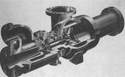
FIG. 1 Typical expander/compressor assembly. ( Atlas Copco/Mafi-Trench
Corp., Santa Maria, CA.)
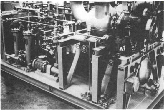
FIG. 2 Expander system for a petrochemical process. ( Atlas Copco/Mafi-Trench
Corp., Santa Maria, CA.)

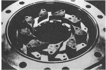
FIG. 3 Expander inlet guide vanes. ( Atlas Copco/Mafi-Trench Corp., Santa
Maria, CA.)
EXPANDER DESIGN AND CONSTRUCTION
In the typical process-type expanders, the shaft power is absorbed and used by a single-stage centrifugal compressor. The compressor is mounted on the same shaft as the expander, providing a simple and compact design. An expander of this type is shown in FIG. 1. The expander flow enters through the flange at the upper left, flows through the inlet guide vanes (nozzles) and expander wheel, and exists through the flange at the lower left. The compressor flow enters the flange at the right, is compressed, and exits at the top center. Bearings and seals are located between the two wheels on a short rigid shaft. This arrangement is typical of expanders used for natural gas processing, petrochemical processes, and expansion of air and nitrogen in air separation and nitrogen liquefaction plants.
A complete dual expander system including two expanders and all required auxiliary equipment and local control panel for a petrochemical process application is shown in FIG. 2. Radial flow expanders for process applications must be capable of reliable and efficient operation over a relatively wide range of flow rates. To accomplish this, these machines incorporate variable inlet guide vanes or "nozzles," as shown in FIG. 3. This design uses an externally mounted pneumatic actuator to control the opening of the guide vanes and therefore the expander flow and resultant power output. An internally mounted fulcrum mechanism translates the linear motion of the pneumatic actuator into rotation of a ring that pivots each guide vane on a hardened pin. The reliable operation of this mechanism is critical to the control of the expander and the process, and therefore the design details and materials of construction must be carefully selected to avoid galling and excessive wear during operation.
Expander and compressor wheels are usually constructed of high-strength aluminum alloy. The low-density and relatively high-strength aluminum alloy is ideally suited to these wheels, as they operate at moderate temperature on relatively clean gas and the low-density alloy permits minimizing the weight of the wheels, which is desirable to avoid critical speed problems. A typical expander wheel is shown in FIG. 4. This wheel was produced by machining from a solid aluminum alloy forging. This construction has been shown to be superior to wheels produced by welding, brazing, or casting.
The rotor assembly (expander wheel, shaft, and compressor wheel) for a typical cryogenic process expander is shown in FIG. 5. The expander wheel is on the fight and the compressor wheel on the left. The compact and rigid design of the rotor is apparent in this figure.
Labyrinth-type seals are used between the expander and compressor wheels and the oil-lubricated bearings. These seals prevent mixing of the process gas and lube oil by injecting filtered buffer gas (seal gas) in the middle of the labyrinth and allowing the gas to flow both toward the process and the beating. The stationary and rotating elements of a stepped-type labyrinth seal for a process expander are shown in FIG. 6.
Process expanders generally use a combination journal and thrust beating similar to that shown in FIG. 7. An essentially identical bearing assembly is located near the expander wheel and compressor wheel, providing thrust capacity in both directions. Since both the thrust and journal beatings are hydrodynamic, there is no bearing wear during normal operation.

FIG. 4 Typical process expander wheel. ( Atlas Copco/Mafi-Trench Corp.,
Santa Maria, CA.)
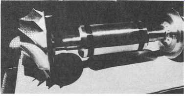
FIG. 5 Rotary assembly for process expander/compressor. (Atlas Copco/Mafi-Trench
Corp., Santa Maria, CA.)

above: Mafi-Trench "Mag Rotor"
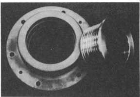
FIG. 6 Expander labyrinth seal assembly. ( Atlas Copco/Mafi-Trench Corp.,
Santa Maria, CA.)
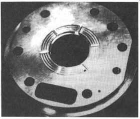
FIG. 7 Combination journal and thrust bearing. ( Atlas Copco/Mafi-Trench
Corp., Santa Maria, CA.)
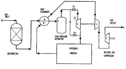
FIG. 8 Cryogenic turboexpander plant. ( Atlas Copco/Mafi-Trench Corp.,
Santa Maria, CA.)
TYPICAL APPLICATION
A simplified schematic diagram of a cryogenic turboexpander plant is shown in FIG. 8. Hundreds of such plants are in operation throughout the world, extracting the heavier hydrocarbons from natural gas. The process is based on providing the required refrigeration by direct expansion of the process gas in a single-stage radial expander similar to that shown in FIG. 1.
In this process, the gas is first dehydrated to prevent the formation of ice or hydrates within the cryogenic portion of the plant. Next, the gas is cooled by heat exchange with cold residue gas. This cooling usually results in some condensation.
The condensed liquids are removed by a high-pressure separator before reaching the expander. The gas is then expanded through the expander, producing a relatively large temperature drop and substantial liquid formation. Residue gas from the cryogenic process is used to cool the expander inlet gas and is then compressed by the expander driven "boost" compressor. Additional residue gas compression is then required to increase the pressure to a level near the inlet to the plant.
OPERATION
Since essentially all of the turboexpander plant flow passes through both the expander and the boost compressor, it’s possible to efficiently vary the plant flow rate using the expander inlet guide vanes. The expander shaft speed is allowed to vary freely in response to changing plant flow rate. This method of control has been shown to produce excellent off-design performance. During operation at reduced flow, the boost compressor will tend to operate near surge. It’s therefore essential that the compressor be provided with an adequate surge control system.
If the compressor is allowed to operate in surge for any significant length of time, damage will occur to the bearings and seals due to the resulting shaft vibrations.
(See the section on centrifugal compressors for a more detailed description of surge.) If, during operation, solid particles are carded into the expander, the centrifugal forces created by the expander wheel will tend to cause them to be centrifuged out and strike the underside of the inlet guide vanes. This can cause erosion damage to both the inlet guide vanes and the expander wheel blade tips. To minimize this type of damage, it’s necessary to provide a 60- to 80-mesh screen upstream of the expander. The screen should be capable of withstanding a 100- to 200-psi differential pressure, and the differential pressure should be monitored continuously.
Noncontacting shaft vibration monitoring equipment has been shown to be very useful in monitoring the mechanical condition of expanders. It’s important to keep accurate logs of vibration. These data can be particularly useful in evaluating the expander condition after a major process upset or expander trip.
As with all high-speed rotating equipment, the cleanliness and quality of the lube oil and seal gas should be carefully maintained. Routine sampling and spectrographic analysis of the lube oil to detect the buildup of water, particulate, or trace contaminants is recommended.
Any condition that causes an expander trip shuts down the expander by rapidly (in less than one-half second) closing the expander inlet trip valve. If the trip is due to an interruption in lube oil supply, the oil flow during coastdown must be provided by an accumulator. The accumulator must be adequately sized, and the precharge pressure must be properly maintained.
It’s possible that an expander will slowly rotate or "windmill" due to leaky process valves on the expander or compressor during shutdown. If the lube system is off during this time, damage to the bearings can occur. This type of damage is more common than might be expected because the rotating speed during windmilling may be so slow that it does not indicate on the electronic tachometers on process expanders.
MAINTENANCE
Expander operating reliability has been shown to be strongly dependent on the quality of routine maintenance. As a minimum, the following items should be included in any maintenance program.
++ Maintain proper expander data logs to be used for trend analysis.
++ Provide adequate surge protection for the compressor.
++ Regularly sample and analyze the lube oil for contamination.
++ Provide a 60-to 80-mesh expander inlet screen and differential pressure monitor.
++ Install a compressor discharge check valve to prevent back flow on shutdown.
++ Maintain process valves for tight sealing to prevent expander "wind-milling" during shutdown.
++ Maintain proper filtration of seal gas.
++ Assure that the expander inlet trip valve closes in less than one-half second on trip.
++ Verify all expander alarm and shutdown functions at least yearly.
More info: http://en.wikipedia.org/wiki/Turboexpander