AMAZON multi-meters discounts AMAZON oscilloscope discounts
Steam turbines occur mainly in mechanical drive applications in the process
engineer's world. When the plant also has small power generation requirements,
the power plant selected is generally a gas turbine. Such is the case at Esso's
Sriracha refinery in Thailand which owns two ABB GT35s. Larger facilities often
find it economical to make most of their own power. The Syncrude Tar Sands
facility in northern Alberta, Canada which refines 170,000 barrels of oil a
day is such a facility. Syncrude uses a combination of gas and steam turbines.
There is also a current emerging global trend that may grow: for oil and gas
and petrochemical facilities to make their own power and sell the excess to
the local national power grid. However, due to the relative proportion of mechanical
drive versus power generation applications that a process engineer is likely
to see, this section is essentially devoted to mechanical drive turbines. 
above: YR Turbines from Elliot, USA.
In steam turbines, apart from the load factor (close to, or at base or steady load in most power generation applications), the subdivision between mechanical and power generation applications is size. The approximate cut-off for mechanical drive applications is about 100 MW. Sizes above 100 MW are not normally used in compressor drive services.
Although less versatile than the gas turbine (a steam plant has to provide design inlet pressure steam, before the steam turbine can run), steam turbines are reliable and easy to operate. The global distribution of natural gas still favors the utilization of steam turbines. At recent tally, the world has about 70 years of natural gas supply left. This figure increases as gas exploration becomes more ambitious. However, as the world has 200 to 300 years worth of coal, a great deal of that in the newly developing global regions, it's easy to see which fuel comes out ahead. Political factors also enter the selection issue.
Note also that although steam turbine plant systems have been touted as having a slower response time than gas turbines, that gap is diminishing with new advances in steam turbine control systems.
Environmental considerations caused by steam turbine plant boiler emissions need not be an issue for new plants, if current technology is used. This technology is described in Environmental Engineering and Management: Sustainable Development for the Power Generation, Oil and Gas and Process Industries in far more detail than the scope of this section allows. That text would be useful for any process engineer who has to face new equipment selections, plant expansion design, changes in environmental legislation or major plant refurbishments today.
MECHANICAL DRIVE STEAM TURBINES
Steam turbines for mechanical drive applications were among the first real machines to usher in the Age of Industrialization. In 1629, an Italian inventor, Giovanni de Branca, envisioned a boiling pot whose nozzle opening was aimed against the paddle wheels of a roasting spit. Clearly, then, the use of expanding steam to turn a shaft is anything but a new idea.
By now, hundreds of thousands of steam turbines are installed and working in every conceivable type of process plant the world over. As shown in TBL. 1, inlet steam pressures range from a few pounds per square inch (psi) to over 2000 psi (140 bar) and power output covers the field from a single kilowatt (kw) in the emergency lube oil pump driver to almost 100,000 kw in large compressor drive applications at modem petrochemical plants. This should be no surprise, since the ability to efficiently convert large amounts of heat energy into mechanical work makes the steam turbine the logical choice for many industrial drive applications. Its reliability, smoothness of operation, and versatility also contribute to its popularity.
Before discussing turbine selection, let's review how a steam turbine converts the heat energy of steam into useful work.
The nozzles and diaphragms in a turbine are designed to direct the steam flow into well-formed, high-speed jets as the steam expands from inlet to exhaust pressure. These jets strike moving rows of blades mounted on the rotor. The blades convert the kinetic energy of the steam into rotation energy of the shaft.
In a reaction turbine, the steam expands in both the stationary and moving blades. The moving blades are designed to utilize the steam jet energy of the stationary blades and to act as nozzles themselves. Because they are moving nozzles, a reaction force- produced by the pressure drop across them- supplements the steam jet force of the stationary blades. These combined forces cause rotation.
To operate efficiently, the reaction turbine must be designed to minimize leakage around the moving blades. This is done by making most internal clearances quite small. The reaction turbine also usually requires a thrust balance piston (similar to large centrifugal compressors) due to the large thrust loads generated.
Because of these considerations, the reaction turbine is less often used for mechanical drive in the United States, despite its higher initial efficiency. However, reaction turbines are quite often used in other parts of the world. This text will explain them later. Moreover, since impulse and reaction turbines share many construction details and nomenclature, the reader is encouraged to become familiar with both.
===
TBL. 1
Unit Typical Steam and Power Conditions for Process Plant Turbines Steam Power Small Medium Large Very large 150-400 psig; 500-750~ (10-27 bar; 260-400 ~ 400-600 psig; 750-825 ~ (27-41 bar; 400-440 ~ 600-900 psig; 750-900~ (41-62 bar; 400-482 ~ 900-2,000 psig; 825-1000 ~ (62-140 bar; 440-538 ~ 1-1,000 HP (0.75-750 kw)
1,000-5,000 HP (750-3,750 kw)
5,000-60,000 HP (3,750-45,000 kw)
15,000-120,000 HP (11,200-90,000 kw)
===
IMPULSE STEAM TURBINES
The impulse turbine has little or no pressure drop across its moving blades. Steam energy is transferred to the rotor entirely by the steam jets striking the moving blades ( FIG. 1). Since there is theoretically no pressure drop across the moving blades (and thus no reaction), internal clearances are large and no balance piston is needed.
These features make the impulse turbine a rugged and durable machine that can withstand the heavy-duty service of today's mechanical drive applications. Steam turbine materials are tabulated in TBL. 2.
====
Vj (Jet velocity] V b (blade velocity] = 0
.....
If the turbine rotor is locked, the steam jet exerts maximum force on the blades, but no work is done since the blade doesn't move.
9 = V j/4
If the blade is moving at ~ of the jet velocity, the force on the blade is reduced, but some work is done by moving the blades.
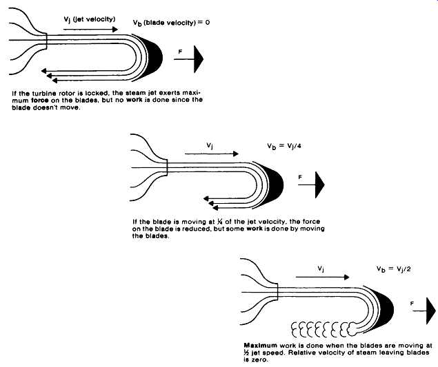
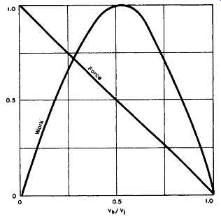
FIG. 1
Maximum work is done when the blades are moving at let speed. Relative velocity of steam leaving blades is zero.
Vb/vj
The impulse principle. (Elliott Group, Jeannette, PA.)
====
TBL. 2 Typical Standards Materials of Construction for Mechanical Drive Steam Turbines
===
Velocity-Compounded (Curtis) Staging
A Curtis stage ( FIG. 2) consists of two rows of moving blades. Stationary nozzles direct the steam against the first row; reversing blades (not nozzles) then redirect it to the second row.
The large pressure drop through the nozzle produces a high-speed steam jet.
This high velocity is absorbed in a series of constant pressure steps (see below). The two rotating rows of blades make effective use of the high-speed jet, resulting in small wheel diameters and tip speeds, fewer stages, and a shorter, more rugged turbine for a given rating.
Pressure-Compounded (Rateau) Staging
Again referring to FIG. 2, we observe how in Rateau staging the steam path is slightly different. Here the heat energy of the steam is converted into work by stationary nozzles (diaphragms) directing the steam against a single row of moving blades. As in a Curtis stage, pressure drops occur almost entirely across the stationary nozzles.
Turbine Configuration Overview
Single-flow condensing units ( FIG. 3) require less steam for a given horsepower than other types. They expand steam from inlet pressure to a pressure less than atmospheric. The exhaust pressure is maintained by a condenser, providing for recovery of the spent steam. A condensing unit thus minimizes the need for makeup water. Because of these advantages, the straight condensing turbine is much in demand, as evidenced by the literally thousands of units installed world-wide.
Double-flow condensing units ( FIG. 4) are very similar to single-flow units except that the last-stage flow is divided between two rows of blades. This enables a double-flow turbine to operate at higher horsepowers and speeds than single-flow units of similar steam conditions.
Automatic extraction units are schematically represented in FIG. 5. Extraction turbines are used when there is a need for process steam at a pressure between turbine inlet and exhaust pressures. They are designed to simultaneously maintain the desired extraction steam pressure and the speed of the driven machine. They can do this even though the demand for extraction steam and the horsepower requirements of the driven unit may vary over a wide range.
Noncondensing steam turbines ( FIG. 6) exhaust steam at greater than atmospheric pressure and while it still contains a great deal of energy. It can therefore be used for other purposes in a given plant. Units of this type are much more compact than condensing turbines of the same horsepower due to the smaller volume of steam handled at the exhaust end.
FIG. 7 depicts three typical rotor categories: single-flow condensing, double-flow condensing, and noncondensing.
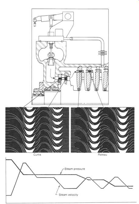
FIG. 2 Steam flow through turbine stages. S = Stationary. (Elliott Group, Jeannette, PA.)
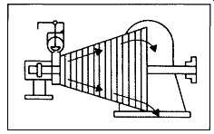
FIG. 3 Single-flow condensing turbine. (Elliott Group, Jeannette,
PA.)
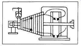
FIG. 4 Double-flow condensing turbine. (Elliott Group, Jeannette,
PA.)
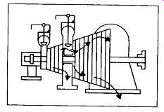
FIG. 5 Automatic extraction turbine. (Elliott Group, Jeannette, PA.)
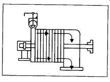
FIG. 6 Noncondensing steam turbine. (Elliott Group, Jeannette, PA.)
Turbine Components
Casing Overview. A good casing should be just thick enough to contain the steam pressure for which it’s designed. Overly thick walls act as heat sinks and can restrain expansion and contraction and lead to premature cracking.
Thin, contoured walls prevent large gradients between inside and outside "skin" temperatures. A turbine casing designed this way conducts heat rapidly. This protects against cracking of the nozzle partitions (critical area) and assures long life for casings subjected to load changes and start-stop operation.
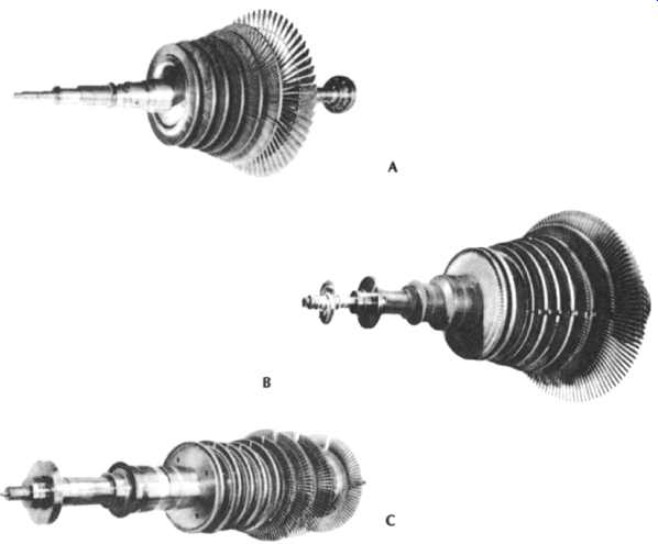
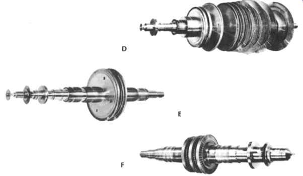
FIG. 7 Principal rotor categories: Single-flow condensing (A, B), double-flow
condensing (C, D), noncondensing (E, F). (Elliott Group, Jeannette,
PA.)
This casing philosophy is carried a step further on turbines designed for 2000 psi and 950~ (140 bar and 510~ The nozzle chambers and partitions are free of both the front and side walls. The result, in effect, is a double-casing that relieves the internal stress in an area where there can be large inside-outside temperature differences.
Casing Construction. A typical steam turbine casing consists of a steam chest, intermediate barrel section, and separate exhaust casing. To prevent leakage at the high-pressure end, the steam chest and barrel section are often cast as one piece.
This permits the vertical casing joint to be made at the low-pressure end.
The high-pressure end of the turbine is supported by the steam end bearing housing. This housing is flexibly supported to permit axial expansion caused by temperature changes. The exhaust casing is centerline-supported on pedestals that maintain alignment with the driven machine while allowing for lateral expansion.
FIG. 8 and 9 illustrate important casing details.
FIG. 8 Steam turbine casing components. (Elliott Group, Jeannette, PA.)
Steam Turbine Rotors. Steam turbine rotors are either of the solid or built-up type.
Because each has its advantages, the user should not be tied to any one method of rotor construction. Operating conditions often call for a solid rotor, but sometimes the user may choose between the two or accept a recommendation from capable manufacturers.
With solid rotor construction, the shaft and disks are one piece. These rotors are generally used in units operating at high temperatures and/or high speeds.
Built-up rotors ( FIG. 10) cost less to make, less to buy, and are easier to repair if damaged. They are generally used in units operating at lower temperatures and speeds. Speeds are generally limited by the shrink fit required to overcome centrifugal growth of the disk.
With either solid or built-up construction, shaft and disk materials must be selected to match the user's speed and temperature conditions. The shaft must be accurately proportioned to make sure that critical speeds are safely outside the operating speed range. Disk profiles should be designed to minimize centrifugal stresses, thermal gradients, and blade loading at the disk rims.
Combination solid and built-up rotors are also available. FIG. 11 shows a seventeen-stage, 28,000 HP (21 MW) rotor weighing 17,000 lbs. (7700 kg) and embodying the combination principle.
Blades. The size and configuration of turbine blades depend on the operating conditions imposed on them. Machinery engineers have been designing blades to match horsepower, speed, and all types of steam conditions for many years. This continuing accumulation of blade knowledge has provided a wide selection of tested and proved blade designs. The blade performance record of reputable manufacturers usually reflects substantial design and manufacturing experience.
FIG. 12 illustrates first-stage blades that have to withstand punishment of steam at its highest pressure and temperature. The blade at left is used for 2000 psi (140 bar) service; others are for lower pressures. A chromium stainless steel alloy, selected for its strength, erosion/corrosion resistance, and damping qualities is used on all blades. Last-stage blading is con figured to efficiently expand large volumes of steam. Consequently, the blades are often considerably larger than those located in the higher pressure regions of a steam turbine.
Nozzle Rings and Diaphragms. A stage in multistage turbines consists of both rotating and stationary blades. The stationary blades can be part of a nozzle ring or a diaphragm. In either case, their function is to direct steam onto the rotating blades, turning the rotor and producing mechanical work.
The first-stage nozzle ring is made by milling steam passages into stainless steel blocks, which are then welded together ( FIG. 13). Other manufacturing methods are, of course, available.
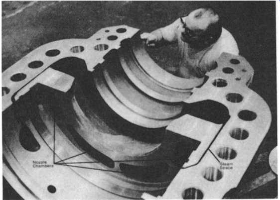
FIG. 9 Steam end (2000 psi; 140 bar) showing steam space between nozzle
chambers and front and side walls. This allows nozzle chambers to expand
and contract freely in response to load and temperature changes. (Elliott Group, Jeannette, PA.)
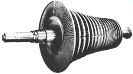
FIG. 10 Typical built-up single-flow rotor with 14-inch (360-mm) last-stage
blades. Every disk is shrunk and keyed to the shaft. (Elliott Group, Jeannette,
PA.)
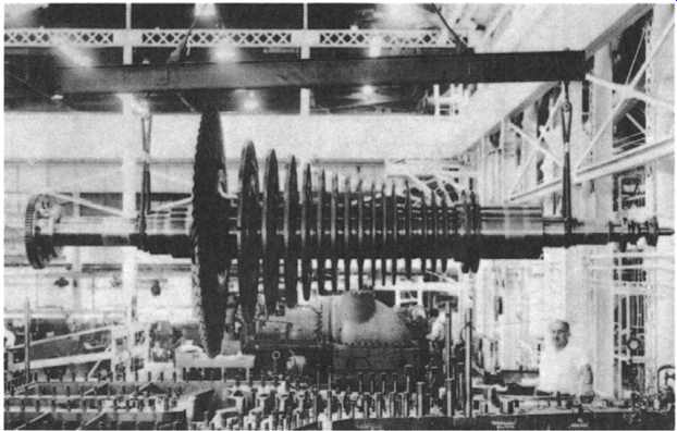
FIG. 11 Combination solid and built-up rotor for 28,000-HP (21-mW) steam
turbine. (Elliott Group, Jeannette, PA.)
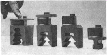
FIG. 12 First-stage blades for steam turbines.
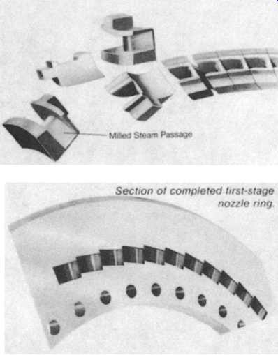
FIG. 13 First-stage nozzle ring. (Elliott Group, Jeannette, PA.)
The nozzles in the intermediate pressure stages are formed from stainless steel nozzle sections and inner and outer bands. These are then welded to a round center section and an outer ring, as shown in FIG. 14.
Low-pressure diaphragms of condensing turbines are often made by casting the stainless nozzle sections directly into high-strength cast iron. This design ( FIG. 15) includes a moisture catcher to trap condensed droplets of water and keep them from re-entering the steam path. These diaphragms can also be completely fabricated, if desired, at extra cost.
FIG. 16 illustrates steam turbine diaphragms as ultimately installed. The figure shows how the steam goes through the nozzles and strikes the rotor blades, causing rotation. Each diaphragm is located in its own groove in the casing. The keyway assures alignment of the diaphragm halves and helps minimize steam leakage across the split line.
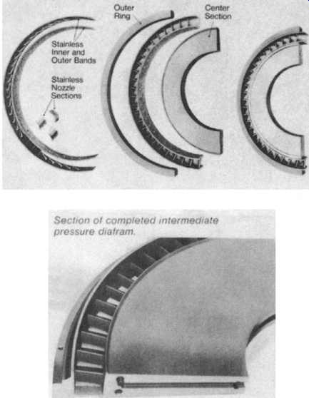
FIG. 14 Intermediate pressure diaphragm.
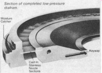
FIG. 15 Low-pressure diaphragm. (Elliott Group, Jeannette, PA.)
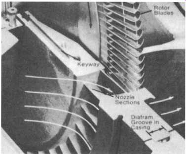
FIG. 16 Passage of steam through nozzles in diaphragm. (Elliott Company,
Jeannette, PA.)
Thrust Bearings.Thrust bearings in modern steam turbines must withstand greater loads and higher speeds. The double-acting, self-leveling, fully equalizing Kingsbury type best meets these demands. It’s long-wearing, requires little maintenance, and is capable of handling variable speeds.
As the wedge-shaped oil film is formed between the thrust collar and the surface of each shoe ( FIG. 17), the upper and lower leveling plates assure that the thrust load is distributed evenly among the shoes. The base ring then transmits this thrust load to the beating housing. Stops prevent the base ring from rotating with the shaft.
Thrust bearings are generally sized to provide thrust capacity well in excess of that required for normal operating conditions.
Journal Bearings. The turbine rotor runs in positively aligned, pressure-lubricated journal bearings that are horizontally split and lined with babbitt of the highest quality. Pressure-dam or tilting shoe bearings are used when required to assure bearing stability throughout the speed range.
Pressure-dam journal beatings ( FIG. 18) are generally used in high-speed units. This type of bearing is produced from a standard liner in which "dams" have been machined to create a "pressure pad" of oil. This pad forces the shaft to remain in position in the lower beating liner, thus maintaining proper shaft attitude angle.
Tilting shoe journal bearings, shown in FIG. 19 with five shoes (or pads), help ensure rotor stability.
Labyrinth Seals. Experience has proved the labyrinth seal to be most reliable for steam turbines. It forms an effective seal without contact between its component parts, which means turbines will rarely if ever be shut down for seal maintenance.
The function of the seal, simply put, is to keep steam in and air out of the turbine where the rotor passes through the casing. It restricts steam leakage along the shaft by using the sealing strips on the shaft sleeve to form a "labyrinth" that hinders the flow of steam ( FIG. 20). In noncondensing or back-pressure turbines, the labyrinth seal must prevent steam leakage out of the casing at both inlet and exhaust because these pressures are greater than atmospheric. In condensing turbines, the pressure at the exhaust end is less than atmospheric. In this case, the labyrinth seal and sealing steam are used to prevent the flow of air into the casing.
Extraction Control
The use of extraction steam has gained wide acceptance in industry today. An extraction turbine can supply steam at some constant pressure between turbine inlet and exhaust pressures. This flexibility can be a great asset when designing a plant steam balance.
To automatically supply extraction steam, a second steam chest and a pressure control system are added to the speed control (governing) system of the turbine.
This creates, in effect, two turbines on one shaft.
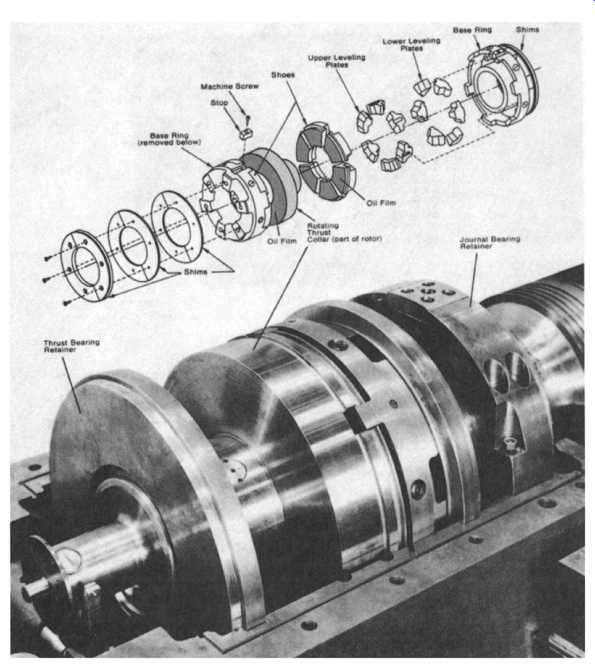
FIG. 17 Self-leveling thrust bearing (Kingsbury-type) installed in modem
steam turbine. (Elliott Group, Jeannette, PA.)
Extraction steam pressure and turbine speed are controlled by the extraction regulator as follows:
Constant Extraction Demand. Let's assume that extraction steam demand is constant, but the load on the turbine is reduced slightly and it begins to increase speed. The governor calls for reduced steam flow to the turbine.
The regulator is designed to reduce the steam flow proportionally through both the steam inlet valves and extraction valves. Extraction flow, therefore, remains unchanged, while both inlet and exhaust flows are reduced.
This diminished steam flow through the turbine decreases the power developed, and the turbine slows to its set speed. ( FIG. 21A).
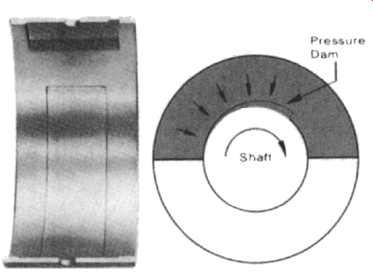
FIG. 18 Pressure-dam journal bearing. (Elliott Group, Jeannette,
PA.)
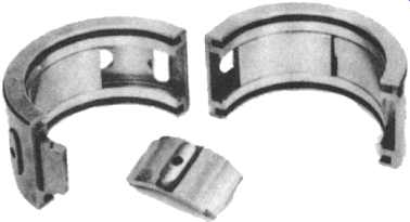
FIG. 19 Tilting-shoe journal bearing. (Elliott Group, Jeannette,
PA.)
Constant Load. Let's assume that the load on the turbine is constant, but there is a change in the process and the demand for extraction steam decreases. The extraction pressure increases, thus compressing the bellows in the regulator and rotating the three-arm linkage. This simultaneously closes the inlet valves and opens the extraction valves.
The inlet and extraction flows are thus decreased, while the exhaust flow is increased. Speed holds at setpoint because the three-arm linkage is proportioned to maintain a constant total horsepower developed by the rotor during these changes in extraction flow ( FIG. 21B). In actual operation, both speed and extraction steam demands are constantly changing, and the sequences described are occurring simultaneously.
When excess steam is available, it can be "induced" into the turbine and expanded to exhaust pressure. Major manufacturers of steam turbines can supply automatic extraction units, automatic induction units, or a combination of the two.
It should also be stressed that fully electronic controls are sometimes an attractive feature that could be considered instead of the more traditional, time-tested mechanical controls. Many of the 1980-vintage steam turbines are fitted with highly reliable electronic controls.
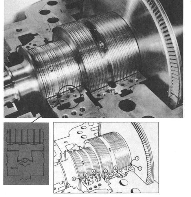
FIG. 20 Labyrinth seal details. (A) Labyrinth seal showing how high and
low sealing strips combine with the stationary baffle to hinder the flow
of steam. The spring allows the stationary baffle to move away from the shaft
if a rub occurs. The heat generated is absorbed by the stationary baffle.
This protects the shaft and minimizes rotor damage. (B) Leakage flow and
sealing steam arrangement for steam end of condensing turbine. Conditions
that follow are typical values: (1) First-stage pressure equals 300 psia
(21 bar) at full load. (2) Leakoff to turbine stage at approximately 125
psia (8.7 bar). (3) Leakoff to turbine stage at approximately 40 psia (2.8
bar). (4) Sealing steam at start-up is approximately 18 psia (1.25 bar).
(5) Steam and air drawn to gland condenser at approximately 13.5 psia (0.9
bar). (6) Small amount of atmospheric air drawn in. (Elliott Group,
Jeannette, PA.)
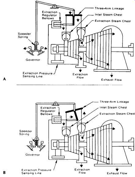
FIG. 21 Constant extraction demand (A) versus constant load output (B).
(Elliott Group, Jeannette, PA.)
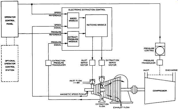
FIG. 22 Electronic extraction control for steam turbine. (Elliott Group,
Jeannette, PA.)
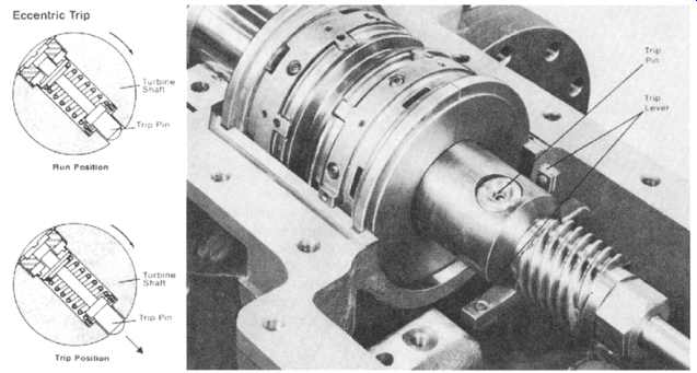
FIG. 23 Eccentric overspeed trip device. (Elliott Group, Jeannette,
PA.)
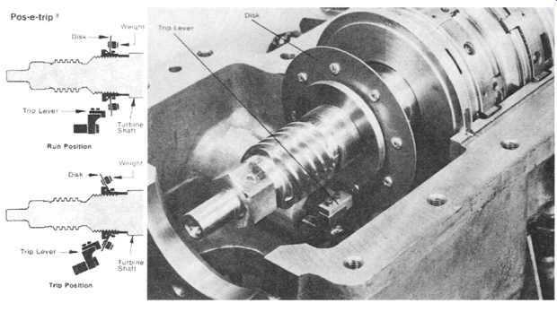
FIG. 24 Disk-type overspeed device. (Elliott Group, Jeannette, PA.)
An electronic extraction control system for a turbine driving a compressor is shown in FIG. 22. Speed and pressure signals are fed to the control and electrically compared with the speed and pressure reference set points. Corrective signals are generated and sent to the inlet and extraction servo-motors. The optional operator control station is just one of a wide variety of optional features available with this type of control.
Trip Devices. Steam turbines must be protected against excessive speed by automatic overspeed trip devices. These devices are either of the mechanical or electronic type. Mechanical overspeed devices are based on the centrifugal force principles as shown in FIG. 23 and 5-24. Upon actuation of the trip lever, hydraulic oil is dumped from a pressurized cylinder that normally holds inlet steam or trip valves open. When depressurization occurs, these valves close instantly.
Electronic overspeed devices operate on a somewhat similar principle. Their actuation results in the opening of a solenoid dump valve that de-pressures the hydraulic cylinder that normally keeps the inlet and trip valves open.
REACTION STEAM TURBINES
Our introductory comments on steam turbines made the point that steam turbines extract heat energy from the steam and convert it into mechanical work. Heat and mechanical work are both forms of energy, and, therefore, can be converted from one to the other.
First, heat energy is converted into velocity (kinetic) energy. In this first step, steam expands in a nozzle discharging at high velocity. The total heat (enthalpy) of the steam is converted to kinetic energy (velocity). Second, a steam turbine does mechanical work by virtue of the steam velocity that strikes moving blades. There are two types of stages to convert this velocity energy into usable work, namely, impulse and reaction. With an impulse design, the pressure drop is taken across the nozzles only, whereas with reaction design the drop is evenly distributed across the nozzle and blades. If the nozzle is fixed and the force of the jet is directed against a crescent shape (the blade), the jet's impulse force pushes the blade in the direction of the jet. Further, the leaving velocity is less than the initial jet velocity. Such an example would be a water hose jetting water against a wall. If the nozzle is free to move, the reaction pushes against the nozzle and it will travel in a direction opposite to the jet. The leaving velocity is greater than the jet velocity. An example would be a revolving lawn sprinkler.
The basic characteristics of impulse-type turbines and reaction-type turbines can be summarized as follows. In impulse turbines we find the following:
++. Large bucket clearances permit quicker loading with minimal danger from thermal stress.
++ Since most of the pressure drop is in stationary nozzles, efficiency does not depend on blade clearances.
++ Low thrust generation.
In reaction turbines, we note the following:
++ Expansion takes place in stationary nozzles and moving blades.
++ More bucket sealing (sealing strips) is required at the end of blades.
++ Efficiency is theoretically greater but depends on close clearances.
++ The so-called greater efficiency of a reaction machine over an impulse machine in practice becomes a function of the staging (number of stages, efficiency of stages available, etc.). A reaction machine will have more stages because to keep losses to a minimum, the pressure drop per stage must be kept low.
++ Reaction turbines require larger thrust bearings and/or a balancing piston.
Reaction staging is similar in concept to Rateau staging except that pressure drop occurs through both the stationary nozzle and matching blades. FIG. 25 shows reaction staging and can readily be compared with Rateau staging.
A cutaway view of a typical reaction-type turbine is shown in FIG. 26. It highlights the principal components as follows.
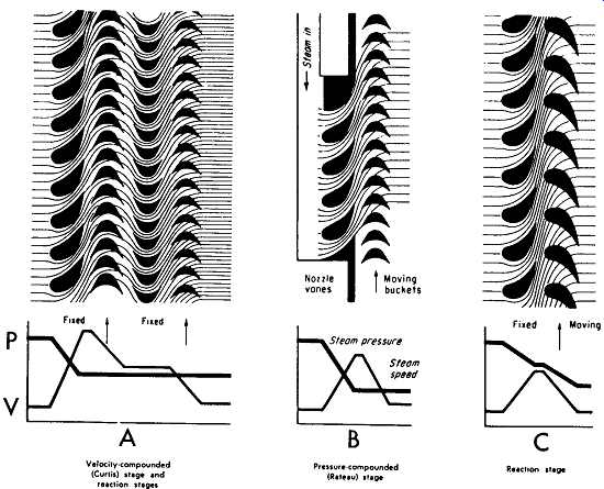
FIG. 25 Different types of stages employed in modem steam turbines. (Elliott Group, Jeannette, PA. )
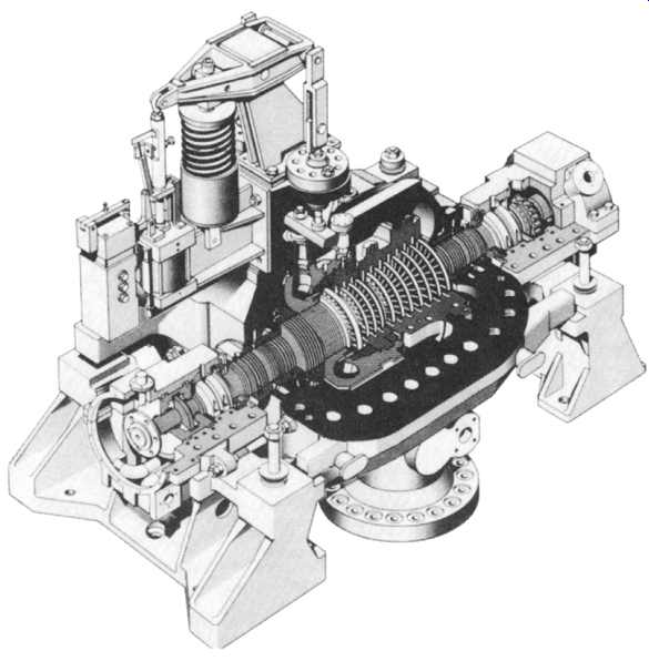
FIG. 26 Cutaway view of a typical reaction-type steam turbine. (Siemens
Energy and Automation, Inc., Medium Power Generation Division, Bradenton,
FL.)
Casing and Guide Blade Carriers
To achieve satisfactory performance with the high steam pressures involved and to simplify erection and overhauls, a double-shell casing is used. The outer shell is split horizontally at the machine axis, the top half incorporating the integrally cast admission chest. This is in the form of a transverse tube with an opening at each end for assembly. The emergency stop valve body is welded to one end of the tube.
The two halves of the casing are flanged and bolted together. The casing flange bolts are heated to a predetermined temperature when being fitted. The cooling of the bolts prestresses them exactly to a predetermined value.
The guide blades are fitted in carriers. The front carrier is mounted in the one- piece inner shell, while the real carrier is mounted directly in the outer shell. The longer machines incorporate an additional carrier. The unsplit inner shell allows the useful feature of a split outer casing to be retained while at the same time offering the advantages of the "barrel" type of construction. The inner shell is shown in FIG. 27. The front guide blade carder is split axially and clamped together by a conical ring. It’s located centrally in the inner casing by a bayonet coupling that is pinned to prevent it from turning.
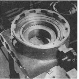
FIG. 27 One-piece high-pressure inner casing for reaction turbine. (Siemens
Energy and Automation, Inc., Medium Power Generation Division, Bradenton,
FL.)
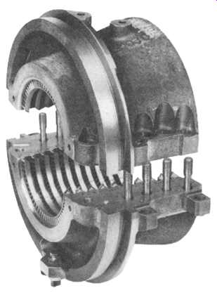
FIG. 28 Rear guide blade carrier for reaction turbine. (Siemens Energy
and Automation, Inc., Medium Power Generation Division, Bradenton, FL.)
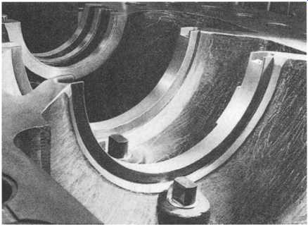
FIG. 29 Fitted eccentric pin for internal component alignment of reaction
turbine. (Siemens Energy and Automation, Inc., Medium Power Generation Division,
Bradenton, FL. )
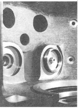
FIG. 30 Vertical thrust balancing chambers with L-ring sealing to casing
bottom half (Siemens Energy and Automation, Inc., Medium Power Generation
Division, Bradenton, FL.)
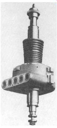
FIG. 31 Turbine rotor complete with inner casing and front guide blade
carrier. (Siemens Energy and Automation, Inc., Medium Power Generation Division,
Bradenton, FL.)
FIG. 28 shows the completely assembled rear blade carder, which is kinematically supported in the outer casing. The guide blade carders are aligned in the bottom half of the casing before final assembly.
The steam pressure in the annular space between the inner and outer shells is approximately half the initial steam pressure. This means that both the inner and outer shells are subjected to relatively low stresses. Since there is only a small difference in the temperature of the steam inside and outside the inner shell when the turbine is running normally, thermal stresses are also minimal. The largely symmetrical shape ensures that thermal expansion is uniform at all sections.
The fact that the front part of the outer casing is subjected to only half the initial steam pressure and the rear part of the casing to the exhaust pressure means that flanges and bolts can be of a size consistent with their reduced stress. The inner shell rests on its integrally cast brackets in the bottom half of the outer casing. Eccentric pins ( FIG. 29) are incorporated to adjust the position of the inner shell in relation to the outer casing and to align the rear guide blade carrier in the outer casing.
Self-sealing, L-section rings free to expand in any direction are used for the seal between the admission chest and the inner shell.
The initial steam entering the various nozzle boxes of the admission chest gives rise to a downward thrust on the inner casing. This thrust is partially compensated by allowing steam from the two outer nozzle boxes to pass through holes in the bottom of the inner casing and build up an opposing force on the underside of the casing in two small chambers of appropriate cross-sectional area sealed from the outer casing by L-section rings ( FIG. 30).
The exhaust, gland, and drain connections are made to the bottom half of the outer casing with the result that only the initial steam line must first be removed to lift the top half of the casing. Since the bottom half remains in its aligned position on the pedestals, the amount of work involved in overhauls and inspections is considerably reduced. Once the top half of the casing has been lifted, the rotor, complete with the inner casing and front guide blade carrier, can be taken out ( FIG. 31). The combined weight of these parts is only approximately one eighth of the total weight of the turbine.
Rotor and Blading
The solid rotor shaft and control stage wheel are forged of one piece. The individual blades, which are machined from the solid, have integral shrouding and a T-root that fits into a groove in the rotor shaft. The drum blading is approximately 50 percent reaction.
Blade Tip Sealing
The rotor blades are milled from the solid together with the shrouding. After they have been fitted in the rotor groove, the shrouding forms a complete ring, which is then skimmed. A circumferential step is formed in the surface of the shrouding, which, together with the sealing strips caulked into the casing opposite the shrouding, produces an efficient sealing effect. Riveted shrouding is used for the guide blades as they are not subjected to centrifugal force. A labyrinth sealing effect is again produced by caulking sealing strips in the rotor opposite the shrouding.
FIG. 32 shows some shrouded blading and also a diagrammatic section of the tip sealing employed. The radial clearance may be kept extremely small to reduce losses without adversely affecting operational reliability. Should mal-operation cause contact to occur, the sealing strips will be rubbed away without producing a dangerous rise in temperature, and they can be replaced at the next overhaul without disturbing the blading in any way.
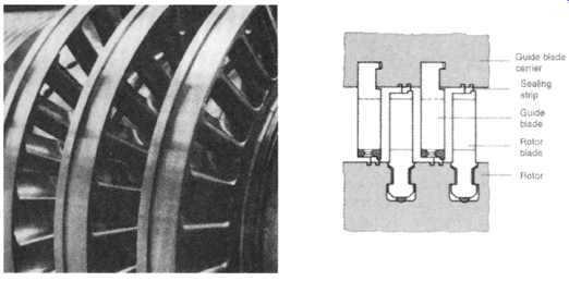
FIG. 32 Tip sealing of blade by integral shrouding. (Siemens Energy and
Automation, Inc., Medium Power Generation Division, Bradenton, FL.)
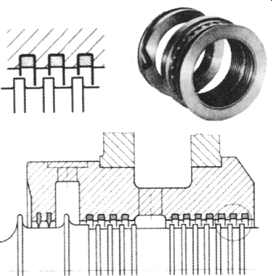
FIG. 33 Labyrinth shaft gland. (Siemens Energy and Automation, Inc., Medium
Power Generation Division, Bradenton, FL.)
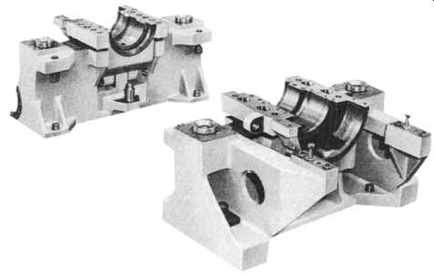
FIG. 34 Front and rear bearing pedestals for reaction turbine. (Siemens
Energy and Automation, Inc., Medium Power Generation Division, Bradenton,
FL.)
Shaft Glands
The points where the shaft passes through the casing are sealed by means of labyrinth glands, which are composed of sealing strips in the stationary part projecting into grooves in the turbine rotor shaft ( FIG. 33). Any steam leaking through the gland is drawn off at an intermediate stage to a region of lower pressure in the turbine or to a special condenser in order to limit the amount of steam discharged into the atmosphere.
Casing Supports, Journal and Thrust Bearings
The top half of the casing is supported on four brackets, two resting on the front beating pedestal and two on the rear ( FIG. 34). Vertical alignment devices are placed between the feet and the pedestal surfaces to adjust the height accurately. The rear bearing pedestal is bolted rigidly to the foundation. When the casing expands as the temperature rises, it slides on the front bearing pedestal. In order to locate the casing to the beating pedestals in the longitudinal and transverse directions, both pedestals have guide rails that engage with guide forks on the casing bottom half fitted with horizontal alignment devices.
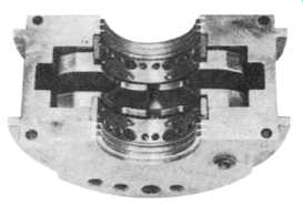
FIG. 35 Double-acting segmented thrust bearing. (Siemens Energy and Automation,
Inc., Medium Power Generation Division, Bradenton, FL.)
The journal bearings are of the multiwedge type. They are white-metal lined.
The oil-film wedges uniformly spaced around the circumference hold the rotor in a stable position.
The position of the bearing housings in the pedestals can be adjusted with alignment devices to align the rotor accurately. This alignment ensures that the correct radial clearance is obtained in the blading and labyrinth seals. The axial position of the rotor within the casing is determined by the thrust bearing in the front beating housing. It’s of the double-acting segmented type ( FIG. 35). The bearing segments are also lined with white metal.
As its temperature rises, the rotor expands in the direction of the exhaust hood.
Since the casing is fixed at the rear bearing housing, the front beating housing carrying the thrust bearing expands in the opposite direction. Hence, only the very much smaller differential expansion between rotor and casing is temporarily effective. The thrust bearing accepts any residual thrust that has not been eliminated by the balance piston.
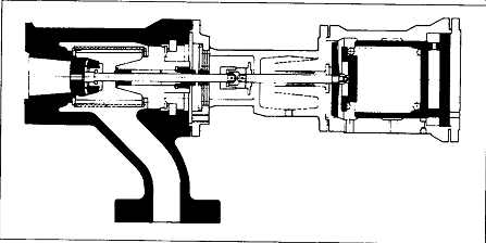
FIG. 36 Emergency stop valve incorporating a steam strainer. (Siemens Energy
and Automation, Inc., Medium Power Generation Division, Bradenton, FL.)
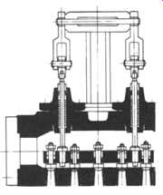
FIG. 37 Steam turbine control valves. (Siemens Energy and Automation, Inc.,
Medium Power Generation Division, Bradenton, FL.)
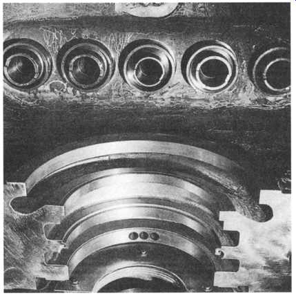
FIG. 38 Valve diffusors and L-section sealing rings in the top half casing.
(Siemens Energy and Automation, Inc., Medium Power Generation Division, Bradenton,
FL.)
Valves and Governing System
The initial steam is admitted to the admission chest through the emergency stop valve ( FIG. 36). During normal operation, this valve is held open against spring load by hydraulic pressure. In the event of a defect, the trip oil circuit is vented and the springs close the valve in a fraction of a second.
A steam strainer is incorporated in the valve body. It’s comprised of corrugated steel strip wound spirally on edge on a former. In comparison with the perforated type of strainer, the wound type is considerably stronger, has a greater flow area and a smaller aperture size.
The nozzle control system of standard turbines makes extensive use of lever mechanisms. The five nozzle control valves are suspended from a beam ( FIG. 37). The beam is raised and lowered on two spindles through a system of levers by a front-mounted hydraulic servomotor. This arrangement means that there are only two spindle glands in the admission chest. Both spindles move whenever there is any control action so that the possibility of seizure is virtually eliminated.
The distance between the top of the adjusting bushing in the beam and the underside of the backing nut at the top of the valve spindle varies from valve to valve. Thus when the beam is lifted, the valves open in sequence, allowing steam to reach individual nozzle segments progressively. The valve diffusors in the top half of the casing are shown in FIG. 38.
+++ +++ SUB-SECTION 5A+++ +++
(Tables and Figures, coming soon!)
Steam Turbines: Some Design Theory Factors
There are many factors affecting overall blade performance. They should all be carefully weighed before a design is released for production. The discussion here will be limited to just two of these factors: frequency and stress analysis. We shall see how they can affect the final design of a blade.
ENGINEERING
Stress Analysis
The stress levels in each blade must often be given strong consideration. As explained later, stress is best evaluated by a modified Goodman diagram, which provides a ratio of allowable cyclic stress to the maximum steam bending stress.
This ratio should have certain minimum values for each stage under consideration.
There are many factors affecting the mechanical integrity of a blade. The damping of the stage, caused by the inherent damping qualities of the material, together with the method of attaching the blades to the disk, is one. Disk configuration and the type of shrouding are other factors.
A Campbell diagram, described below, is merely another one of the tools for designing blades. It cannot alone determine if a blade will operate reliably.
Blade Frequency:
The simplest method for blade frequency analysis has been to use the natural frequencies of individual blades. This can be misleading because blades vibrate differently in assembled packets.
Individual blade frequencies are easy to obtain. However, static packet testing will yield more complete data. Dynamic packet testing is clearly the most accurate method, but it has been and always will be extremely expensive.
The most widely-used frequency consideration is the Campbell diagram. Mr. Campbell experimented with disk frequencies back in the early days of steam turbines. There were numerous disk failures then, caused primarily by disk resonance at wheel critical speeds.
The industry has since coined the name "Campbell diagram" to mean "interference diagram." These are useful in showing when natural blade frequencies coincide, or interfere, with various operating harmonics such as multiples of running speed or nozzle passing frequencies (NPF). Many engineers feel that if any interference exists, the blade will fail- but is this true? Experience indicates it’s almost impossible to design a multistage turbine with no interference. The turbine must therefore be designed to operate reliably in certain modes of resonance.
(coming soon) FIG. A-1 Campbell diagram for an individual steam turbine blade. (Elliott Group, Jeannette, PA.)
(coming soon) FIG. A-2 Campbell diagram for an eight-blade "packet"
Example:
To prove the point that frequency is not the only factor to consider in the design of a turbine blade, let's review a blade in terms of frequency and stress. The example is an 0.847-inch (21.5-mm) blade on an 18-inch (460-mm) diameter.
The first Campbell diagram, FIG. A-l, shows no interference of the fundamental tangential mode with NPF. Keep in mind that these data are based on individual blades. Realize, also, that the various "modes" simply describe vibration behavior in different directions or at multiples of a fundamental vibratory frequency.
The second interference diagram, FIG. A-2, is on the basis of static packet data and the situation worsens; the fundamental axial mode intersects the NPF. (Packets describe several blades joined by a shroud band or similar means.) Centrifugal force will tend to increase the natural frequencies, but this particular blade will still be operating in resonance. The conclusion might be that this blade will fail. This is not necessarily so. The stress in the blade has not been considered, and it’s a fact that failure occurs only when the operating stress exceeds the endurance limit, regardless of what causes the stress.
(coming soon) FIG. A-3 Modified Goodman diagram used for blade stress evaluation. (Elliott Group, Jeannette, PA.)
FIG. A-4 Data used in modified Goodman diagram. (Elliott Group, Jeannette, PA. )
(coming soon) FIG. A-5 Approximate efficiency chart for steam turbines. (Elliott Group, Jeannette, PA.)
Modified Goodman Diagrams
Many experienced manufacturers rely on a modified Goodman diagram for stress evaluation. For the ultimate stress, the strength of the blade material at the design operating temperature is used. The endurance limit used is based on the corrected ultimate stress and other considerations such as the fatigue notch factor. A straight line is then constructed between the ultimate stress and the corrected endurance limit.
Theory states that failure will occur when the total stress in the material is to the fight of the failure line. The steady state stress is the sum of the centrifugal stress and steam bending stress. This total steady state stress is plotted on the abscissa.
A straight horizontal line is then drawn over to the failure line, a vertical line is constructed, and this becomes the allowable alternating stress. This is shown in FIG. A-3.
The allowable alternating stress, divided by the steam bending stress, is the Goodman factor. In theory, the steady state stress can equal the ultimate stress, without failure, when the alternating stress is zero. Further, the alternating stress can equal the corrected endurance limit, without failure, when the steady state stress is zero. Blade reliability is thus seen to be a combination of steady state stresses and alternating stresses.
Past operating history has established safe, minimum Goodman factors. The blade in question has a 25.8 Goodman factor, as indicated in FIG. A-4. This is well above the minimum requirements for this stage. Many manufacturers would feel safe in recommending it for this application even though a Campbell diagram shows frequency interference. They can support their recommendation by showing that this stage has been in actual operation, with both the fundamental tangential and axial modes at nozzle passing frequency, for many years. The example adds emphasis to what was said at the beginning: many factors affect reliability, and it behooves the designer to look at all of them.
Steam Consumption (Approximate Steam Rates)
FIG. A-5 and Table A.1 can be used to determine an approximate turbine efficiency when horsepower, speed, and steam conditions are known. In many instances, an approximate efficiency may well serve your purpose, since the parameters mentioned may change.
As can be seen in the example, a 25,000 HP, 5000 r/min turbine using steam at 600 psi/750~ Hg abs. has an approximate efficiency of 77 percent.
Applying this approximate efficiency to the theoretical steam rate (TSR) results in a steam rate and steam flow as follows:
TSR 600 psi/750~ Hg abs. = 7.64 lb/kwhr
TABLE A.1 Theoretical Steam Rates (lbs/kwhr)*
(coming soon) FIG. A-6 Part-load-speed correction curves.
From the curve, the HP correction is 1.04 and the r/min correction 1.05.
Total correction is 1.04 x 1.05 - 1.09.
The part-load steam rate is therefore 7.40 x 1.09 = 8.06 lb/HP-hr.
TURBINE SELECTION: DESIGN FACTORS
Staging, Pressures, and Temperatures
The following examples illustrate the performance of various combinations of impulse staging. It should be understood, of course, that stage selection and overall turbine efficiency are affected by many important considerations other than stage efficiency. Speed limitations, mechanical stresses, leakage and throttling losses, windage, bearing friction, and reheat- all these must be factored into the ultimate turbine design. That's the job of the factory specialist.
The approximate efficiencies of a Curtis stage and a Rateau stage are shown in FIG. A-7.
Basic Formulae
(Refer to Table 5A.2 for English to metric conversions.) zrDN
Vb = 720 Vj = 224v/h~ -h2 = 224~/AH
where Vb = Pitch line (blade) velocity, ft/s
D = Pitch diameter of wheel, inches (base diameter plus height of blade)
N = Rotative speed, r/min Vj = Steam jet velocity, ft/s hi = Inlet steam enthalpy, Btu/lb h2 -- Isentropic exhaust steam enthalpy, Btu/lb h2e "- Stage exit steam enthalpy, Btu/lb AH = Isentropic heat drop, Btu/lb (h] -h2)
Vb/Vj = Velocity ratio, dimensionless
(coming soon) FIG. A-7 Velocity ratio versus efficiency. (Elliott Group, Jeannette, PA.)
(coming soon) TABLE A.2 English-Metric Conversion Table
(coming soon) FIG. A-8 Entropy versus enthalpy chart For example 1. (Elliott Group, Jeannette, PA.)
(coming soon) FIG. A-9 Entropy versus enthalpy chart For example 2. (Elliott Group, Jeannette, PA. )
(coming soon) FIG. A-10 Entropy versus enthalpy chart For example 3. (Elliott Group, Jeannette, PA. )
Find the number of 35-in diameter Rateau stages required, assuming optimum stage efficiency (see FIG. A-l 0).
From Mollier chart, the isentropic heat available is: 1305.7- 1184.2- 121.5 Btu/lb
Alternatively, using a TSR table or Polar Mollier chart: TSR- 28.08 lb/kwhr
FIG. A-12 Performance map for typical extraction turbine. (Elliott Group, Jeannette, PA.)
EXTRACTION TURBINE PERFORMANCE
Today's fuel costs demand that the maximum amount of energy be squeezed from each pound of steam generated. To help in this effort, when both process steam and shaft power are required, many plant designers are turning to extraction turbines.
The extraction turbine can substantially reduce the energy charged to the driven machine if process steam would otherwise be supplied through pressure-reducing valves. Even though back-pressure turbines can be used to supply process steam, they are rather inflexible, since the shaft power and process steam requirements must be closely matched. An extraction turbine, however, can cope with changes in these variables and satisfy the requirements of each over a broad range.
The diagram in FIG. A-12 shows the performance map for a typical extraction turbine. Determining the shape of this diagram is a problem that often arises. Here is an example that demonstrates the procedure to follow in drawing an approximate extraction diagram.
Selecting a turbine to complement a particular steam balance is made easier, however, by the wide variety of turbines available. Condensing, back-pressure, or extraction/induction turbines can be used, as required, in designing both new plants and additions to existing plants.
Steam for process use, For example, can be supplied from the exhaust of a back-pressure turbine or from an extraction turbine. The choice would depend on the number of pressure levels involved, the design of the remainder of the plant, the number of turbines required, etc. This versatility simplifies the job of optimizing a steam balance.
The steam balance diagrams shown in Figs. A-13 through A-15 illustrate how various types of turbines have been used to supply both shaft horsepower and steam for other uses.
FIG. A-13 Steam balance, Example 1. Steam is extracted from turbine A at 400 psig, and steam is extracted from turbine B at 225 psig. (Elliott Group, Jeannette, PA.)
FIG. A-14 Steam balance, Example 2. Three turbines all use steam from the 900psig/850~ (62 bar/4550C) boiler. Steam is extracted from both larger units at 410 psig (28.3 bar)for process I, and the remainder is condensed at 4 in Hg abs. (135 mbar). Smaller back-pressure turbine exhausts steam at 190 psig (13.1 bar)for use in process II. (Elliott Group, Jeannette, PA.)
FIG. A-15 Steam balance, Example 3. Topping turbine concept was used in this plant, where exhaust from a high-pressure turbine as well as the low-pressure turbines is used to supply process demands. Exhaust steam from these low-pressure units is then condensed at 3.5 in Hg abs. (120 mbar). (The Elliott .Company, Jeannette, PA. )
We note from FIG. A-13 that two 1500 psig/950~ turbines drive the large compressors in this application. Two different extraction pressures were used (400 psig and 255 psig), with lower pressure steam being supplied to a process and to the smaller turbine. Exhaust steam from all three turbines is then condensed at 4 in Hg abs.
+++++ SUB-SECTION B +++++
(Tables and Figures, coming soon!)
Selecting and Sizing a Steam Turbine
There are three main Steam Turbine model types (generic model letters and numbers in this Sub-section refer to the contributing source's model designation).
(1) High-pressure backpressure turbine type KR R6 after Kanisder;
(2) Backpressure turbine type G
(3) Condensing turbine type V.
The turbines of these model ranges are not only used as single-casing machines for driving generators and driven machines but, by combining several turbines, can also be employed as dual- and triple-casing steam turbosets. Our standard design includes the possibility of coupling other machinery on either end of the turbines. The turbosets can be equipped with reheating systems, multiple feedwater heaters and various extraction points. Secondary steam admissions are also possible by standard.
BACKPRESSURE TURBINE TYPE G (TABLE B.2 AND FIG. B-1)
The backpressure turbine type range G, comprising eight model sizes, covers an output range from 1 to over 100 MW. With the exception of the largest type G80, all the maximum type speeds of the standard program are higher than those of the two-pole alternators and the smallest type attains a speed of 16,000 RPM. Since it’s quite normal nowadays to use gear units to transmit outputs of up to approx. 40 MW, a direct alternator drive is also available only from type G40 onwards. The maximum live steam conditions of the standard model comply with the values normally used in industry today.
The maximum casing backpressure for continuous operation lies at 16 bar. At backpressures of 6 bar and above, leakage steam is extracted from the shaft labyrinth glands.
The type designation relates to the nominal diameter of the blading in cm. The product of blading diameter and maximum type speeds is fairly constant for all sizes, and all types are similar.
The maximum inlet volume via the nozzles is limited by the possible nozzle cross-sectional area at maximum type speed.
The maximum inlet volume via the bypass is dictated by the cross-section available in the valve chest.
The maximum outlet volume is determined by the permissible steam velocity in the exhaust nozzle, the velocity being lower with higher pressures.
In cases where the operating conditions differ from the standard design parameters, such as higher backpressures, larger. (ABB Turbinen GmbH, Nurnberg, Germany volumes at the turbine inlet, and higher speeds or outputs, it would be necessary to consult the design engineers.
Description and Dimensions, Type G ( Figures B-2, B-3 and Table B.3)
The backpressure turbines of the type range G are designed as multistage reaction turbines with approx. 50 percent reaction. A single-row or, with direct alternator drivers, also a double-row flow-controlled impulse control wheel is provided upstream of the reaction section that is always fitted with shrouded blading. The guide blades are mounted in thermo-elastic guide-blade carriers which are suspended centrally in the casing. The nozzle chests for steam admission to the control wheel are assembled separately in the upper and, when necessary, in the lower part of the casing and welded in position. They are connected to the valve block, arranged above the main casing in most cases, by means of welding nozzles and piping.
The horizontally divided turbine casing is of simple and fully symmetrical construction. It serves only to guide the steam pressure and to accommodate the guide-blade carrier and the labyrinths. It’s symmetrically supported on the two bearing housings. Radial bolts serve to avoid a displacement of the casing center line with regard to the bearing center and thus to the rotor axis under all operating conditions. The turbine rotor, manufactured from one single forging, is guided axially in the front bearing housing. The rear bearing housing is usually designed as the fixed point, so that the exhaust-side shaft end is subjected only to minimal axial movement at startup.
CONDENSING TURBINES TYPE V (TABLE B.4 AND FIG. B-4)
The condensing turbine type range V consists of eight model sizes and covers an output range from 1 to over 100 MW. With the exception of the largest type V90, the maximum type speed is higher than that of the two-pole alternators and the smallest turbine attains a speed of 14,000 RPM. Since it’s quite normal nowadays to use gear units to transmit outputs of up to 40 MW, direct alternator drive is only provided for from type V50 upwards. The maximum live steam conditions are comparable with those of the backpressure turbines of similar size.
The exhaust casings are designed for backpressures of less than 1 bar, but will withstand short-time atmospheric exhaust operation in case of a failure of the evacuating equipment, For example.
The type designation corresponds to the nominal diameter of the high-pressure blading up to type V32, and from type V40 upwards to the mean value of the HP and LP blading diameters. All types are of similar thermodynamic design.
The maximum inlet volumes via the nozzles are limited by the nozzle cross-sectional areas available at maximum type speed, whereas the bypass inlet volumes are determined by the maximum steam velocity in the valve chest.
In cases where the operating conditions differ from the standard design parameters, such as higher live steam pressures and temperatures, larger inlet volumes, or higher outputs and speeds, it would be necessary to consult the design engineers.
TABLE B.1 Multistage Steam Turbines
Description and Dimensions, Type V ( Figures B-5, B-6 and Table B.5)
Fig. B-1 Selection diagram for backpressure turbines type G (approximate values).
The condensing turbines, type range V, are designed as multistage reaction turbines with approx. 50 percent reaction.
A single-row or double-row flow-controlled impulse wheel is incorporated ahead of the shrouded HP blading. The LP blading, not equipped with shrouding on account of the centrifugal forces, is usually fitted with damping wire. All guide-blade rows are mounted in carriers which are centrally suspended in the turbine casing. The nozzle chests for steam admission to the control wheel are welded into the upper and, where necessary, also the lower part of the casing. They are connected to the valve block above the main casing with welding nozzles and pipes. The horizontally split turbine casing is of symmetrical construction. The exhaust casing of welded steel is vertically flanged on.
Symmetrically to its center line the turbine casing rests on two lateral supports on the exhaust casing and on the front bearing housing. By means of radial bolting with the latter a displacement of the casing center line from the bearing and rotor centers is avoided at all operating conditions. The turbine rotor, machined from one single forging, is guided axially in the front bearing housing. The exhaust flange support serves as fixed point of the machine. The turbine casings can be combined with various exhaust casing sizes depending on the exhaust volumes.
Several standard blade-row combinations are available for the condensing section to optimally adapt the turbine to the given speeds and vacuum conditions.
Fig. B-2 Standard backpressure turbine type G, longitudinal cross-section. (ABB , Germany)
Fig. B-3 External dimensions, backpressure turbine type G. (ABB , Germany)
The Building-Block System
The design of a steam turbine is dictated by many parameters (steam conditions, steam flow, output, speed). There- fore turbine models are required that-with a minimum of expenditure and technical effort- can be largely adapted to the operating conditions of the individual turbine user.
We use a building-block system which fulfills the demand for economic production and highly developed, reliable components. The live steam valve blocks are standardized as to their nominal diameter and pressure and are combined with the different turbine casings of the individual type ranges.
Dependent on the live steam conditions and steam flow, the steam is admitted to the casing either from the top ( FIG. B-7) or from top and bottom ( FIG. B-10). The length of the bladed section in the standard turbine casings is so selected that at each type speed and with the statistically most frequent heat drop through the turbine optimal efficiency is obtained. In the event of lower speeds (e.g. compressor drivers) or larger heat drops, the length of the bladed section and consequently the number of stages can be increased by lengthening the turbine casing in steps as shown in Figs. B-9 and B-11. in the case of backpressure turbines up to four extension rings can be incorporated into the normal standard model. The turbine models are in addition sized according to their pressure rating. The exhaust flanges can either be welded to the top or to the bottom of the fully symmetrical backpressure casing.
Flg. B-4 Selection diagram for condensing turbines type V, size 1 (approximate values) (ABB , Germany)
Fig. B-5 Standard condensing turbine type V, longitudinal cross-section. (ABB , Germany)
The condensing turbine range is designed in the same manner and follows the same principle as the back-pressure turbine range (valve block and casing systems). The length of the bladed section can be increased in the high-pressure casing by incorporating extension rings, and in the low- pressure casing by using a longer and wider size of the welded rectangular exhaust casing ( FIG. B-9). Several exhaust casing sizes, each suitable for different vacuum conditions, can be supplied. Various last-row blade heights or blading cross sections are available for each exhaust nozzle.
The exhaust casings can be oriented in upward direction, if required.
Owing to the standard modules, the condensing turbines can also easily be designed as double-flow machines (type V ... Z, FIG. B-12). Thus it’s possible to double the exhaust volume capacity at a given type speed, which is frequently of great advantage to the mechanical drive of high-speed compressors and pumps.
The standard bearing housings are used for both the G and V type turbines as well as for other type ranges. Each bearing housing size can be used for several turbine sizes. The exhaust-end bearing housings of the backpressure turbines also serve as front bearing housings, when the machine is used as a two-end driver or does not require a pump or governor drive.
Fig. B-6 External dimensions, condensing turbine type V. (ABB , Germany)
Extraction Turbines
Turbines of the type ranges G and V can also be supplied with controlled extractions (types GE and VE). Through these extractions steam can be taken from the turbine at a given controllable pressure and be made available to other consumers.
Since the distribution of the heat drop in the turbine ahead of the extraction point (HP section) and after it (LP section) may vary greatly depending on the pressure relationships p~, PE, P2 (live steam pressure, extraction pressure, backpressure), the extraction point must be located at different positions in the casing (Table B.6). The extraction point rating depends on the extraction pres- sure and on the maximum extraction volume which should not exceed about 45 percent or 20 percent of the maximum type exhaust volume for backpressure turbines or condensing turbines respectively.
The maximum possible exhaust steam flow and the maximum live steam flow are dictated by the maximum inlet and out- let volumes of the individual machine type (see Tables B.2 and B.4). The standard modules for steam extraction are fitted in the place of the extension rings (Figures B-9 and B-11) or, with alternatives 2 and 6 (Table B.6), ahead of the guide-blade carrier support.
These standard modules for steam extraction incorporate either nozzle-group segments for a subsequent control wheel (alternatives 1,2,3 and 5, Table 5B.6) or include the throttle control elements for the low-pressure section (alternatives 4, 6 and 7). The extraction control valves can be arranged in the upper or lower casing or in both casing halves. They are actuated by laterally arranged hydraulic servomotors that are isolated from the hot parts ( FIG. B-17).
Fig. B-7 Casing cross-section with upper nozzle chest arrangement. (ABB Turbinen GmbH, Germany)
Fig. B-8 Basic building-block concept of a backpressure turbine casing. (ABB , Germany)
DOUBLE-EXTRACTION TURBINES
Larger single-casing turbines may also be equipped with two controlled extraction points ( FIG. B-18), if a second network is to be supplied with pressure-controlled steam.
BLEED TURBINES
Bleed points on turbines permit the uncontrolled extraction of steam. They are mostly provided for the supply of feedwater heaters, for the single or multistage heating of the turbine condensate, or for smaller steam consumers where variations in pressure are permissible or where the throttling losses of the succeeding reducing valves may be neglected. The bleed pressure depends on the location of the bleed point in the blading section and on the machine load or on the onflowing steam quantity, and will drop to almost backpressure level under no-load conditions. The maximum pressure is reached at full load ( FIG. B-19). If, however, a network is to be supplied with constant pres- sure, it’s possible to provide several bleed points in the blading section and to open only that point with the help of an automatically operating pressure-dependent bleed point selection station, at which the least pressure drop between the bleed pressure in the casing and the required system pressure exists ( FIG. B-20).
Fig. B-9 Condensing turbine casing in building blocks with line extension ring in the HP section and two exhaust sizes.
(ABB Germany)
Fig. B-10 Cross-section of casing, nozzle chests arranged above and below. (ABB , Germany)
Fig. B-11 Backpressure turbine casing in building blocks with two extension rings. (ABB Turbinen GmbH, Nurnberg, Germany)
TABLE B.6 Standard Alternatives for the Location of the Extraction Modules
Fig. B-12 Double-flow condensing turbine type V .. Z with two upward exhaust nozzles. (ABB Turbinen GmbH, Nurnberg, Germany)
CONTROL VALVES
To obtain good steam consumptions at partial loads, the turbines are designed with flow control. Based on their long experience ABB have developed a consecutive compound control valve system ( FIG. B-21) incorporating very few and well-protected moving parts, which ensures reliable steam flow control. Only one spindle passage must be sealed with a gland bush.
The control valves are housed in tubular cast-steel casings that are most suited for high-pressure steam. Up to three of these casings are welded together in one block, dependent on the number of valves required. The wall thickness of the casings is selected in accordance with the nominal pressure.
The emergency trip valve is located at one end of the valve block, the hydraulic valve actuator at the other.
When loading the turbine, valve one is first actuated by the driving rod of the main cylinder. When the first valve is fully open, the clearance to the second valve is covered and valve two starts to open. Then follows the third valve. If more valves are required for the control of the turbine, or if a second emergency trip valve is to be provided, additional valve blocks can be arranged on top of the turbine casing and connected to it by means of pipes ( FIG. B-26). Each valve spindle is supported at both ends with a short bearing span to avoid hazardous spindle breakage. The spindles are protected from torsion. The withdrawable valve cages are so designed that their resistance to steam flow is minimal. The valve internals are manufactured from high quality chromium-nickel steel. Valve seats and passages are hardened, the valve spindles are nitrided, and the springs, which are isolated from the steam, are made of nimonic nickel alloy or stainless spring steel. The valve actuator, arranged separately from the hot valve block ( FIG. B-21 ) is operated by pressurized oil via the oil relay. The impulse pressure P3 from the speed governor opens the inlet Pl when the turbine load is increased, or the outlet P0 when the load is gradually reduced. In case of a sudden load drop the patented quick- closing device at the bottom of the servomotor is opened by means of a second control edge so that the oil flows off and the valves are closed very quickly ( FIG. B-25). Thus the machine is prevented from reaching overspeed even in the event of a full load throw-off.
Fig. B-13 Double-flow condensing turbine type V50Z for driving a feed-water pump. (ABB Turbinen GmbH, N0rnberg, Germany)
Fig. B-14 Extraction diagram. (ABB , Germany)
Fig. B-15 Backpressure turbine with extraction - In building blocks. (ABB , Germany)
Fig. B-16 Flow diagram o an extraction-back-pressure-turbine. (ABB , Germany)
Fig. B-17 Arrangement of extraction valves. (ABB , Germany)
Fig. B-18 Double-extraction backpressure turbine for 35,100 kW, live steam conditions 117 bar/517 ~ backpressure 6 bar, with a first extraction at 46 bar and a second extraction at 21 bar. (ABB Turbinen GmbH, Nurnberg, Germany)
Fig. B-19 Bleed pressure diagram of a pressure-dependent extraction system. (ABB , Germany)
Fig. B-20 Pressure-dependent extraction system with pressure control station. (ABB Turbinen GmbH, Nurnberg, Germany)
Fig. B-21 Conaecutive compound control valve block with valve actuator. (ABB , Germany)
Fig. B-22 Hydraulic valve actuator with a relay. (ABB , Germany)
Fig. B-23 Backpressure turboset with control valve block and a fourth bypass valve. (ABB Turblnen GmbH Nurnberg, Germany)
Fig. B-24 Component parts of the consecutive compound control valve block. (ABB , Germany)
Fig. B-25 Velocity diagram of the valve actuator. (ABB Turbinen GmbH, Nurnberg, Germany)
Fig. B-26 Heating turbine with two control valve blocks and the corresponding emergency trip valves located ahead. (ABB Turbinen GmbH, Nurnberg, Germany)