AMAZON multi-meters discounts AMAZON oscilloscope discounts
Gas engines are internal combustion engines and incorporate many of the operating principles of modem automobile engines. They are reciprocating machines and come in a variety of sizes and configurations.
Gas engines, as the term implies, operate on gaseous fuel that is ignited by an electric spark. Smaller gas engines, typically in the 200- to 400-kilowatt (kw) range, are frequently used to drive emergency generators or fire water pumps. Integral gas engines, with compressor cylinders mounted on the engine crankcase ( FIG. 1), are often found in the larger size ranges, up to several thousand kilowatts of power output.
Again analogous to automotive engines, reciprocating gas engines are manufactured either as two-stroke-per-cycle or four-stroke-per-cycle machines. With twice as many power strokes per revolution, the two-stroke-per-cycle engines tend to be smaller than four-stroke-per-cycle versions built for the source power output. Moreover, the two-stroke machine is generally less complex because it can dispense with valves and their associated mechanisms.
Reciprocating gas engines display typical efficiencies in the 28 to 42 percent range. The upper portion of this range belongs to turbocharged engines, whereas the lower range is populated by naturally aspirated machines.
Turbocharged equipment uses exhaust gas to drive a blower that forces combustion air through a suitable heat exchanger into the intake manifold. This cooled, compressed air is used for combustion and, in certain engine types, "scavenging." Scavenging air purges exhaust gases from engine cylinders before combustion air is admitted.
Reciprocating gas engines suffer from a few disadvantages that must be considered when selecting process plant equipment:
++ They require a fair amount of competent surveillance and routine maintenance.
Minor overhauls are typically needed after about 2500 operating hours. Major overhauls should be anticipated every three to five years.
++ Their low speed, typically in the 180 to 900 RPM range, requires step-up gears for such process duties as pump drives.
++ Fluctuations in the heating value of the fuel may require constant adjustment of spark timing and could also require derating of the power output capability.
++ The sulfur content of gas engine fuels may adversely influence the extent and frequency of maintenance required.
Gas engines typically consume between 6500 and 8000 British thermal units (Btu)/brake horsepower (BHP)-hour.
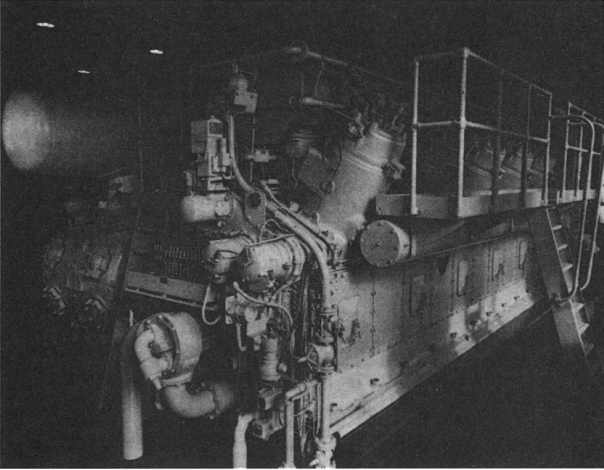
FIG. 1 Large gas engine (ten cylinders) with built-on reciprocating compressor
cylinders. (Cooper-Bessemer Reciprocating, Grove City, PA)
TWO-STROKE GAS ENGINES
It could be stated that gas engines are basically blown-up versions of the conventional automotive engine with just a few important modifications" they are slow-running, they use a gaseous fuel/air mixture instead of the liquid fuel/air mixture typically found in most automotive engines, and they are often integrally arranged (or combined) with the process gas compressor cylinders that they are driving.
Since the combustion process takes place inside the cylinder, gas engines belong to the family of internal combustion engines. Like their cousins the automotive gasoline and automotive diesel engines, gas engines are either of the two-stroke or of the four-stroke per cycle variety. Two-stroke engines have one power stroke for every full revolution of the crankshaft, whereas in four-stroke engines, only every second revolution is accompanied by a power stroke. Four-stroke engines have inlet and exhaust valves; two-stroke engines have inlet and exhaust ports.
Each type of engine has a spark plug; the two-stroke engine also incorporates a fuel admission valve.
With two-stroke engines considerably more prevalent in the process industries, we will confine our considerations to this type of engine.
Modem units are typically con figured as shown in FIG. 2. This cutaway view illustrates a Cooper-Bessemer model GMVH, essentially a combination V-type gas engine and horizontal compressor built into one compact unit. The typical two- stroke engine is built in units of six, eight, ten, and twelve cylinders; the number of compressor cylinders varies according to requirements and arrangements yield any combination of volume and pressure within the rating of the engine.
The GMVH is a two-stroke-cycle loop-scavenged V-type engine, designed to use natural gas as a fuel. Scavenging air is supplied by an exhaust-driven turbocharger and a highly developed control system maintains optimum combustion under varying conditions of load and speed. Perhaps the best way to study this engine is to review its principal components identified in FIG. 3.
The engine base ( FIG. 3, item 17) is a complex iron casting that forms the backbone of the entire structure. The main journal beatings are vertically split, leaving one side of the base open for easy access to the bearings and the crankshaft.
Once the alignment and fit of the main bearings have been established, the caps and outer shells are removed and the crankshaft ( FIG. 4, item 24) is installed.
The bearing halves and caps are then installed and properly tightened once more.
The crankshaft is a high-quality steel forging, machined with great precision and having a very fine finish on all bearing surfaces and fillets. Oil holes are drilled from the main journals to the adjacent crank pins to transmit large quantities of lubricating oil from the pressure-fed main beatings for lubrication of the connecting rod beatings and cooling of the power pistons.
The remaining connecting rod assembly depicted in FIG. 4 is installed next.
The main connecting rod, item 7, is used to drive the compressor piston. The power connecting rods, item 11, are articulated to the main connecting rod in a manner similar to that used in radial aircraft engines. In an engine of this type, the load on the power connecting rod is always compressive.
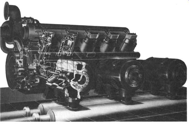
FIG. 2 Cutaway view of a modern gas engine reciprocating compressor combination.
(Cooper-Bessemer Reciprocating, Grove City, PA)
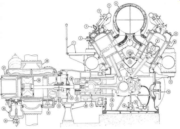
FIG. 3 Cross-section of a Cooper-Bessemer-type GMVH gas engine compressor.
1-platform and railing; 2-jet cell igniter; 3- gas injection valve; 4- load
balancing valve; 5-jacket water outlet header; 6- insulated exhaust manifold;
7-jacket water inlet header; 8- power cylinder head; 9- power piston; 10-power
cylinder; 11-air inlet manifold and intercooler; 12-layshaft; 13-articulated
power rods; 14 - crankcase relief valve; 15 - lube oil pressure regulator;
16- lube oil suction header; 17- engine base (crankcase); 18-master rod;
19-crosshead and shoe; 20-crosshead guide housing and support; 21-crosshead
balance weights; 22-crosshead diaphragm and packing; 23-compressor cylinder
rod packing; 24 - valve cap; 25 - plug-type suction valve unloader; 26 -
unloader volume bottle; 27 - compressor cylinder head; 28- compressor cylinder
body; 29-compressor piston; 30-piston rod and nut. (Cooper-Bessemer Reciprocating,
Grove City, PA)
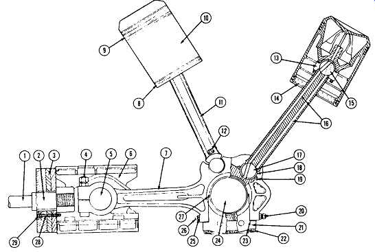
FIG. 4 Gas engine reciprocating compressor crankshaft assembly showing
power pistons and compressor crosshead. (Cooper-Bessemer Reciprocating, Grove
City, PA)
The power cylinders ( FIG. 3, item 10) are next mounted on top of the base.
The cylinder is a high-strength iron casting of some complexity, and FIG. 3, item 10 shows clearly the air induction ports as well as the higher exhaust ports and the passages leading to each. The self-contained jacket, providing a flow of cooling water, is also shown. The bore of the power cylinder is chrome plated and then honed to a high degree of precision. It’s common for such cylinders to be in continuous operation for several years without significant wear of the cylinder bore.
The power piston ( FIG. 3), item 9) is an oil-cooled trunk-type piston using four compression tings and two oil control rings. FIG. 4 shows these ring grooves as items 9 and 8, respectively. The piston pin housing, FIG. 4, item 13, is a separate casting, bolted into the piston, containing the bronze bushing for the pin at the upper end of the power connecting rod. The space between the pin housing and the piston crown receives a continuous flow of lubricating oil for cooling. This oil comes through a longitudinal drilled hole in one flange of the power connecting rod and up through one of the vertical tubes in the pin housing. Oil is continually drained through the other tube and down through the other side of the connecting rod. This cooling prevents excessive thermal strains in the piston even though the engine is operating at a high level of output. The cylinder head, ( FIG. 3, item 8) is an open-style iron casting with a cover plate to form a complete water jacket.
The fuel gas injection valve is located in the center of the head, and there are two spark plugs, one on either side of the gas valve.
The crosshead guide, ( FIG. 3 item 19), is now installed. This serves both as a mount for a compressor cylinder and as a stationary slide for the crosshead at the outer end of the main connecting rod. The crosshead, FIG. 4, item 6, has separate top and bottom shoes made either of aluminum or of cast iron with a babbitt overlay. These shoes are adjustable to fit with the proper clearance within the bore of the crosshead guide. The crosshead pin, item 5, is used to connect the crosshead to the eye in the outer end of the main connecting rod. The opposite side of the crosshead receives the end of the piston rod that drives the compressor piston.
The piston rod packing will be discussed in more detail later.
The last major component to be added to the basic mechanical structure is the flywheel. The flywheel is bolted and doweled to a flange on the end of the crankshaft.
Being of generous size, the flywheel serves to maintain the engine speed essentially constant, in spite of the variable turning effort of the power and compressor cylinders.
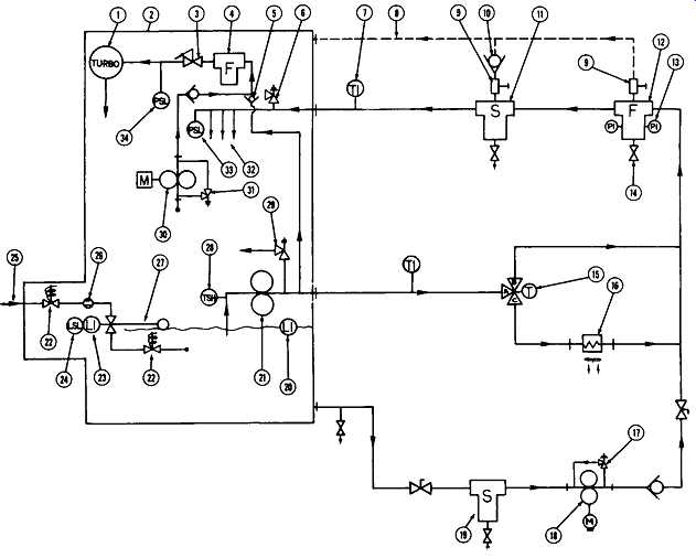
FIG. 5 Schematic representation of a gas engine pressure lube system. 1-
turbocharger; 2- engine outline; 3 - turbo oil variable pressure regulator;
4 - turbo oil filter; 5 - check valve; 6 - engine oil pressure relief valve;
7 - oil in temperature indicator; 8 -filter and strainer vent line; 9 - needle
valve; 10 - check valve; 11 - oil strainer; 12 - oil filter; 13 - differential
pressure gauge; 14 - drain valve; 15 - three-way thermostatic valve; 16 -
oil cooler; 17- pump relief valve; 18 - engine prepost-lube pump; 19 - oil
strainer; 20 - engine oil sight glass; 21 - engine main oil pump; 22 -fire
safe shut-off valve; 23 - oil level indicator; 24 - engine low oil level
alarm; 25 - oil supply to engine; 26-flow meter (optional); 27- oil level
regulator; 28 - engine high oil temperature shutdown; 29 - pump relief valve;
30 - turbo prepost-lube pump; 31 - pump relief valve; 32 - oil to engine
bearings; 33- engine low oil pressure shutdown; 34- turbo low oil pressure
shutdown. (Cooper-Bessemer Reciprocating, Grove City, PA)
Gas Engine Compressor Support Systems
Pressure lubrication is supplied to practically all lubrication points of the engine except the power and compressor cylinders, which are lubricated by a force-feed lubricator system. The external lubricating oil system will vary according to installation requirements. FIG. 5 is a schematic diagram of a typical system.
The wet-sump-type engine base serves as a reservoir for the lubricating oil. A sight gauge, located in the forward end cover, indicates the oil level at all times.
The pump suction header, in the bottom of the base, is perforated to form a strainer that prevents foreign matter from entering the pump. The oil pump (21) discharges the oil through an oil cooler (16), full flow filter (12), and strainer (11) and delivers it to the main oil header (32) in the engine base.
A thermostatic-operated three-way valve (15) is located in the system upstream of the cooler to direct oil through the cooler or around it to maintain the proper operating temperature. Thermometers should be installed in the line ahead of and after the oil cooler to give a constant reading of oil temperature.
From the lube oil distribution header, connections supply oil to all main bearings. From the main beatings, oil is delivered through drilled passages in the crankshaft to the master connecting rod bearings. The crankshaft ( FIG. 4, item 24) is drilled so that each master connecting rod receives oil from the two adjacent main bearings. From the master connecting rod, oil flows to the piston pin through a drilled passage in the articulated connecting rod. The crown of the power piston is jacketed, and oil from the piston pin is circulated through the jacket to cool the piston. Oil returns from the piston jacket through a second drilled passage in the articulated connecting rod, which connects with passages in the master connecting rod and is discharged to the base through holes in the master connecting rod cap.
Oil also flows through a drilled passage in the master connecting rod to lubricate the crosshead pin and guide.
Vertical oil lines at the flywheel end carry oil from the main header to all the chain sprockets and bearings. Oil is returned to the base by gravity. At the other end, lines carry oil under pressure to all auxiliary drive shaft beatings, gears, chains, etc.
A pressure relief valve, located at the flywheel end of the oil header inside the base, protects the system against excessive pressure. A pressure gauge on the control panel indicates the oil pressure in the system. To maintain the required oil level in the base, an automatic control valve is sometimes installed in an oil makeup line.
The filter consists of a housing or shell containing replaceable, yarn-wrapped elements operating in parallel to give the desired capacity. The frequency of replacing the elements will vary with operating conditions. As the elements become contaminated, the pressure drop across the filter will increase.
Modem machines have the main lube-oil header installed in the engine base.
High-pressure flexible lines supply oil from the header to the main bearing caps, from where it’s carried to the rest of the running gear as previously described.
The engine is equipped with either multiple pumps or a block distribution-type force-feed lubrication system. All force-feed lubricator systems are divided into two separate sections. One section supplies lubricant for the power cylinders while the other section supplies lubricant to the compressor cylinders. This arrangement permits the use of different oils to lubricate the compressor cylinders when required.
For certain types of compressor service, this is unnecessary and the same oil may be used for both power and compressor cylinders.
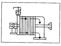
FIG. 6 Fuel piping system for two-stroke gas engine. 1 - engine gas header;
2 - load balance valve; 3-jet cell igniter; 4- gas injection valve; 5- cylinder
head; 6- pilot gas header to igniters; 10-regulator feedback line; 11- gas
pressure regulator; 12- starting pressure adjustment; 13 - speed signal inlet
pressure and gauge; 14 - gas inlet, psi maximum; 15-manual gas shut-off valve;
16-regulator pilot filter; 17-fuel gas command signal; 18 - gas pressure
gauge tap; 19 – igniter pilot gas filter and pressure gauges; 20 - gas supply
to pilot gas filter; 21- governor-operated gas regulating valve. (Cooper-Bessemer
Reciprocating, Grove City, PA)
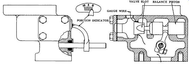
FIG. 7 Gas-regulating valve for modem gas engine. (Cooper-Bessemer Reciprocating,
Grove City, PA)
Fuel System
The fuel piping system ( FIG. 6) consists of a variable fuel gas pressure regulator, gas receiver, manual gas cock, safety shut-off and vent valve, gas accelerating valve, governor-operated gas regulating valve, gas injection valves, and isolating valves.
The variable fuel gas pressure regulator regulates the gas supply pressure according to the governor speed signal. The receiver (located as close to the engine as possible)
absorbs pulsations in the gas flow and ensures a more uniform gas pressure at the engine. The safety shut-off and vent valve will shut off the gas supply and vent the line to the engine if an abnormal operating condition occurs. The gas accelerating valve controls the amount of gas supplied to the engine by the governor-operated gas valve during starting.
The variable fuel gas pressure regulator is installed in the main fuel gas supply line upstream of the receiver. The gas pressure required at the engine will vary with the number of power cylinders and the heat content of the gas. In every case, the pressure should only be high enough to enable the engine to carry about 10 percent overload.
The gas regulating valve ( FIG. 7) is located in the gas inlet on the operating end. It’s controlled by the speed-regulating governor to regulate the amount of gas according to load requirements. Gas enters the valve body from the supply line connected to the bottom of the body, passes through the valve port, and enters the inlet header of the engine. The valve is of the ported type and is designed to give a very fine regulation of flow for minimum travel of the valve and governor. A balancing piston on the valve stem will equalize the gas pressure in both directions of travel.
These design features give close regulation of gas flow and ensure steady operation and close regulation of engine speed at all loads.
FIG. 8 illustrates the gas injection valve in cross section. Gas from the header is admitted to the injection valve through a cylinder-isolating plug valve.
This valve is normally wide open and is used to restrict the flow to the injection valve to obtain load balance for equal distribution of load to the power cylinders.
The injection valve has a conical surface that seats on the valve seat insert.
The valve is opened mechanically by a push rod and rocker arm operated by a cam attached to the crankshaft and is closed by the spring in the injection valve. Packing at the upper end of the gas valve stem prevents leakage of gas at this point.
The gas valve operating mechanism ( FIG. 9) consists of a rocker arm assembly, cam follower, and push rod with a hydraulic valve lifter. The rocker arm assembly is mounted on the cylinder head. An adjustable tappet is provided in the end of each rocker arm to adjust the hydraulic valve lifter. The cam follower is located in the engine base and is held in place by the push rod and crosshead bracket. Each follower consists of a crosshead and hardened steel roller that rides on a gas cam attached to the crankshaft. The push rod and hydraulic valve lifter assembly connects the rocker arm and cam follower. This assembly consists of a two-section push rod, the lower section being a tubular steel rod and adapter, with the hydraulic valve lifter installed in the lower end. A push rod guide supports the upper end of the lower section of the push rod at the point where it protrudes through the base. The upper section of the push rod is also tubular steel and is connected to the lower section by a ball pivot.
FIG. 8 Gas injection valve cross section.
(Cooper-Bessemer Reciprocating, Grove City, PA.)
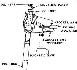
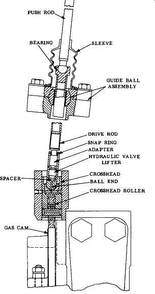
FIG. 9 Gas valve operating mechanism. (Cooper-Bessemer Reciprocating, Grove
City, PA.
FIG. 10 Typical jacket water cooling system for a gas engine. 1 - water outlet temperature; 2 - outline of engine; 3 - standpipe fill line; 4 - vent; 5 - standpipe overflow; 6- sightglass; 7- standpipe; 8 - drain; 9-jacket water cooler; 10- thermostatic valve; 11 -plug valve; 12- to intercooler water system (balance line); 13 - gate valve; 14 - pump flexible pipe connections; 15 -jacket water pump; 16 - to engine water inlet header; 17- turbo-charger; 18- engine water outlet header. (Cooper-Bessemer Reciprocating, Grove City, PA)
Cooling System
Cooling the engine is accomplished by two separate systems: the jacket water system, which circulates through the engine jackets and heat exchangers, and the aftercooler water system, which circulates through the heat exchanger, aftercoolers, and lube oil cooler.
One of the most important factors involved in the design of the cooling system is an adequate supply of clean water, free from sediment and scale forming ingredients, since even a very thin layer of scale or dirt on any heat transfer surface will act as an insulator, which may cause overheating and breakage. It’s preferable to circulate a large volume of water accompanied by a small temperature rise than to circulate a small volume of water accompanied by a large temperature rise. A large volume results in higher velocity through the system and retards the formation of scale and deposits of sediment in the jackets. Likewise, a low temperature rise means more uniform temperature at all points and less possibility of casting strains from this source. For these and other reasons, a closed cooling system is recommended.
In such a system, a minimum of makeup water is required. Therefore, treated water that removes scale-forming ingredients is not expensive.
There are numerous piping arrangements that can be used, and these will vary according to the number of engines installed, cooling equipment used, and other individual requirements. FIG. 10 is a typical diagram of the cooling system for an engine with a built-in jacket water pump and a motor-driven aftercooler water pump.
Tracing the flow of the jacket water system starting with the water pump, it’s directed to the cooling equipment. This may be a cooling tower, radiator, or any other type of suitable equipment. A three-way thermostatically operated proportioning valve is located ahead of the cooling equipment to maintain the proper jacket water inlet temperature to the engine by bypassing a portion or all of the water around the cooling equipment. The water flows from the cooler, or bypass, to the engine inlet header.
Cooling water enters the engine through the inlet header located in the vee of the engine between the two cylinder banks. From the header, water enters the bottom of the cylinder jacket and passes upward around the ports and enters the cylinder head jacket through outside jumper connections. Outlets from the cylinder heads connect with the water discharge headers. A jumper connects the two outlet headers at the flywheel end to give a common outlet connection. Turbocharger cooling water is supplied from the inlet header at the flywheel end of the engine, circulates through the turbocharger, and discharges into the engine outlet header.
From the outlet header, the jacket water flows to the standpipe where makeup water is added when necessary. From the standpipe, water returns to the suction of the jacket water pump where it’s again recirculated. The standpipe should be high enough to maintain a positive head at the suction of the pump. Its diameter should be large enough to limit the downward flow velocity to 0.5 feet per second, thus allowing any entrained air bubbles to rise to the surface.
All engines are equipped with two fin-tube-type aftercoolers. In some localities, additional cooling of the air may be required to enable the engine to carry rated load. Precooling is then recommended whereby the air is cooled before entering the turbocharger by passing it through an aquatower.
A separate cooling water system is required for the water circulated through the aftercoolers. Engine jacket water is not suitable, as the water inlet temperature should not exceed 120 ~ for proper cooling. Higher water inlet temperatures to the aftercoolers won’t cool the air sufficiently, and the engine will fail to carry rated load. Each aftercooler must receive ample cooling water for efficient operation.
Tracing the flow of the aftercooler water system ( FIG. 11), starting with the pump, water is discharged from the pump through the heat exchanger, the after-coolers, the lube oil cooler, and then back to the pump where it’s again recirculated.
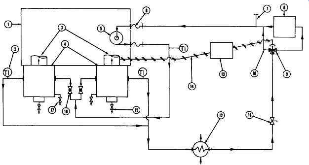
FIG. 11 Typical intercooler water system diagram for a gas engine. 1 -
outline of engine; 2 - intercooler water outlet temperature; 3- engine air
inlet manifold; 4- air intercoolers; 5- intercooler water pump; 6 - pump
flexible pipe connections; 7 - balance line (supply) from jacket water system;
8 - intercooler water cooler; 9-temperature control valve; 10-cooler bypass;
11-plug valve; 12- oil cooler; 13- temperature controller; 14 - temperature
control signal; 15 - intercooler vent; 16 - globe valve; 17 - intercooler
water drain. (Cooper-Bessemer Reciprocating, Grove City, PA)
The Power Train
Engines equipped with motor starting are cranked by air- or gas-driven reduction gear motors attached to a Bendix starter drive. Four- and six-cylinder engines have one starting motor; eight-, ten-, and twelve-cylinder engines have two. The pinion on the Bendix drive then engages the ring gear on the flywheel to crank the engine.
After the engine "fires," the starting valve is closed, pressure to the motors is shut off, and the Bendix drive pinion gear disengages the flywheel ring gear. Pressure to the starting motors is filtered and then lubricated by an oil-fog-type lubricator.
The layshaft is located in the vee between the power cylinders. It transmits power from the crankshaft to the auxiliary drive and is chain driven by the crankshaft at the flywheel end. The shaft is constructed in two sections and supported at both ends and in the middle by bronze beatings ( FIG. 12, items 1, 22, 32). It’s enclosed throughout its length by a tubular housing that is oil- and dust-tight. The layshaft chain tightener is located in the engine base at the flywheel end.
The main speed control governor, lubricators, and ignition timer are mounted on the auxiliary end drive cover and are driven by the layshaft. The governor is driven directly off the end of the layshaft and the timer is chain driven from the layshaft. The lubricators are chain driven from the timer drive. The positioning of these components is seen in FIG. 1, foreground.
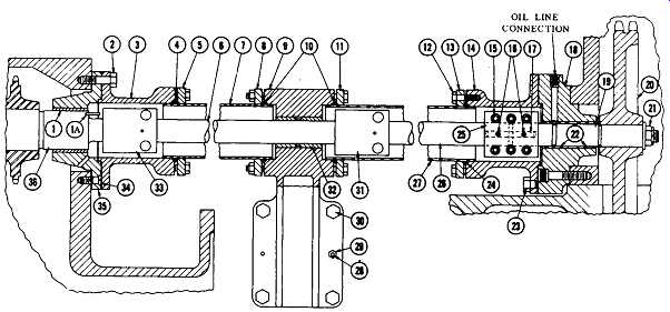
FIG. 12 Power train layshaft for a two-stroke gas engine. (Cooper-Bessemer
Reciprocating, Grove City, PA)
The Turbocharger
A turbocharger consists of a centrifugal blower and turbine mounted on a common shaft surrounded by five major castings. It’s mounted on a diesel or gas engine and is driven by the engine exhaust gases. The exhaust gases, due to their elevated temperatures and high velocity, transmit enough energy to the turbine and blower to force 50 to 100 percent more air into the engine for scavenging and combustion. This additional air "supercharges" the engine, making it possible to burn more fuel to produce additional power. The scavenging air flow provides cooling for the cylinder head, cylinder walls, and piston. For this reason, a greater amount of fuel can be burned without harmful effects to the engine and turbocharger due to excessive heat.
The turbocharger output is proportional to engine load. It automatically slows down if the engine load is decreased and speeds up and delivers more air if engine load is increased or if barometric pressure drops. It maintains engine operation at or near optimum air-fuel ratio, resulting in high engine efficiency over a very wide operating range. The turbocharger operates in one direction only, regardless of engine rotation. Turbochargers used on "pure turbocharged" engines are equipped with air-assist nozzles on the blower diffuser. Air discharged through these nozzles, at the time of engine starting, assists in purging the engine and delivers sufficient energy to the turbocharger to maintain the required air-fuel ratio until exhaust energy becomes sufficient to drive the turbocharger.
Engine Control System
The control system of the engine has two purposes: first, to ensure safety, and second, to provide optimum operation. The pneumatically operated safety shutdown controls will stop the engine and indicate (on the control panel) the system in which the unsafe condition occurred. Any one of the safety shutdown devices (some are optional) will vent control air pressure from the fuel gas shutoff and vent valve to stop the engine should any of the following unusual malfunctions occur:
1. High jacket water temperature.
2. High air manifold temperature.
3. Force-feed lubricator, power cylinder, or compressor cylinder failure.
4. Low lubricating oil pressure.
5. High lubricating oil temperature.
6. Engine over-speeding.
7. High main bearing temperature.
8. High connecting rod bearing temperature.
9. Excessive turbocharger vibration.
10. Excessive engine vibration.
1. Low crankcase oil level.
2. Low aftercooler water pressure.
3. Low jacket water pressure.
Any number of these sensing devices as required by the installation can be used in the system to stop the engine via fuel gas shutoff and vent valves.
Engine speed is controlled by the main governor. The governor most commonly used is a Woodward hydraulic relay type. However, other types may be used according to service requirements and user preference. The governor is mounted on the auxiliary drive housing and driven through a set of bevel gears. The bevel gears are lubricated from the engine lube oil system. The governor is a self-contained unit with its own lubricating system. Governor signals are transmitted to the fuel gas accelerating valve to control the flow of gas to the headers in accordance with engine requirements. An increase in load causes a decrease in engine RPM, which in turn causes the governor to further open the fuel gas-regulating valve to admit more fuel gas to the engine. A decrease in load has the opposite effect. The result is that constant speed is maintained regardless of load and speed conditions.
Fuel gas header pressure and inlet manifold pressure change with load and speed. The manifold pressure regulator balances fuel gas pressure against air manifold pressure. Any change in sensed pressures will correspondingly move a pilot valve that directs oil under pressure to an actuator. This actuator repositions the exhaust bypass butterfly valve, thus maintaining the correct air manifold pressure in accordance with engine requirements.