AMAZON multi-meters discounts AMAZON oscilloscope discounts
PART A: Gas Turbine Cycles
From a thermodynamic point of view, a gas turbine- or gas turbine engine - is a machine that accepts and rejects heat at different energy levels and, in the process, produces work. While this work is converted to pressure and velocity energy in the aircraft jet engine, the commercial or industrial gas turbine is arranged to convert this work into shaft rotation or, more correctly, torque.
The gas turbine ( Fig. A-1) consists of an air compressor and gas combustion, gas expansion, and exhaust sections. The gas turbines cycle is composed of four energy exchange processes: an adiabatic compressor, a constant-pressure heat addition, an adiabatic expansion, and a constant-pressure heat rejection. The four thermodynamic processes can be accomplished either in an open-cycle or a closed- cycle system. The open-cycle gas turbine takes ambient air into the compressor as the working substance that, after compression, is passed through a combustion chamber where the temperature is raised to a suitable level by the combustion of fuel. It’s then expanded inside the turbine and exhausted back to the atmosphere.
Most industrial-type gas turbines work on this principle, and Fig. A-2 and A-3 illustrate simple, open-cycle gas turbines. The use of two or more hot gas expansion stages makes it possible to produce the two-shaft turbine of Fig. A-3. This configuration has greater speed flexibility than single-shaft machines.
The closed-cycle gas turbine uses any gas as the working substance. The gas passes through the compressor, then through a heat exchanger where energy is added from a source, then expanded through the turbine and finally back to the compressor through a pre-cooler where some energy may be rejected from the cycle.
Perhaps the most important reasons why process plants use gas turbines are summarized as high system reliability and high combined energy system and process efficiency. Where the forced outages of a single driver can shut down an entire complex, highest reliability is a must. For projects involving process system modifications of a new process design, choosing the most reliable turbine or energy system rather than maintaining an already existing process design can result in significantly higher reliability and reduced financial loss due to excessive process shutdowns.
With regard to the second point, high efficiency, the potential user may be confronted with an apparent mismatch between project needs and available machine sizes. In that case, it may save considerable money initially and over the life of the plant to revise the process design to match the best equipment and energy system available.
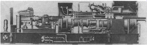
Above: Fig. A-1 Typical industrial gas turbine. (General Electric Company,
Schenectady, NY.)

Above: Fig. A-2 Single-shaft, simple open-cycle industrial gas turbine. (General
Electric Company, Schenectady, NY.)
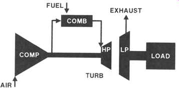
Above: Fig. A-3 Two-shaft, simple open-cycle industrial gas turbine. (General
Electric Company, Schenectady, NY.)
Simple-Cycle Gas Turbines
Most gas turbines in the process industries are operating in base load, or continuous, service. Fuel costs are an important consideration in determining the type of prime mover in these applications. However, there are hundreds of simple-cycle gas turbines installed in many areas of the world where fuel is relatively low cost, in underdeveloped areas, or in remote or harsh environments. Examples of simple- cycle gas turbine installations are in Indonesia, the North Sea, the Sahara Desert, and the Alaskan North Slope. The advantages of simple-cycle gas turbines include:
- -- Low capital cost
- -- Minimum installation cost
- -- No external power or cooling water required
- -- Minimum operating labor
- -- Low maintenance costs
- -- High reliability
- -- High availability
The disadvantage of the simple-cycle gas turbine is its relatively low system efficiency and higher fuel costs, compared with gas turbine systems with exhaust heat recovery.
===
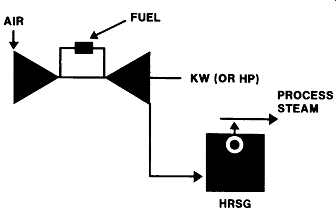
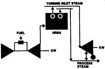
Above: Fig. A-4 Typical industrial gas turbine cycle employing heat recovery
steam generator (HRSG). (General Electric Company, Schenectady, NY.) TYPICAL
INDUSTRIAL GAS TURBINE CYCLES AIR FUEL KW (OR HP) PROCESS STEAM HRSG
===
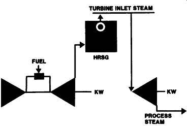
Above: Fig. A-5 Combined cycles employ both gas and steam turbines. (General
Electric Company, Schenectady, NY.) TYPICAL INDUSTRIAL GAS TURBINE CYCLES TURBINE
INLET STEAM; FUEL O HRSG KW PROCESS STEAM
==
Above: Fig. A-6 Cycle flexibility is provided through utilization of a two-level
heat recovery steam generator and admission-extraction steam turbine. (General
Electric Company, Schenectady, NY.) TYPICAL INDUSTRIAL GAS TURBINE CYCLES --
STEAM
===
Heat Recovery Cycles
Usually the economics of gas turbines in the process industries depend on effective use of the gas turbine exhaust energy. The most common use of this energy is for steam generation in heat recovery steam generators (HRSG), unfired, as well as fired designs. However, the gas turbine exhaust gases can also be used as a source of energy for unfired and fired process fluid heaters and direct drying applications, as well as for combustion air for power boilers, reformers, or other process equipment.
One of the more common gas turbine/heat recovery cycles is one where the exhaust energy is used to generate steam at conditions suitable for the process steam header ( Fig. A-4). The HRSG may be unfired or have supplementary firing to increase steam output. Power generation capability for these gas turbine-HRSG cycles, per unit of heat delivered to process, ranges from approximately 150 to 250 kW per million British thermal units (Btu)-net heat to process (NHP). Generation of steam at higher initial steam conditions than those required for process heat will allow use of a steam turbine in the cycle in addition to the gas turbine, as shown in Fig. A-5. This combined cycle will result in a higher power generation-to-process heat ratio than the gas turbine-HRSG cycle shown in Fig. A-4, with power generation in the range of 200 to 400 kW per million Btu NHP.
A typical upper limit for steam conditions of unfired HRSGs is 1315 pounds per square inch gauge (psig)/950~ The HRSG steam temperature is usually 75 to 100 ~ or more below the gas turbine exhaust gas temperature. Fired HRSGs have been applied with steam generation pressure and temperature as high as 1525 psig/955 ~ A multiple-pressure-level HRSG combined-cycle system is shown in Fig. A-6. This arrangement is common for unfired and moderately fired (up to approximately 1200 ~ HRSGs. The multipressure-level HRSG results in increased recovery of the gas turbine exhaust energy compared with an unfired, single- pressure-level HRSG system, thus increasing the cycle thermal efficiency.
The steam turbine in a combined cycle may be a noncondensing or a condensing design, depending primarily on process heat requirements. The steam turbine design shown schematically in Fig. A-6 provides considerable cycle flexibility in industrial process application. The condenser provides a heat sink for HRSG steam-generating capability in excess of that extracted from the turbine for process use. Furthermore, the optional admission capability permits the introduction of lower pressure process steam into the turbine for expansion to the condenser during times of excess low-pressure steam.
Even though gas turbines are not available in an infinite number of ratings, the application of a helper steam turbine may permit utilization of the capability of standard, proven gas turbine units in certain mechanical drive or generator drive applications. In this cycle, shown schematically in Fig. A-7, the helper steam turbine can argument gas turbine power generation as load requirements vary. In most instances, depending on horsepower and steam conditions, the helper steam turbine can be mounted on the gas turbine base and shipped as an integral driver unit to minimize installation costs. For instance, base-mounted, noncondensing helper steam turbines for a medium-to-large gas turbine may range from small, single-stage turbines to multistage, multivalve turbines rated up to 8000 horsepower (HP). Control of the steam turbine helper and the gas turbine is integrated into a single governing system.
In the regenerative-cycle gas turbine, exhaust heat is recovered by heating the turbine's combustion air after compression, but before it enters the combustion chambers to reduce gas turbine fuel. The Fig. A-8 schematic diagram shows a regenerative-cycle gas turbine followed by a low-pressure process HRSG. One of the consequences of the low fuel consumption of the regenerative-cycle gas turbine is a reduction of the gas turbine exhaust gas temperature to approximately 600 ~ This cycle arrangement can be an option when a relatively small amount of process steam is required.
===
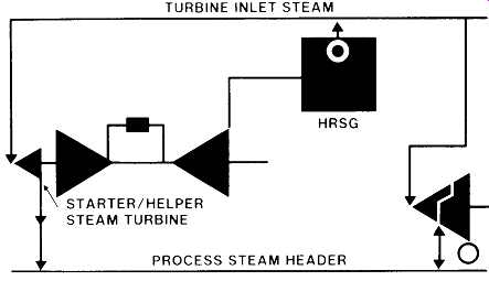
Above: Fig. A-7 Starter-helper steam turbine arrangement in a combined gas
turbine cycle. TURBINE INLET STEAM I STEAM TURBINE PROCESS STEAM HEADER; (General
Electric Company, Schenectady, NY.)
===
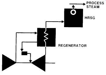
Above: Fig. A-8 Regenerative-cycle gas turbine followed by a low-pressure
process HRSG. (General Electric Company, Schenectady, NY.) 850 TO 1250 PSIG;
PROCESS STEAM HRSG REGENERATOR 600 PSIG TO PROCESS; PROCESS HEAT J RECOVERY
BOILERS

Above: Fig. A-9 Typical refinery power plant schematic shows power generator
drives predominating. (General Electric Company, Schenectady, NY.)
===
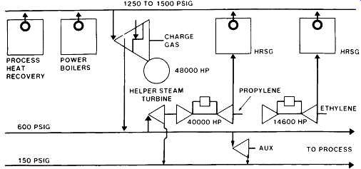
Above: Fig. A-10 Ethylene plant with combined cycle drives. (General Electric
Company, Schenectady, NY.) PROCESS STEAM; PROCESS POWER HEAT BOILERS RECOVERY
600 PSIG 150 PSIG 1250 TO 1500 PSIG J ~ AUX TO PROCES~ G z
~EXHAUST SUPPLEMENTARY
-- _ ~ FIRING RETURN OIL COOLER , GAS TURBINE KW OIL HEATED FI
====
In petroleum refineries, power generator drives predominate, as illustrated in Fig. A-9. Petroleum production facilities, both onshore and offshore, make use of gas turbines for gas reinjection compressor, water-flood pumping, and power generator drive applications.
In modem ethylene production facilities, three and sometimes four major compressor strings require variable speed drivers. The charge gas compressor driver is typically an extraction-condensing steam turbine that supplies 600 psig steam to the cracking process. Additional process steam can be furnished by the extraction- condensing propylene compressor driver or sometimes by a noncondensing ethylene driver. However, typical energy balances require large quantities of power boiler fuel and large blocks of condensing power. To reduce overall fuel consumption and cooling water requirements, gas turbines have been selected as the propylene and ethylene compressor drivers for a number of large plants. A typical layout is shown in Fig. A-10.
TABLE A.1 Data Performance Specifications for Major Mechanical Drive Gas Turbines
TABLE A.2 Performance Specifications for Major Electric Power Generator Drive Gas Turbines
One major plastics plant uses the gas turbine exhaust to first heat the oil used in a high-temperature distillation process. The exhaust gases then pass to a supplementary fired heat recovery steam generator where plant process steam is produced.
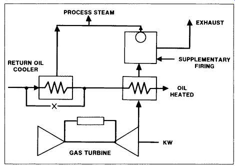
Fig. A-11 depicts this sequence.
Heavy-duty industrial gas turbines are available as both simple cycle and regenerative cycle machines. These can be single- or two-shaft configurations for both
mechanical and generator drive applications. Mechanical drive gas turbines cover a range from 14,000 HP to 45,000 HP at International Standards Organization (ISO) conditions burning gaseous fuels. One leading U.S. manufacturer has five different models that can be used as mechanical- or power generation-type turbines.
TABLE A.1 and 3A.2 indicate cycle, fuel used, output, heat rate, and shaft speed of both mechanical drive and generator drive gas turbines available from this manufacturer. Of course, other manufacturers may produce machines in different or overlapping size categories.
PART B: Life Cycle Usage
Estimated Hot-Gas Path Parts Lives (Peaking Duty)
The application, cyclic or continuous duty, starting frequency and time, internal temperatures as a result of loading duty, and type of fuel used all determine parts life and maintenance cost. A peaking plant has many thermal cycles, resulting in a requirement to inspect the unit on a shorter fired-hour basis than is required with a continuous-duty unit. The normal variance of peaking units will be one start per one fired hour to one start per six fired hours. Within this range, the planned hot-gas path inspection should take place each 6,000 to 10,000 fired hours of operation, depending on the evaluations made at combustion inspections, factoring in the effects of fuel and metal temperature. This is approximately one third of the fired hours expected to be attained on a continuous-duty unit before an inspection will be routinely scheduled. At this inspection, the affected parts may be replaced for minimum downtime or may be repaired and reinstalled in the unit with a longer outage. The parts under consideration for this inspection interval are transition pieces, first-stage nozzles, and second-stage nozzles. The combustion system parts will be repaired, using these criteria at approximately 1000- to 1500-hour intervals, or once per year.
These parts include the combustion caps, liners, and cross-fire tubes.
Turbine buckets should require little repair except for foreign object damage caused by ingesting external material or for restoration of bucket tip clearances for continued efficiency.
The inspection interval hours stated previously for the hot-gas path parts will be maximized by optimization of the combustion system. It’s important that the maintenance program be used to maintain proper control settings and that the combustion parts be kept in proper working order. The fuel nozzles, for example, will have a direct effect on the liners, transition pieces, and nozzles. Balanced firing temperatures will maintain minimum temperature differentials and assure that one combustion chamber and nozzle segment won’t experience excessive temperatures. This occurs because the transition pieces and first-stage nozzles are exposed to the direct discharge from the combustion process.
First- and second-stage turbine nozzles can be repaired several times with a resultant extension of the total life. The economic determination of repair versus replacement will govern the feasibility and number of times the nozzles are repaired.
Operating Factors Affecting Component Lives
The factors having the greatest influence on the life of parts for any given machine are type of fuel, starting frequency, load duty, environment, and maintenance practices.
Fuel
The effect of the type of fuel on parts life is associated with the radiant energy in the combustion process and the ability to atomize various liquid fuels. Therefore, natural gas, which does not require atomization, has the lowest level of radiant energy and will produce the longest life of parts. Diesel fuels will produce the next highest life, and the crude oils and residual oils, with higher radiant energy and more difficult atomization, will produce shorter life of parts, as shown in Fig. B-1.
Contaminants in the fuel also affect the maintenance interval. This is particularly true for liquid fuels where dirt results in accelerated replacement of pumps, metering elements, and fuel nozzles. Contaminants in fuel gas systems can erode or corrode control valves and fuel nozzles. Filters must be observed and changed when practical to assure against the carrying of these contaminants through the fuel system. Clean fuels will invariably result in reduced maintenance and extended parts life.
===
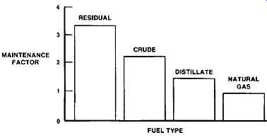
Above: Fig. B-1 Effect of fuel on gas turbine maintenance. (General Electric
Company, Schenectady, NY. ) MAINTENANCE FACTOR; RESIDUAL , , CRUDE DISTILLATE , , FUEL TYPE NATURAL GAS
===
Above: Fig. B-2 Effect of number of starts on gas turbine maintenance. (General
Electric Company, Schenectady, NY.)
Above: Fig. B-3 Effect of load duty on gas turbine maintenance. (General
Electric Company, Schenectady, NY.)
Starting Frequency and Time
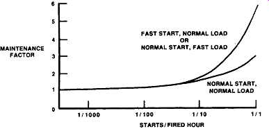
Each start, stop, and load change of a combustion gas turbine subjects its hot-gas path parts to thermal cycling. Control systems are designed, programmed, and adjusted to apply temperatures that are compatible with material properties to minimize required maintenance from this cycling effect. However, a unit in a peaking application will demonstrate parts lives ( Fig. -19 and 3-20) that are shorter than a similar unit in base-load continuous duty service, as with any equipment subject to cycling conditions.
The normal programmed starting time for a peaking unit is designed to minimize transient thermal stresses and maximize parts life. Fast start/load programs are available that compromise these objectives and are therefore used primarily in emergencies or to periodically demonstrate fast starting capability. These effects are shown in Fig. B-2 as a function of starting frequency. The maintenance penalty for fast start/load occurs mainly from the load application, since a fast start from standstill to rated speed occurs in approximately 2.25 minutes, with a temperature change of 800 ~ maximum; but a fast load application is accomplished in 30 seconds, with a resulting temperature change of 1000 ~ The differences in rate of temperature change are obvious and explain the increased maintenance cost.
Load Duty
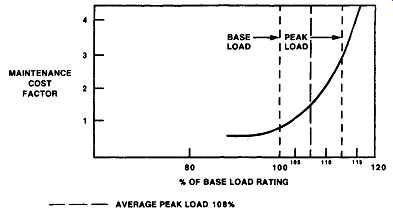
Utility units are usually supplied with a designated peak and peak reserve rating higher than the normal base rating. These ratings will affect the life of hot-gas path parts due to the higher firing temperatures that exist in the unit ( Fig. B-3). These ratings are used to allow the operator flexibility in the use of this equipment for the system needs. Usual daily peaking applications justify loading the units only to the base rating, with peak and peak reserve capabilities assigned for additional flexibility in emergency conditions.
Maintenance requirements are affected by the assignment of loading temperatures, and the economics of use must be balanced to arrive at overall use factors.
PART 3: Specific Maintenance Inspections
The combustion gas turbine, as does any rotating power equipment, requires a program of planned periodic inspection, with repair and replacement of parts to achieve optimum availability and reliability. The major structural components of the heavy-duty combustion gas turbine are designed according to long-established standards derived from steam turbine design and manufacture. Major differences occur between the steam turbine and the combustion gas turbine due to the fact that the combustion gas turbine is a complete, self-contained, prime mover. This combustion process to develop energy does not require a boiler with its associated limitations; therefore, the cycle temperatures are considerably higher. The parts that are unique to the gas turbine because of this feature are combustion caps, liners, and transition pieces. These, along with the turbine nozzles and buckets, are referred to as the "hot-gas path" parts.
The inspection and repair requirements of the gas turbine lend themselves to establishing a pattern of inspections, starting with very minor work and increasing in magnitude to a major overhaul, and then repeating the cycle. These inspections can be optimized to reduce unit outages and maintenance cost for the user's specific mode of operation, while maintaining maximum availability and reliability. Inspections can be classified as operational or shut down. The operational inspections are used as indicators of the general condition of the equipment and as guides for planning the disassembly maintenance program. The entire scope of inspections can be described as standby, running, combustion, hot-gas path, and major.
Standby Inspection
Standby inspections pertain particularly to gas turbines used in intermittent service, such as peaking and emergency duty. Starting reliability is of prime concern, as a delay in starting usually means that the demand for the unit has passed. This includes routine servicing of the battery system, lubrication, changing of filters, checking oil and water levels, cleaning relays, checking device calibrations, and other general preventive maintenance. This servicing can be performed in off-peak hours without interrupting the availability of the turbine. A periodic test run is an essential part of the standby inspection.
TABLE C.1 Typical Running Inspections Recommended for Gas Turbines; Load versus exhaust temperature; Vibration; Fuel flow and pressure; Exhaust temperature control; Exhaust temperature variation; Start-up time
Running Inspection
Running inspections consist of the observations made while a unit is in service. The turbine should be observed on a programmed schedule, which should be established as part of the unit maintenance program consistent with the operator's requirements.
Operating data should be recorded to permit an evaluation of equipment performance and maintenance requirements. Typical running inspections ( TABLE C.1) include load versus exhaust temperature; vibration; fuel flow and pressure; exhaust temperature control and variation; and startup time.
The general relationship between load and exhaust temperature should be observed and compared with previous data. Ambient temperature and barometric pressure will have some effect on the absolute temperature level. High exhaust temperature can be an indicator of deterioration of internal parts, excessive leaks, axial-flow compressor fouling, or improper control settings. Initial startup data should be used as the reference point for checking.
Power loss resulting from deteriorated parts or leaks may require disassembly of the turbine to restore power. This can be done with on-site labor and equipment.
Loss due to dirt fouling of the axial flow compressor can usually be restored by cleaning the compressor while in service. This is accomplished by injecting 10 to 20 pounds of mild abrasives such as hard rice or screened crushed nut shells into the compressor inlet. A successful cleaning will reduce the exhaust temperature for a given load and will increase the compressor discharge pressure. If the need to clean the compressor is frequent, the causes of the fouling condition should be determined and corrected.
The vibration level of the unit should be observed and recorded. Minor changes will occur with changes in operating conditions. However, major changes, or a continuous trend to increase, indicate that corrective action is required.
The fuel system should be observed for general fuel flow versus load relationship. Fuel pressures through the system should be observed. Changes in fuel pressure can indicate that fuel nozzle passages are plugged or fuel metering elements are damaged or out of calibration.
Probably the most important control function to be observed is the exhaust temperature-fuel override system and its backup overtemperature trip system.
Routine verification of the operation and calibration of these devices will minimize wear on the hot-gas path parts.
The variation in turbine exhaust temperature should be measured. An increase in temperature spread indicates combustion deterioration or fuel distribution problems. If not corrected, reduced life of downstream parts can be expected.
Startup time (when the gas turbine is new) is an excellent reference against which subsequent operating parameters can be compared and evaluated. A curve of starting parameters of speed, fuel signal, exhaust temperature, and critical sequence benchmarks versus time from the initial start signal will give a good indication of the condition of the control system. Deviations from normal conditions help pinpoint impending trouble, changes in calibration, or damaged components.
Combustion Inspection
This is a shutdown inspection to inspect combustion liners and fuel nozzles; these are recognized as the first parts requiring replacement and repair for a good maintenance program. Proper attention to these items will optimize the life cycle of downstream parts, such as turbine nozzles and buckets.
Fig. C-1 illustrates the section of a typical unit that is disassembled for this inspection. The combustion liners and fuel nozzles should be removed and replaced with new or repaired liners and new or clean fuel nozzles. This method of inspecting allows for minimum unit downtime and maximum utilization of manpower. A visual inspection of the transition pieces and nozzles (first-stage) at this time optimizes the scheduling of the hot-gas path inspection. This visual inspection is accomplished by an optical instrument called a "borescope," which is inserted through the combustion liner area to allow examination of the transition pieces and first-stage nozzle.
The typical intervals for combustion inspections are shown in TABLE C.2 and 3C.3.
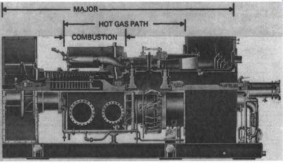
Above: Fig. C-1 Major areas of gas turbine inspection. (General Electric
Company, Schenectady, NY.)
TABLE C.2 Typical Inspection Intervals for Gas Turbines in Continuous Duty
Combustion Hot Gas Major
A. Gas - - 30,000-40,000 Distillate 10,000-14,000 - 20,000- 28,000 B. Gas 8,000-10,000 16,000- 20,000 30,000-40,000 Distillate 5,000- 7,000 10,000-14,000 20,000- 28,000
*One start per 1,000 fired hours.
A. Continuous process- Gas turbine outage results in process shutdowns. Loss in production exceeds savings from optimum maintenance.
B. interruptible process- Scheduled outages coincide with other equipment inspections (i.e., under- writer requirement). Maintenance costs optimized.
TABLE C.3 Typical Inspection Intervals Recommended for Gas Turbines in Peaking Service
TABLE C.4 Recommended Inspection Intervals Linked to Fired Hours, Starts, and Elapsed Time
Whichever Comes First Fired Hours Starts Time Combustion inspection Natural gas 8,000-10,000 300-400 Annually Distillate 5,000- 8,000 300 -400 Hot-gas path Natural gas 20,000-24,000 600-800 - Distillate 20,000- 24,000 600- 800 - Major inspection Natural gas 42,000-48,000 1,600-2,400 6 Years Distillate 42,000-48,000
TABLE C.5 Recommended Work Scope for Major Inspections*
Part Action Inspection For Bearings, seals Clean Blading Clean manually, loose parts check Buckets Remove from rotor-grit blast- loose parts check Turbine wheel Clean, loose parts check in dovetail area Journals and seal fits Inlet system and exhaust system Inspect, repair, paint
*Step 1: Same as for combustion and hot-gas-path inspections; Step 2: Remove remaining upper half casings and beating covers; Step 3: Remove rotors.
Wear, fouling, leaks, wiping, scoring, deterioration of babbitt Foreign object damage, erosion, corrosion, cracks, fouling Foreign object damage, cracks, erosion, corrosion Cracks in dovetail area Wear, scoring, wear on seal fits
Corrosion, cracks, loose parts
Hot-Gas Path Inspection
This inspection includes the work necessary for a combustion inspection plus the removal of the upper half turbine shell, and on applicable turbines, removal of the upper half combustion chamber wrapper.
TABLE C.6 Estimated Time to Perform Recommended Gas Turbine Inspections on Popular GE Sizes Inspection Model Hours Work Shifts
Combustion 5001 160 5
6001 240 6 9001 480 10 Hot-gas path 5001 480 10 6001 672 12 9001 1,120 20 Major 5001 1,280 20 6001 1,600 25 9001 2,560 40
The inspection involves all hot-gas path parts. These include the turbine buckets, shrouds, nozzles, transition pieces, and exhaust hood turning vanes. The typical recommended intervals are given in TABLE C.4.
Major Inspection
A major inspection includes the work items outlined for combustion inspections and hot-gas path inspections; it also includes "laying the turbine on the half shell," and completely inspecting the axial flow compressor stator and rotor parts, turbine buckets and shrouds, bearings, and seals. TABLE C.5 gives the recommended work scope for major inspections and TABLE C.6 gives estimated man-hours and work shifts for popular gas turbines.