AMAZON multi-meters discounts AMAZON oscilloscope discounts
. In process plants, gas turbines are used in mechanical drive or power generation applications. They are more efficient than steam turbines and their simple cycle thermal efficiency can be greatly increased by waste heat recovery (combined cycle) and other cycle adaptions discussed later in this section.
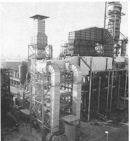
In the gas turbine field, information flow starts with the highest budgets and most demanding technological requirements in research and development and moves towards industry. Which means that technology flow goes from NASA to aircraft engines to land-based gas turbines. The 1950s provided industry with a large shot in the gas turbine's technological arm in terms of efficiency, good design, operational features, environmental correctness and every other commercial facet. Nowadays, a number of industrial engines made by manufacturers who also make aircraft engines, such as Rolls-Royce and General Electric, are essentially similar to their aircraft engine sibling but are mounted on a skid. Support systems however, both operational and condition monitoring, won’t have the same complexity and degrees of redundancy as the aircraft engine counterpart.
The factors which can influence selection of the gas turbine versus the steam turbine in power generation are as varied as the potential users for them. High efficiency is often quoted as the reason for selection of the gas turbine versus the steam turbine. While this is true, in most of the high-growth areas of the world, the choice is made mainly on the basis of readily available, inexpensive fuel. Good illustrations of this fact are China with its high-sulphur coal and Thailand with its lignite. Both fuels occur naturally, are used in steam turbine plants and have been responsible for bad pollution scenarios that both countries are playing "catch up" with. Both these countries' interest in the gas turbine in power generation service is as a peaking unit, as gaseous fuel is an expensive commodity for countries where it doesn't occur naturally. In SE Asia, Japan is the only country that pays the premium for buy liquid natural gas (LNG). They do this in order to maintain the toughest environmental standards in the region, is Japan.
The gas turbine and systems associated with it are often more complex in terms of operational systems and repairability than the steam turbine. In many instances, the main reasons for selection of the gas turbine is its versatility with respect to size, at the small horsepower end. In oil and gas production for instance, varying mixed field volumes require that gas compression occur in smaller packages that can be started or shut down with little or no lead time, as opposed to one larger unit.
There is also the question of fuel availability. Gas pipeline transport compressors are driven by turbines that run on the fuel they contain. Pumps that transport water away from mixed field separation are generally driven by gas turbines, although in some instances electric motor drivers are used if power is cheap enough.
In these and many other applications, mature and reliable gas turbine models are available. Also in power generation, new technology has put some of the latest models of gas turbines in a size category that was otherwise the exclusive domain of steam turbines.
Consider also that coal gasification for running gas turbines has very recently reached commercial standards in some applications in the US and Europe. With major current improvements in gas turbine system optimization, metallurgical and design development and component repairability, there will be no stopping the gas turbine when this technology gains a foothold globally.
Once the choice is made for a gas turbine, factors that may influence the particular unit selected, include its track record on reliability and availability. Cost per fired hour, spare parts usage and parts repairability are governed by design features. In the case of remotely located or operated plants, such as high Arctic or unmanned stations, reliability and availability feature highly enough that users may favor oversized machinery (by as much as 100%) versus a newer model that fits the kilowatt requirement. Efficiency and fuel flexibility are also major factors.
Environmental factors, such as NOx emissions ratings for burner designs, lower temperature designs (that affect NOx production rates), water injection capabilities, ability to burn lower grade fuels (such as residual fuel), play an increasingly large part in selection. This is a large enough topic that it will be covered in depth in a separate guide: Environmental Engineering and Management: Sustainable Development in the Power Generation, Oil & Gas and Process Industries (Butterworth- Heinemann, 1998). This sectionhowever, does include a detailed look at one low NOx burner design in commercial operation.
Despite all these technical considerations, by far the biggest factor in gas turbine sales in fast developing countries is the financing or monetary incentives that the OEM (original equipment manufacturer) can provide. In one instance, a customer turned down a model he preferred technically, in favor of another where the OEM paid him the difference in fuel efficiency (a sizable 4%) over the estimated life of the engines - which essentially meant no capital outlay with initial purchase of the units.
DESIGN
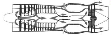
Basically, the gas turbine consists of a compressor that draws in atmospheric air and compresses it to a certain power ratio; a combustion section at the start of which fuel is let in and ignited; and a turbine section through which the combustion gases expand. In power generation applications, the power turbine drives a generator.
In mechanical drive applications, the power turbine powers the item being driven (generally a compressor or pump). Sometimes a gearbox is used to alter the speed of the power turbine. A discussion of gas turbine cycles forms one of the appendices of this section.
The major components and processes of the gas turbine, as well as guidelines in selecting one, will now be discussed.
The Compressor
In the gas turbine engine, compression of the air before expansion through the turbine is effected by one of two basic types of compressor, one giving centrifugal flow and the other axial flow. Both types are driven by the engine turbine and are usually coupled direct to the turbine shaft.
The centrifugal flow compressor ( Fig. -1) is a single-or two-stage unit employing an impeller to accelerate the air and a diffuser to produce the required pressure rise. The axial flow compressor is a multistage unit employing alternate rows of rotating (rotor) blades and stationary (stator) vanes, to accelerate and diffuse the air until the required pressure rise is obtained. In some cases, particularly on small engines, an axial compressor is used to boost the inlet pressure to the centrifugal.
With regard to the advantages and disadvantages of the two types, the centrifugal compressor is usually more robust than the axial compressor and is also easier to develop and manufacture. The axial compressor, however, ingests far more air than a centrifugal compressor of the same frontal area and can be designed to attain much higher pressure ratios. Since the airflow is an important factor in determining the amount of thrust, this means the axial compressor engine will also give more thrust for the same frontal area. This, plus the ability to increase the pressure ratio by addition of extra stages, has led to the adoption of axial compressors in most engine designs. However, the centrifugal compressor is still favored for smaller engines where its simplicity and ruggedness outweigh any other disadvantages.
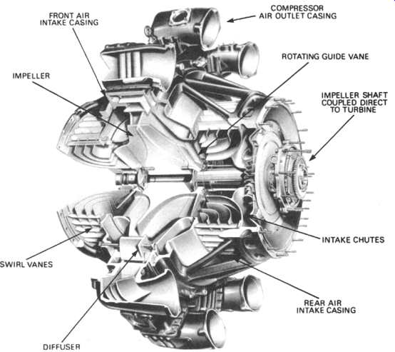
Above: Fig. -1 A typical centrifugal flow compressor. (Courtesy: Rolls-Royce)
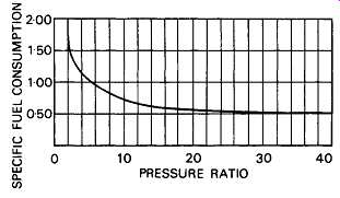
Above: Fig. -2 Specific fuel consumption and pressure ratio. (Courtesy: Rolls-Royce)
The trend to high pressure ratios which has favored the adoption of axial compressors is because of the improved efficiency that results, which in turn leads to improved specific fuel consumption for a given thrust ( Fig. -2).
Combustion Chambers
The combustion chamber ( Fig. -3) has the difficult task of burning large quantities of fuel, supplied through the fuel spray nozzles, with extensive volumes of air, supplied by the compressor and releasing the heat in such a manner that the air is expanded and accelerated to give a smooth stream of uniformly heated gas at all conditions required by the turbine. This task must be accomplished with the minimum loss in pressure and with the maximum heat release for the limited space available.
The amount of fuel added to the air will depend upon the temperature rise required. However, the maximum temperature is limited to within the range of 850 to 1700 ~ by the materials from which the turbine blades and nozzles are made.
The air has already been heated to between 200 and 550~ by the work done during compression, giving a temperature rise requirement of 650 to 1150 ~ from the combustion process. Since the gas temperature required at the turbine varies with engine thrust, and in the case of the turbo-propeller engine, upon the power required, the combustion chamber must also be capable of maintaining stable and efficient combustion over a wide range of engine operating conditions.
Efficient combustion has become increasingly important because of the consequent increase in atmospheric pollution.
The Combustion Process
Air from the engine compressor enters the combustion chamber at a velocity up to 500 feet per second, but because at this velocity the air speed is far too high for combustion, the first thing that the chamber must do is to diffuse it, i.e. decelerate it and raise its static pressure. Since the speed of burning kerosene at normal mixture ratios is only a few feet per second, any fuel lit even in the diffused air stream, which now has a velocity of about 80 feet per second, would be blown away. A region of low axial velocity has therefore to be created in the chamber, so that the flame will remain alight throughout the range of engine operating conditions.
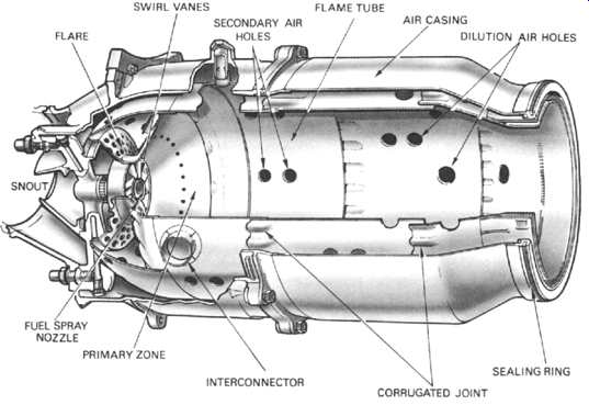
Above: Fig. -3 A combustion chamber. (Courtesy: Rolls-Royce)
In normal operation, the overall air/fuel ratio of a combustion chamber can vary between 45:1 and 130:1. However, kerosene will only burn efficiently at, or close to, a ratio of 15:1, so the fuel must be burned with only part of the air entering the chamber, in what is called a primary combustion zone. This is achieved by means of a flame tube (combustion liner) that has various devices for metering the airflow distribution along the chamber.
Approximately 20 percent of the air mass flow is taken in by the snout or entry section ( Fig. -4). Immediately downstream of the snout are swirl vanes and a perforated flare, through which air passes into the primary combustion zone. The swirling air induces a flow upstream of the center of the flame tube and promotes the desired recirculation. The air not picked up by the snout flows into the annular space between the flame tube and the air casing.
Through the wall of the flame tube body, adjacent to the combustion zone, are a selected number of secondary holes through which a further 20 percent of the main flow of air passes into the primary zone. The air from the swirl vanes and that from the secondary air holes interacts and creates a region of low velocity recirculation. This takes the form of a toroidal vortex, similar to a smoke ring, which has the effect of stabilizing and anchoring the flame ( Fig. -5). The recirculating gases hasten the burning of freshly injected fuel droplets by rapidly bringing them to ignition temperature.
It’s arranged that the conical fuel spray from the nozzle intersects the recirculation vortex at its center. This action, together with the general turbulence in the primary zone, greatly assists in breaking up the fuel and mixing it with the incoming air.
The temperature of the gases released by combustion is about 1,800 to 2,000 ~ which is far too hot for entry to the nozzle guide vanes of the turbine. The air not used for combustion, which amounts to about 60 percent of the total airflow, is therefore introduced progressively into the flame tube. Approximately a third of this is used to lower the gas temperature in the dilution zone before it enters the turbine and the remainder is used for cooling the walls of the flame tube. This is achieved by a film of cooling air flowing along the inside surface of the flame tube wall, insulating it from the hot combustion gases ( Fig. -6). A recent development allows cooling air to enter a network of passages within the flame tube wall before exiting to form an insulating film of air, this can reduce the required wall cooling airflow by up to 50 percent. Combustion should be completed before the dilution air enters the flame tube, otherwise the incoming air will cool the flame and incomplete combustion will result.
An electric spark from an igniter plug initiates combustion and the flame is then self-sustained.
The design of a combustion chamber and the method of adding the fuel may vary considerably, but the airflow distribution used to effect and maintain combustion is always very similar to that described.
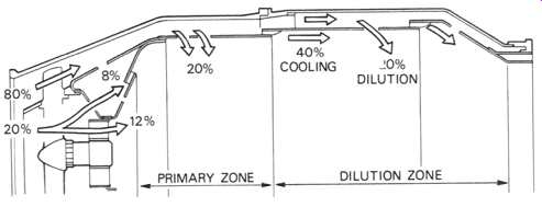
Above: Fig. -4 Apportioning the airflow. (Courtesy: Rolls-Royce)
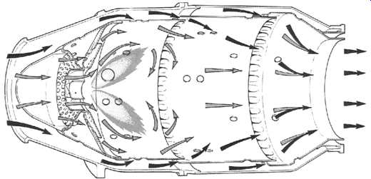
Above: Fig. -5 Flame stabilizing and general airflow pattern. (Courtesy: Rolls-Royce)
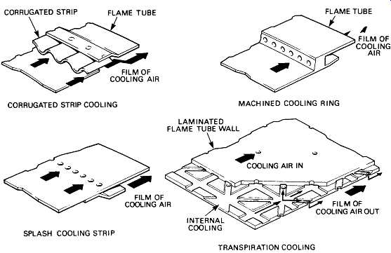
Above: Fig. -6 Flame tube cooling methods. FLAME TUBE CORRUGATED STRIP
FLAME TUBE; COOLI NG AIR CORRUGATED STRIP COOLING MACHINED COOLING RING LAMINATED
FLAME TUBE WALL OF COOLING AIR; COOLING AIR IN SPLASH COOLING STRIP INTERNAL
COOLING TRANSPIRATION COOLING FILM OF COOLING AIR OUT
Fuel Supply
Fuel supply can be gaseous, liquid or both (dual). Liquid fuel is supplied to the airstream by one of two distinct methods. The most common is the injection of a fine atomized spray into the recirculating airstream through spray nozzles. The second method is based on the pre-vaporization of the fuel before it enters the combustion zone.
In the vaporizing method the fuel is sprayed from feed tubes into vaporizing tubes which are positioned inside the flame tube. These tubes turn the fuel through 180 degrees and, as they are heated by combustion, the fuel vaporizes before passing into the flame tube. The primary airflow passes down the vaporizing tubes with the fuel and also through holes in the flame tube entry section which provide 'fans' of air to sweep the flame rearwards. Cooling and dilution air is metered into the flame tube in a manner similar to the atomizer flame tube.
Types of Combustion Chamber
There are two main types of combustion chamber in use for gas turbine engines.
These are the multiple chamber and the annular chamber.
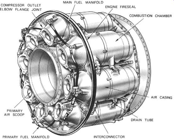
Above: Fig. -7 Multiple combustion chambers. (Courtesy: Rolls-Royce)
Multiple Combustion Chamber
This type of combustion chamber is used on centrifugal compressor engines and the earlier types of axial flow compressor engines.
The chambers are disposed around the engine Fig. -7 and compressor delivery air is directed by ducts to pass into the individual chambers. Each chamber has an inner flame tube around which there is an air casing. The air passes through the flame tube snout and also between the tube and the outer casing as already described.
The separate flame tubes are all interconnected. This allows each tube to operate at the same pressure and also allows combustion to propagate around the flame tubes during engine starting.
Annular Combustion Chamber
This type of combustion chamber consists of a single flame tube, completely annular in form, which is contained in an inner and outer casing ( Fig. -8). The airflow through the flame tube is similar to that already described, the chamber being open at the front to the compressor and at the rear to the turbine nozzles.
The main advantage of the annual chamber is that, for the same power output, the length of the chamber is only 75 percent of that of a tubo-annular system of the same diameter, resulting in considerable saving of weight and production cost.
Another advantage is the elimination of combustion propagation problems from chamber to chamber.
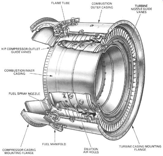
Above: Fig. -8 Annular combustion chamber. (Courtesy: Rolls-Royce)
The introduction of the air spray type fuel spray nozzle to this type of combustion chamber also greatly improves the preparation of fuel for combustion by aerating the over-rich pockets of fuel vapors close to the spray nozzle; this results in a large reduction in initial carbon formation.
A combustion chamber must be capable of allowing fuel to burn efficiently over a wide range of operating conditions without incurring a large pressure loss. In addition, if flame extinction occurs, then it must be possible to relight. In performing these functions, the flame tube and spray nozzle atomizer components must be mechanically reliable.
The gas turbine engine operates on a constant pressure cycle, therefore any loss of pressure during the process of combustion must be kept to a minimum. In providing adequate turbulence and mixing, a total pressure loss varying from about 3 to 8 percent of the air pressure at entry to the chamber is incurred.
The heat released by a combustion chamber or any other heat generating unit is dependent on the volume of the combustion area. Thus, to obtain the required high power output, a comparatively small and compact gas turbine combustion chamber must release heat at exceptionally high rates.
The Turbine
The turbine has the task of providing the power to drive the compressor and accessories and, in the case of engines which don’t make use solely of a jet for propulsion, of providing shaft power for a propeller or rotor. It does this by extracting energy from the hot gases released from the combustion system and expanding them to a lower pressure and temperature. High stresses are involved in this process, and for efficient operation, the turbine blade tips may rotate at speeds over 1500 feet per second. The continuous flow of gas to which the turbine is exposed may have an entry temperature between 850 and 1700 ~ and may reach a velocity of over 2500 feet per second in parts of the turbine.
To produce the driving torque, the turbine may consist of several stages each employing one row of stationary nozzle guide vanes and one row of moving blades ( Fig. -9). The number of stages depends upon the relationship between the power required from the gas flow, the rotational speed at which it must be produced and the diameter of turbine permitted.
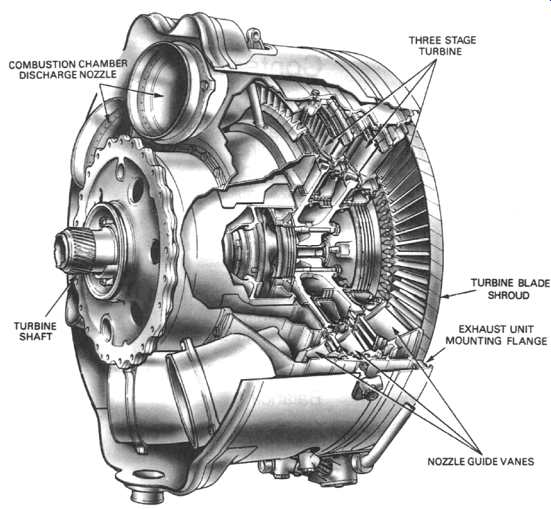
Above: Fig. -9 A triple-stage turbine with single shaft system. (Courtesy: Rolls-Royce)
The number of shafts, and therefore turbines, varies with the type of engine; high compression ratio engines usually have two shafts, driving high and low pressure compressors. On mechanical drive engines, driving torque is derived from a free power turbine ( Fig. -10). This method allows the turbine to run at its optimum speed because it’s mechanically independent of other turbine and compressor shafts.
In normal land-based applications, component weight is not a major consideration. For offshore platform applications, however, so as to arrive at a common model for all applications, most manufactures attempt to conserve weight. Also many of today's land-based gas turbines today are derived from aircraft engines, where weight is a major consideration.
The mean blade speed of a turbine has a considerable effect on the maximum efficiency possible for a given stage output. For a given output the gas velocities, deflections, and hence losses, are reduced in proportion to the square of higher mean blade speeds. Stress in the turbine disk increases as the square of the speed, therefore to maintain the same stress level at higher speed the sectional thickness, hence the weight, must be increased disproportionately. For this reason, the final design is a compromise between efficiency and weight. Engines operating at higher turbine inlet temperatures are thermally more efficient and have an improved power to weight ratio.
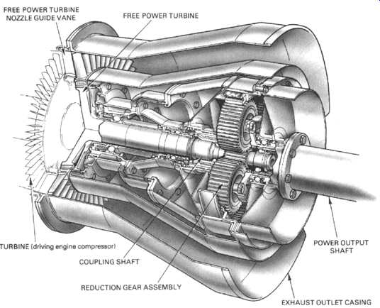
Above: Fig. -10 A typical free power turbine. (Courtesy: Rolls-Royce)
The design of the nozzle guide vane and turbine blade passages is based broadly on aerodynamic considerations, and to obtain optimum efficiency, compatible with compressor and combustion design, the nozzle guide vanes and turbine blades are of a basic aerofoil shape. There are three types of turbine; impulse, reaction and a combination of the two known as impulse-reaction. In the impulse type the total pressure drop across each stage occurs in the fixed nozzle guide vanes which, because of their convergent shape, increase the gas velocity whilst reducing the pressure. The gas is directed onto the turbine blades which experience an impulse force caused by the impact of the gas on the blades. In the reaction type the fixed nozzle guide vanes are designed to alter the gas flow direction without changing the pressure. The converging blade passages experience a reaction force resulting from the expansion and acceleration of the gas. Normally gas turbine engines don’t use pure impulse or pure reaction turbine blades but the impulse-reaction combination Fig. -11. The proportion of each principle incorporated in the design of a turbine is largely dependent on the type of engine in which the turbine is to operate, but in general it’s about 50 percent impulse and 50 percent reaction. Impulse-type turbines are used for cartridge and air starters.
From the previous description, it will be seen that the turbine depends for its operation on the transfer of energy between the combustion gases and the turbine.
This transfer is never 100 percent because of thermodynamic and mechanical losses.
When the gas is expanded by the combustion process, it forces its way into the discharge nozzles of the turbine where, because of their convergent shape, it’s accelerated to about the speed of sound which, at the gas temperature, is about 2500 feet per second. At the same time the gas flow is given a 'spin' or 'whirl' in the direction of rotation of the turbine blades by the nozzle guide vanes. On impact with the blades and during the subsequent reaction through the blades, energy is absorbed, causing the turbine to rotate at high speed and so provide the power for driving the turbine shaft and compressor.
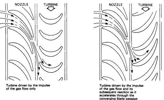
Above: Fig. -11 Comparison Between a pure impulse turbine and an impulse-reaction
turbine. Turbine driven by the impulse of the gas flow only. Turbine driven
by the impulse of the gas flow and its subsequent reaction as it accelerates
through the converging blade passage.
The torque or turning power applied to the turbine is governed by the rate of gas flow and the energy change of the gas between the inlet and the outlet of the turbine blades. The design of the turbine is such that the whirl will be removed from the gas stream so that the flow at exit from the turbine will be substantially "straightened out" to give an axial flow into the exhaust system. Excessive residual whirl reduces the efficiency of the exhaust system and also tends to produce jet pipe vibration which has a detrimental effect on the exhaust cone supports and struts.
It will be seen that the nozzle guide vanes and blades of the turbine are "twisted", the blades having a stagger angle that is greater at the tip than at the root, Fig. -12. The reason for the twist is to make the gas flow from the combustion system do equal work at all positions along the length of the blade and to ensure that the flow enters the exhaust system with a uniform axial velocity. This results in certain changes in velocity, pressure and temperature occurring through the turbine, as shown diagrammatically in Fig. -13.
The 'degree of reaction' varies from root to tip, being least at the root and highest at the tip, with the mean section having the chosen value of about 50 percent.
The losses which prevent the turbine from being 100 percent efficient are due to a number of reasons. A typical uncooled three-stage turbine would suffer a 3.5 percent loss because of aerodynamic losses in the turbine blades. A further 4.5 percent loss would be incurred by aerodynamic losses in the nozzle guide vanes, gas leakage over the turbine blade tips and exhaust system losses; these losses are of approximately equal proportions. The total losses result in an overall efficiency of approximately 92 percent.
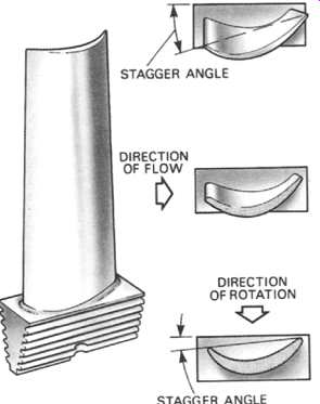
Above: Fig. -12 A typical turbine blade showing twisted contour. (Courtesy: Rolls-Royce)
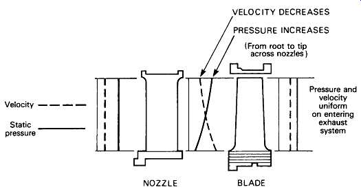
Above: Fig. -13 Gas flow pattern through nozzle and blade. (Courtesy: Rolls-Royce)
Velocity .... Static | pressure
VELOCITY DECREASES -- PRESSURE INCREASES
/// (From root to tip / across nozzles ) NOZZLE BLADE-- Pressure and velocity uniform on entering exhaust system
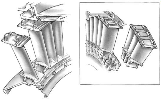
Above: Fig. -14 Typical nozzle guide vanes showing their shape and location.
(Courtesy: Rolls-Royce)

Above: Fig. -15 Various methods of attaching blades to turbine disks. (Courtesy: Rolls-Royce)
Construction
The basic components of the turbine are the combustion discharge nozzles, the nozzle guide vanes, the turbine disks and the turbine blades. The rotating assembly is carried on bearings mounted in the turbine casing and the turbine shaft may be common to the compressor shaft or connected to it by a self-aligning coupling.
Nozzle Guide Vanes
The nozzle guide vanes are of an aerofoil shape with the passage between adjacent vanes forming a convergent duct. The vanes are located in the turbine casing in a manner that allows for expansion ( Fig. -14). The nozzle guide vanes are usually of hollow form and may be cooled by passing compressor delivery air through them to reduce the effects of high thermal stresses and gas loads.
Turbine Disks
Turbine disks are usually manufactured from a machined forging with an integral shaft or with a flange onto which the shaft may be bolted. The disk also has, around its perimeter, provision for the attachment of the turbine blades.
To limit the effect of heat conduction from the turbine blades to the disk a flow of cooling air is passed across both sides of each disk.
Turbine Blades
The turbine blades are of an aerofoil shape designed to provide passages between adjacent blades that give a steady acceleration of the flow up to the "throat", where the area is smallest and the velocity reaches that required at exit to produce the required degree of reaction.
The actual area of each blade cross-section is fixed by the permitted stress in the material used and by the size of any holes which may be required for cooling purposes. High efficiency demands thin trailing edges to the sections, but a compromise has to be made so as to prevent the blades from cracking due to the temperature changes during engine operation.
The method of attaching the blades to the turbine disk is of considerable importance, since the stress in the disk around the fixing or in the blade root has an important bearing on the limiting rim speed. Various methods of blade attachment are shown in Fig. -15; however, the B.M.W. hollow blade and the de Laval bulb root types are not now generally used on gas turbine engines.
A gap exists between the blade tips and casing, which varies in size due to the different rates of expansion and contraction. To reduce the loss of efficiency through gas leakage across the blade tips, a shroud is often fitted. This is made up by a small segment at the tip of each blade which forms a peripheral ring around the blade tips. An abradable lining in the casing may also be used to reduce gas leakage.
Contra-Rotating Turbine
Fig. -16 shows a twelve-stage contra-rotating free power turbine driving a contra-rotating rear fan. This design has only one row of static nozzle guide vanes. The remaining nozzle guide vanes are, in effect, turbine blades attached to a rotating casing which revolves in the opposite direction to a rotating drum. Since all but one aerofoil row extracts energy from the gas stream, contra-rotating turbines are capable of operating at much higher stage loadings than conventional turbines, making them attractive for direct drive applications.
Dual Alloy Disks.
Very high stresses are imposed on the blade root fixing of high work rate turbines, which make conventional methods of blade attachment impractical. A dual alloy disk, or 'blisk' as shown in Fig. -17, has a ring of cast turbine blades bonded to the disk.
Materials
Nozzle Guide Vanes.
Due to their static condition, the nozzle guide vanes don’t endure the same rotational stresses as the turbine blades. Therefore, heat resistance is the property most required. Nickel alloys are used, although cooling is required to prevent melting. Ceramic coatings can enhance the heat resisting properties and, for the same set of conditions, reduce the amount of cooling air required, thus improving engine efficiency.
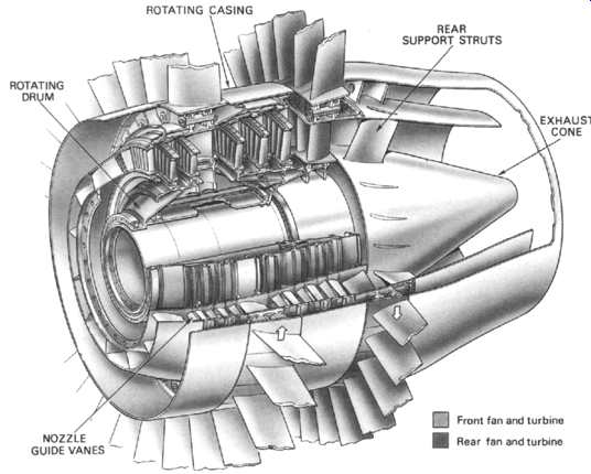
Above: Fig. -16 Free power contra-rotating turbine. (Courtesy: Rolls-Royce)
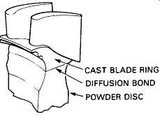
Above: Fig. -17 CAST BLADE RING DIFFUSION BOND POWDER DISC Section through
a dual alloy disk. (Courtesy: Rolls-Royce)
Turbine Disks.
A turbine disk has to rotate at high speed in a relatively cool environment and is subjected to large rotational stresses. The limiting factor which affects the useful disk life is its resistance to fatigue cracking.
In the past, turbine disks have been made in ferritic and austenitic steels but nickel-based alloys are currently used. Increasing the alloying elements in nickel extend the life limits of a disk by increasing fatigue resistance. Alternatively, expensive powder metallurgy disks, which offer an additional 10% in strength, allow faster rotational speeds to be achieved.
Turbine Blades.
A brief mention of some of the points to be considered in connection with turbine blade design will give an idea of the importance of the correct choice of blade material. The blades, while glowing red-hot, must be strong enough to carry the centrifugal loads due to rotation at high speed. A small turbine blade weighing only two ounces may exert a load of over two tons at top speed and it must withstand the high bending loads applied by the gas to produce the many thousands of turbine horse-power necessary to drive the compressor. Turbine blades must also be resistant to fatigue and thermal shock, so that they won’t fail under the influence of high-frequency fluctuations in the gas conditions, and they must also be resistant to corrosion and oxidization. In spite of all these demands, the blades must be made in a material that can be accurately formed and machined by current manufacturing methods.
From the foregoing, it follows that for a particular blade material and an acceptable safe life there is an associated maximum permissible turbine entry temperature and a corresponding maximum engine power. It’s not surprising, therefore, that metallurgists and designers are constantly searching for better turbine blade materials and improved methods of blade cooling.
Over a period of operational time the turbine blades slowly grow in length.
This phenomenon is known as 'creep' and there is a finite useful life limit before failure occurs.
The early materials used were high-temperature steel forgings, but these were rapidly replaced by cast nickel base alloys which give better creep and fatigue properties.
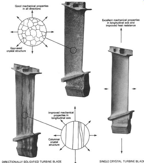
Above: Fig. -18 Various turbine blade crystal structures. (Courtesy: Rolls-Royce)
Close examination of a conventional turbine blade reveals a myriad of crystals that lie in all directions (equi-axed). Improved service life can be obtained by aligning the crystals to form columns along the blade length, produced by a method known as "Directional Solidification". A further advance of this technique is to make the blade out of a single crystal. Examples of these structures are shown in Fig. -18. Each method extends the useful creep life of the blade ( Fig. -19) and in the case of the single crystal blade, the operating temperature can be substantially increased.
Balancing
The balancing of a turbine is an extremely important operation in its assembly. In view of the high rotational speeds and the mass of materials, any unbalance could seriously affect the rotating assembly bearings and engine operation. Balancing is effected on a special balancing machine.
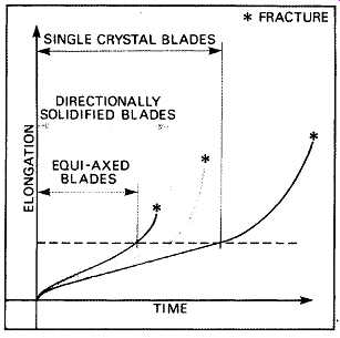
Above: Fig. -19 Comparison of turbine blade life properties. (Courtesy: Rolls-Royce)
Internal Air System
A typical system is discussed below (as used in the Rolls-Royce Avon). To disperse the heat conducted from the main hot gas stream to the turbine, bearings and the internal casings, a flow of cooling air is directed over these components, and this same air supply is used to pressurize various oil and gas seals. Low pressure air from stage 3 of the compressor is used for cooling the main bearings and for pressurizing the oil seals, and is then dispersed to atmosphere.
High pressure air from stage 15 cools the turbine and pressurizes the gas seals before dispersing.
Low Pressure Air.
Air from stage 3 of the compressor is directed into the hollow compressor shaft, and holes at the front of the shaft direct the flow to the rear of the front bearing to pressurize the oil seals and prevent oil leakage into the compressor.
Holes at the rear of the compressor shaft allow some LP air into the area around the rear bearing housing. This air adequately reduces the transfer of heat from the combustion chambers to the turbine shaft and rear bearing, and prevents oil leakage by pressurizing both the center bearing oil seals and the rear beating front oil seal.
The air then flows to the location between the combustion chambers and the exhaust unit, i.e., cooling air manifold, over the nozzle box and turbine casings to the upper part of the manifold and then to atmosphere.
The remainder of the LP cooling air flows through the turbine shaft and outwards to cool the rear beating inner track, then onwards to the cooling air manifold.
Above: Fig. -20 Main intend air system flows. (Courtesy: Rolls-Royce)
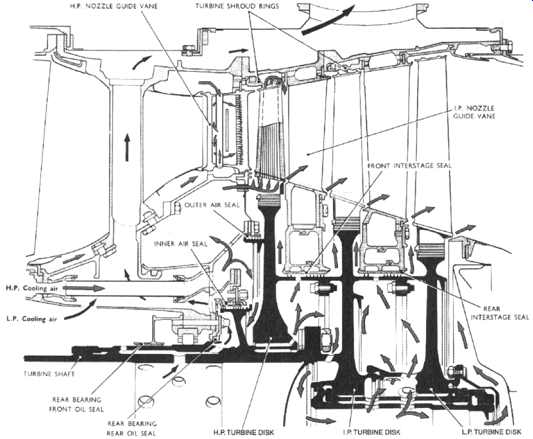
Above: Fig. -21 Air system flow in the turbine. (Courtesy: Rolls-Royce)
High Pressure Air.
Some of the compressor delivery air is directed via the combustion chamber inner heat shield to the front face of the HP turbine disk, after which the flow divides into two main streams.
One air stream enters the annulus formed by the outer air seal carrier and the HP nozzle guide vane inner locating ring. The air passes into the labyrinth seal for pressurizing the gap between the roots of the HP turbine blades and the HP nozzle guide vanes. This air is also used to balance the pressures across the front of the nozzle box and to provide a flow of cooling air for the HP turbine blades (which is a feature of the higher powered Avon gas generators). The air enters the hollow blades via holes in the aerofoil sections, passes out through the blade tips, then flows into the main gas stream through the space at the rear of the rotor blade tip shrouds.
The second air stream flows inwards to pressurize the inner air seal before passing to the area between the turbine HP and IP disks. From there the flow divides, cools the IP and LP disks and exhaust deflection plate, and also pressurizes the gap at the turbine blade root before passing into the main gas stream.
The HP and IP nozzle guide vanes are cooled by high pressure air which is passed through the vanes along the leading and trailing edges, and exhausted via trailing edge drillings. HP air also cools the HP and IP shroud tings, the same supply preventing hot gases passing behind the turbine shrouds.
Burners
The following burner designs have generic features typical for the fuel applications featured. The sketches depict Rolls-Royce Avon configurations.
Liquid Fuel Burners
Liquid fuel is injected at high pressure into the combustion chambers using duplex burners (or fuel injection nozzles). A duplex burner is fitted in each of the eight combustion chambers. Each burner incorporates a primary filter and primary nozzle co-axial with a main nozzle. Additionally an air shroud directs air across the nozzle faces to minimize carbon deposition, and the amount of air flow is controlled between limits to optimize weak burning stability and ignition performance.
The atomized fuels spray from the two nozzles takes the form of a hollow cone, the spray cone angle of the primary being less than that of the main.
Gas Fuel Burners
The gas burners have been designed to simulate as far as possible the conical injection pattern of the liquid fuelled burners, and each burner incorporates a deflector valve and shroud to produce the conical shape.
An alternative pepper-pot burner is available for use with heavier or wet hydrocarbon gases.
Dual Fuel Burners
The dual fuel burner nozzle was developed to enable liquid fuels and gaseous fuels to be used alternatively or at the same time.
While a pressure jet atomizer is used for start purposes, atomization at power conditions is achieved by the airspray principle - the subject of a Rolls-Royce patent in 1952. This method of atomization makes use of the air pressure drop across the flame-tube which is usually about 5% of the compressor outlet pressure. The pressure drop results in an air velocity in the air atomizing duct of around 400 ft/s (122 m/s), and this remains fairly constant over the power range.
Atomization is achieved by the fuel being presented in a thin film to the air, which accelerates the fuel, and in so doing produces drag forces which, acting against surface tension, tear the film into droplets. In the airspray principle, air velocity is most important- and this does not change greatly over a wide range of power settings.
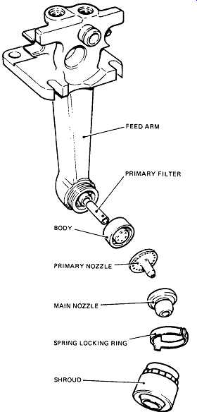
Above: Fig. -22 FEED ARM MARY FILTER PRIMARY NOZZLE -~ MAIN NOZZLE SPRING
LOCKING RING SHROUD Liquid fuel burner. (Courtesy: Rolls-Royce)
SELECTING A GAS TURBINE
At some point in their working life, process engineers may be asked to select or be part of a team for, selecting a gas turbine. The main features to be considered in this process are described below. Items on this list are also a good check list during normal operation, packaging and shipping when major repairs off-site are required, and when modifications are proposed by the manufacturer (to assess the gross effect of those changes). Reference literature used for this subsection was edited from Rolls-Royce literature on their Avon and RB211 models.
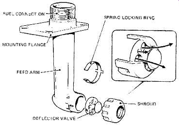
Above: Fig. -23 Gas fuel burner. (Courtesy: Rolls-Royce)
Required Nominal Power Output --See Fig. -25. Also see subsections on growth potential and performance characteristics.
Thermal Efficiency and Cogeneration Potential
Consider if simple cycle application is what is required, or if regeneration, waste heat recovery or combined cycle would benefit overall process profitability (see the appendix on cycles in this section). Optimized cogeneration is responsible operation from both economic and environmental perspectives.
Cogeneration is the utilization of normally wasted gas generator exhaust heat to produce additional energy via a heat recovery system. ( Fig. -26). This conversion of a fuel can supply all the energy requirements of a given building, factory, or process utility at their point of utilization, satisfying the demands of heating, cooling and electrical generation from a single energy source.
The type of fuel used in the gas turbine may be liquid or gaseous, and it’s the factors of cost, availability and transportation which determine the selection of fuel type. The gas turbine is a basic energy converter, and is therefore considered to be the heart of the system. The power turbine drives an a.c. generator or an item of driven equipment such as a compressor.
Exhaust gas from the turbine is directed into an exhaust gas heat exchanger to produce steam or hot water to power a steam turbine or service district heating requirements. Additionally, these products can then be passed through an absorption cycle water chilling package to satisfy air conditioning and other refrigeration applications.
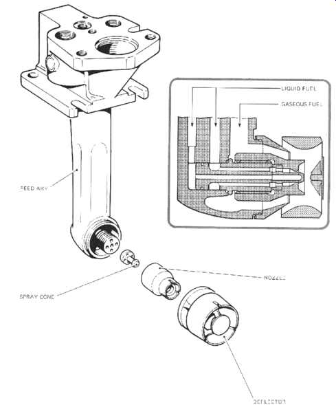
Above: Fig. -24 Dual fuel burner. (Courtesy: Rolls-Royce)

Above: Fig. -25 Nominal power output for mechanical drive and power generation.
(Courtesy: Rolls-Royce)
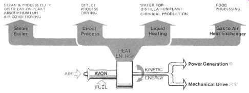
Above: Fig. -26(a) Cogeneration schematic. (Courtesy: Rolls-Royce)
Operational Track Record
Consider this item in terms of running hours for the engine being assessed, and availability and reliability figures for the specific application in question ( Fig. -27).
In pipeline service the Avon has achieved a recorded:
--Availability 99.8%
--Reliability 99.7%
Growth Potential
This is more of a concern for aeroengines. There are, however, genetic industrial gas turbines, usually aeroengine derived that have a design that has growth potential.
This usually means that design development work being conducted will produce options including new components that will fit within the same core diameter as the original engine, which can then be run at a higher power rating. (See TABLE -1, -2 and -3. Also see subsection on performance characteristic.
Start Up and Cool Down
Full power production in a few minutes from cold start is frequently a requirement in a mechanical drive machine that is not base or continually loaded. Long warm up and cool down periods help reduce the effective operating hours used up by the turbine. Proper warm up and cool down are safeguards against shaft bowing, which occurs in older designs.
Engine Material and Design Features
Consider overall engine features in terms of corrosion resistance features such as:
Above: Fig. -26(b) High efficiency cogeneration plant in Rotterdam, The Netherlands.
Up to 90% of the total fuel energy can be used in this type of plant. (Courtesy: Rolls-Royce)
TABLE .1 Industrial Avon: Entry Into Service and Comparative Performance ISO Gas generator types (variants)
Year of entry into service (approx.)
Nominal power output EGHP
Nominal thermal efficiency % (combined gas generator and matched power turbine)
Above: Fig. -27 Data for the Rolls-Royce Avon. (Courtesy: Rolls-Royce)
TABLE .2 Industrial Avon: Gas Generator Variants The Avon has been developed progressively over many years giving incremental power output increases as material and cooling changes allowed. Five Marks of Avon have existed (including the short lived Mk.1535E) and those remaining in service are the Mk.1533, 1534, 1535-120 and the Mk.1535-160.
The gas generator is further identified by a sub-mark number, this being a suffix which identifies whether the lubricating oil, hydraulic oil and fuel system components are mounted on or off the engine itself, i.e. Phase 1 or Phase 2. Phase 2 are served by floor-mounted ancillaries. The chart below gives a useful reference as a means of identifying gas generator types by the suffix number.
Type Phase 1 Phase 2 Phase 1 Phase 2
A close-coupled unit is one which is directly attached to the power turbine, in this case the power turbine is an RT56.
Power output and efficiency improvements are realized with a close-coupled configuration as inlet ducting losses are reclaimed.
(Rolls-Royce Industrial & Marine Gas Turbines Limited)
compressor materials such as titanium alloy selections, ceramic coatings rotor dynamics, such as blade shrouding turbine materials such as alloys for corrosion resistance and creep life flexibility afforded by bleed valve system combustor design fuel flexibility (gas, liquid, dual) internal cooling on turbine blades and nozzle guide vanes
TABLE .3 Industrial Avon Nominal Performance-Mechanical Drive Applications, Imperial Units- ISO Conditions - No Losses (Rolls-Royce Industrial & Marine Gas Turbines Limited
A general specification for a gas turbine will highlight these features, as the outline description for Rolls-Royce RB211 does in Fig. -28.
a. Seven-stage IP compressor Rotor blades ~Titanium alloy Stator blades ~Corrosion resistant alloy steel
b. Six-stage HP compressor Blade materials are chosen for maximum corrosion resistance and cyclic fatigue life at the higher operating temperature for this assembly.
Rotor blades" Stages 1 to 3 Stage 4 Stages 5 and 6 Titanium alloy Corrosion resistant alloy steel Corrosion and heat resistant nickel base alloy
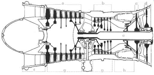
Above: Fig. -28 Schematic of gas turbine. (Courtesy: Rolls-Royce)
Stator blades: Stages 1 to 5 Corrosion resistant alloy steel Stage 6 Corrosion and heat resistant nickel base alloy The steel stator blades on both compressors are ceramic coated to give maximum resistance to corrosion and oxidization.
c. Single-stage lip turbine Nozzle guide vanes and rotor blades are air cooled. Rotor blades are shrouded to ensure that sealing remains good throughout the operating life of the unit and that power and thermal efficiency are maintained at a high level close to the initial pass-off test.
d. Single-stage IP turbine Cooled nozzle guide vanes and shrouded turbine blades.
Blades in both turbines Corrosion resistant nickel base alloys (giving maximum creep life)
e. Rotating assemblies Co-axial drive shafts connect the turbines to the compressors.
f. Inlet guide vanes A single stage of variable incidence inlet guide vanes, in conjunction with bleed valves on both compressors, maintains optimum performance over the whole speed range with the minimum mechanical complexity.
g. Bleed air Bleed valves on the compressors assist low power starting and give good handling characteristics. Bleed ports on the casings provide IP and HP compressor air for power turbine cooling and other services.
h. Combustion Annular combustion chamber with 18 burners. The burners are designed to function with gaseous fuel, distillate liquid fuel, or a mixture of the two, with or without water injection. The annular design of the chamber provides a clean aerodynamic extension to the HP compressor outlet, minimizes the area to be cooled, gives good temperature distribution, and avoids interconnector problems.
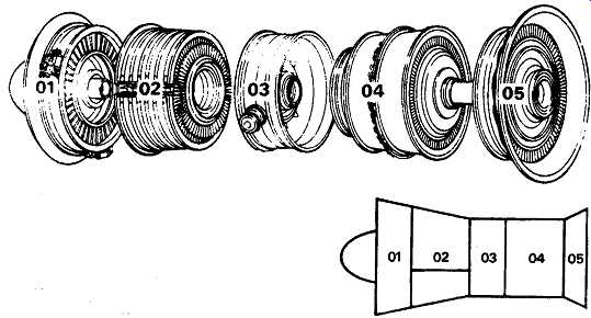
Above: Fig. -29 Modules in gas turbine. (Courtesy: Rolls-Royce)
Modular Construction
This feature is of growing importance in cutting down on maintenance times, reducing how much of the process system around the gas turbine needs to be dismantled for component removal and ease of transport of major modules, especially in remote and offshore applications The gas generator shown in Fig. -29 (a Rolls-Royce RB 211) is constructed from five modules- all fully interchangeable with standard replacements. Modular construction offers the following advantages:
-- Modules may be changed without removal of the gas generator from site.
-- The modules, of low weight and size, are easily transported to remote sites where access may be difficult. All modules, and the complete gas generator, are portable by helicopter.
-- Reduced need for holdings of spare gas generators and range of spare parts.
-- Reduced down-time and maintenance costs. Lower down-time improves plant availability.
-- Life capability of all modules can be maximized with flexibility of inspection intervals.
Bearings
The number of bearings, type of beatings and proximity of beatings to hot section zones, needs to be considered (see Fig. -30). Beatings are positioned away from the hot combustion zone. Main roller bearings are hydraulically damped by a squeeze film ( Fig. -31). The thin film of oil between bearing outer track and bearing housing provides a high degree of damping which:
-- Reduces vibration
-- Increases component life
-- Ensures correct operation of rolling elements of beatings at all loads and shaft speeds
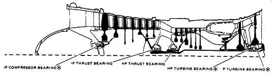
Above: Fig. -30 Bearing positions in a gas turbine. (Courtesy: Rolls-Royce)
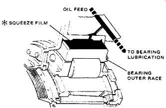
Above: Fig. -31 Squeeze film damped bearing. (Courtesy: Rolls-Royce)
Auxiliary Systems and Packaging Options
Some of the service problems experienced with gas turbines originate with the auxiliary systems on the gas turbine, which might have been made by a subvendor to the original equipment manufacturer (OEM). The packager of the overall system may be the OEM or one of the subvendors. Operational problems that occur with the gas turbine system could originate with one or more of the components indicated in the following line diagrams.
Starting System
The starting system for the RB211 comprises a gas generator-mounted air/gas-driven starter motor (complete with a speed sensing unit), a skid-mounted shut-off valve and pressure regulator, and a control panel.
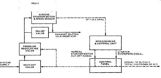
Above: Fig. -32 Starting System Schematic. (Courtesy: Rolls-Royce)
An engine-mounted hydraulic starter can be fitted as an option. Hydraulic power is supplied by the Packager.
The output drive from the starter motor is by a drive-shaft and bevel gear to the HP compressor rotor assembly. Light-up is achieved by energizing two igniter/burners while the HP spool is being turned. The starter drive shaft is automatically disengaged when the gas generator has reached self-sustaining speed.
Speed sensing components are incorporated in the control system to provide safeguards against malfunction. The ability of the starting system to operate successfully in extremely low temperatures is being checked during development testing.
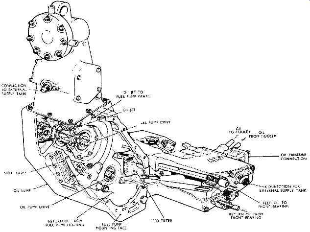
Above: Fig. -33 Phase I oil sump and wheelcase.
Gas Generator Options
In cases like that of the Rolls-Royce Avon, a Phase 1 model with all accessories mounted on the gas generator is available. A Phase II model with these mounted off the gas generator on a separate skid is also available. Both these models are dual fuelled (i.e. they can switch to gas or liquid or a mixture of both these fuels without shutdown).
Phase I. The Phase I Avon gas generator is equipped with gas generator mounted accessories. For example, the oil system, including a combined sump and tank, pressure and scavenge pumps and filter, are all contained in a wheelcase ( Fig. -33). This wheelcase, although having the facility of being removable, forms an integral part of the Phase I gas generator. Similarly, on the liquid fuelled Phase I gas generator, the fuel control system is gas generator mounted, together with such items as the high pressure (HP) fuel pump, HP shut-off cock, pressurizing valve, fuel manifold, burners and piping - all being supplied by Rolls-Royce, with a minimum of equipment being supplied by the purchaser.
The compressor airflow control system can be gas generator mounted and hydraulically powered by the HP fuel pump.
Phase II. The Phase II Avon gas generator has the entire hydraulic and lubricating oil pressure supply and scavenge systems, together with the fuel supply and control system mounted off the gas generator. All these systems will generally be supplied and equipped predominantly with floor/pedestal mounted accessories provided by the purchaser ( Fig. -34 and 35).
===
AND ANTI-ICING AIR MANIFOLD FRONT BEARING HOUSING COMPRESSOR STAGE 7 COMBUSTION BLEED VALVE AIR CASING ANTI-ICING \ ~ AIR VALVE FILTER AND FUEL PRESSURISING VALVE COMPRESSOR OUTLET CASING NOZZ LE BO X AN D TURBINE HOUSING EXHAUST UNIT COOLING AIR OUTLET THERMOCOUPLE HARNESS CONNECTION
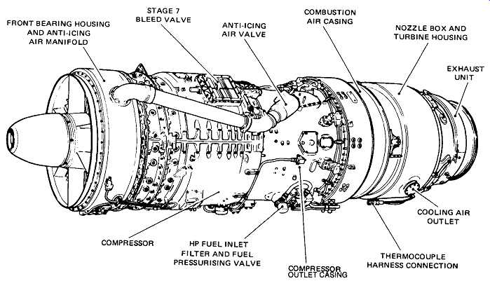
Above: Fig. -34(a) Phase H liquid fuelled (left-hand view). (Courtesy: Rolls-Royce)
===
REAR MOUNTI NG FRONT SUSPENSION TRUNNION / / THERMOCOUPLES / ELECTRO MAGNETIC
/ STAGE 4 BLEED VALVE / LUBRICATING OIL COMPRESSOR AIRFLOW CONNECTION BLOCK
CONTROL MECHANISM
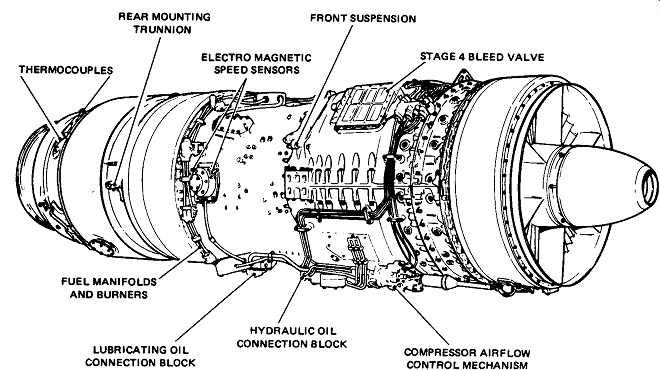
Above: Fig. -34(b) Phase H liquid fuelled (right-hand view).
(Courtesy: Rolls-Royce)
===
FRONT BEARING HOUSING STAGE 7 ANTI-ICING COMBUSTION NOZZLE BOX AND ANTI-ICING AIR MANIFOLD BLEED VALVE AIR VALVE AIR CASING AND TURBINE HOUSING EXHAUST; THERMOCOUPLE COMPRESSOR FUEL MANIFOLD COMPRESSOR INLET OUTLET CASI NG Dual fuelled HP FUEL INLET FILTER J ~.I" LIQUID FUEL PRESSURISING VALVE MANIFOLD PURGE VALVE LIQUID FUEL MANIFOLDS DUAL FUEL BURNERS
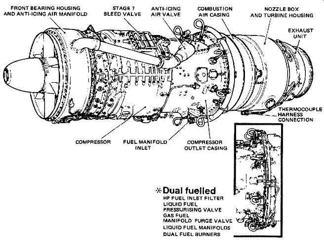
Above: Fig. -35(a) Phase H gaseous fuelled (left-hand view). (Courtesy: Rolls-Royce)
===
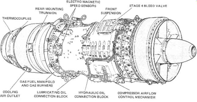
Above: Fig. -35(b) Phase II gaseous fuelled (right-hand view). (Courtesy: Rolls-Royce)
===
Normally the purchaser is responsible for supplying the entire gas generator fuel system up to the gas generator liquid HP fuel and gas fuel inlets.
All Phase I and Phase II Avon gas generators have electromagnetic pick-ups for speed monitoring purposes. Exhaust gas thermocouples are also supplied.
In the case of gaseous and dual fuelled Phase I gas generators, it’s generally the purchaser who supplies the fuel control and forwarding system, with only the fuel manifolds, burners and engine piping being supplied by Rolls-Royce. The compressor air flow control system remains gas generator mounted and is normally powered by a Rolls-Royce supplied hydraulic pump which is fitted in place of the gas-generator-mounted HP fuel pump. Dual fuelled gas generators are also supplied with the liquid fuel pressurizing valve, HP fuel inlet filter and where appropriate the gas fuel manifold purge valve. Those parts of the systems which will be supplied on the Phase II gas generator by Rolls-Royce are: Hydraulic supply system:
-- Compressor air flow control system, disconnect block, and interconnecting pipes.
Lubricating oil system:
-- Lubricating oil (pressure and scavenge) connection block, including magnetic chip detectors in each beating scavenge line, and oil inlet pressure tapping.
-- Associated pipework for bearing feed, scavenge and venting.
Fuel system (liquid fuelled):
-- Fuel pressuring valve
-- Fuel manifold
-- Burners
Fuel system (gaseous fuelled):
-- Fuel manifold
-- Burners
Fuel system (dual fuelled):
-- Liquid fuel pressurizing valve
-- Liquid fuel manifold
-- Gas fuel manifold
-- Gas manifold purge valve
-- Dual fuel burners
Fuel Supply and Control Systems
Liquid Fuelled Phase I Gas Generators
The gas generator fuel system (see Fig. -36) provides a means of forwarding the fuel from the plant fuel system installation to the gas generator.
====
L.P. FIJEL PRESSUHI: REGULATING VALVE; FLOW METER L.P. FUEL. ISOLATING VALVE GAS GENERATOR PURCHASER FUEL CONTHOL SYSTFM GAS GENERATOR EXHAUST GAS TEMPER ATU RE (CONTROL! THERMOCOUPLES FCT CC ~ITROI I FR POWER TURBINE FUEL DELIVERY LINE FILTER LIQUID FULE SUPPLY A -- L.P. FUEL FILTER, H.P. FUEL PUMP AND H.P. FUEL SHUT-OFF COCK B -- FUEL CONTROL SYSTEM INCLUDING COMBINED THROTTLE/H.P. FUEL SHUT-OFF COCK C -- PRESSURIZING VALVE D -- INTAKE GUIDE VANE AND BLEED VALVE RAMS
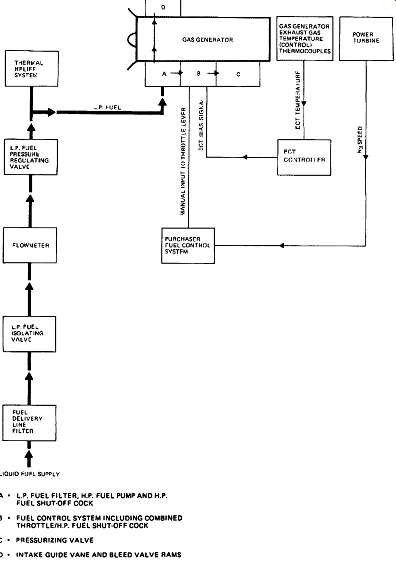
Above: Fig. -36 Liquid fuelled phase I gas generator schematic. (Courtesy: Rolls-Royce)
====
The gas generator fuel control system is designed to satisfy the following basic requirements:
-- Full control of the gas generator at any power level while protecting it from damage should a malfunction occur
-- Control of fuel delivery according to engine demand
-- Shaft speed control
-- Control of fuel flow during rapid acceleration
-- Prevention of flame failure during rapid deceleration
-- Protection against sensor failure
-- Efficient burning of fuel
-- Control of fuel flow during a start
-- Maximum power limitation
-- Control mode indication
-- Stopping the gas generator
Dual Fuelled Gas Generators
The gas generator fuel system (see Fig. -37) provides a means of forwarding the fuel from the plant fuel system installation to the gas generator.
The gas generator fuel control system is again designed to satisfy the following basic requirements:
-- Full control of the gas generator at any power level while protecting it from damage should a malfunction occur
-- Control of fuel delivery according to engine demand
-- Shaft speed control
-- Maximum gas temperature limitation
-- Control of fuel flow during rapid acceleration
-- Prevention of flame failure during rapid deceleration
-- Protection against sensor failure
-- Efficient burning of fuel
-- Control of fuel flow during a start
-- Maximum power limitation
-- Control mode indication
-- Stopping the gas generator
===
LIQUID SUPPLY 1 TO BURNERS J PRESSURE VALVE -- POWER TURBINE SPEED COMPRESSOR DELIVERY AIR (N31 IJ IP2I EXHAUST GAS TEMPERATURE LP COMPRESSOR SPEED IN1)
--LIQUID FLOW CONTROL UNIT -- LIQUID; METERING ~ ACTUATOR ; --VALVE -- = HP F I LTER SPILL--TO BURNERS PRESSURISING RELIEF VALVE (ECT) AMBIENT TEMPERATURE SENSOR (T1] ELECTRONIC CONTROL UNIT POWER INPUT HYDRAULIC POWER PACK -- POWER INPUT TO ATMOSPHERE GAS FLOW CONTROL UNIT GAS -- ACTUATOR - METERING VALVE GAS SHUT-OFF COCK VENT VALVE TO ATMOSPHERE 3-WAY SOLENOID VALVE GAS REGULATING VALVE GAS-SUPPLY
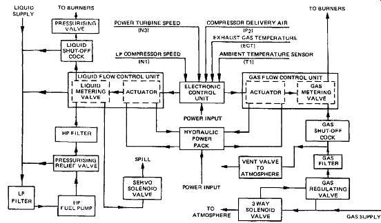
Above: Fig. -37 Dual fuelled gas generator schematic. (Courtesy: Rolls-Royce)
===
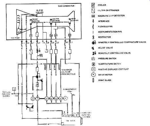
Lubrication and Hydraulic Oil Supply
Liquid fuelled Phase I gas generators
As shown in Fig. -38, the lubricating oil system, incorporates a combined sump and tank, the pressure and scavenge pumps and filters. It’s situated within the wheelcase to form an integral part of the gas generator.
Oil is pumped from the sump to an externally mounted cooler, from where it’s returned to a pressure filter integral with the sump and wheelcase. From there it’s piped to the main bearings and returned via the scavenge pumps and filters to the sump. A gas generator mounted fuel cooled oil cooler is available for liquid fuelled engines, if required, to replace the contractor-supplied external cooler.
Each main shaft beating is protected by a thread-type filter, and each bearing housing incorporates air pressurized seals to retain the oil in the system. The wheelcase and bearings are vented to atmosphere through a breather with a centrifugal separator to minimize oil vapor loss.
For continuous industrial duties, and on gas generators intended to operate by remote control, provision is made for a contractor-supplied auxiliary oil tank to be fitted in addition to the engine mounted tank. This tank is vented to the engine tank and must be provided with its own level checking arrangements.
The Phase I liquid fuelled gas generator takes its hydraulic supply from the gas-generator-mounted HP fuel pump. A high pressure tapping is taken from the pump outlet to supply hydraulic power to actuate the compressor airflow control system.
===
An alternative to the L8 connection Is a Rolls-Royce supplied gas generator mounted pressure switch COOLER FILTER OR STRAINER INTERFACE It FLEXIBLE PIPE RELIEF VALVE PRESSURE -- POSITIVE DISPLACEMENT PUMP ; SIGHT GLASS
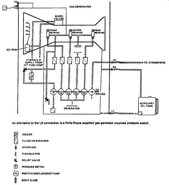
Above: Fig. -38 Liquid fuelled Phase I gas generator schematic for lubrication
and hydraulic oil schematic.
===
FILTER OR STRAINER; INTERFACE FLEXIBLE PIPE / INSTRUMENTATION; REMOTELY CONTROLLED TEMPERATURE VALVE RELIEF VALVE PRESSURE SWITCH TEMPERATURE SWITCH O OSITIVE DISPLACEMENT PUMP SIGHT GLASS
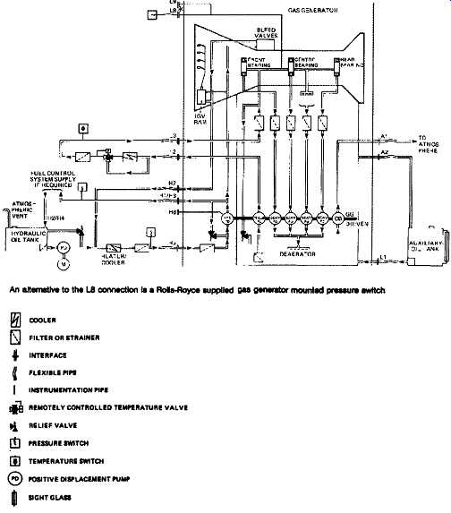
Above: Fig. -39 gaseous and dual fuelled Phase I gas generator lubrication
and hydraulic schematic.
===
Gaseous and Dual Fuelled Phase I Gas Generators
As with the oil system of the liquid fuelled Phase I gas generators, the lubricating oil system for the above generators is self-contained on the gas generator - but with the addition of a supplementary oil tank, an external oil cooler, temperature control valve and pressure filter ( Fig. -39). Depending upon the type of fuel control system selected, a separate hydraulic oil supply is required to operate the compressor airflow control system. The compressor airflow control system remains gas generator mounted and is normally powered by a Rolls-Royce supplied hydraulic pump which is fitted in place of the gas-generator-mounted high pressure fuel pump.
All items not in the Rolls-Royce extent of supply must be designed to meet the requirements outlined in the Rolls-Royce Installation Manual.
Phase II Gas Generators
For Phase II gas generators ( Fig. -40) the scavenge and lubricating oil supply system components (with the exception of the lubricating oil connection block, including magnetic chip detectors in each beating scavenge line, and oil inlet pressure tapping, together with associated pipework for bearing feed scavenge and venting) are removed from the gas generator. The main contractor takes the responsibility of supplying the remote mounted pumps, tanks, cooler and filters.
All Phase II gas generators require a complete off-gas generator hydraulic supply system, including a high pressure hydraulic pump and drive motor. Again it’s the responsibility of the main contractor to supply (apart from the compressor air flow control system, disconnect block, and interconnecting pipes), the high pressure hydraulic pump and drive motor, storage tank, cooler, heater (if required), filter, pressure relief valve, and interconnecting pipework and wiring.
All items not in the Rolls-Royce extent of supply must be designed to meet the requirements outlined in the Rolls-Royce Installation Manual.
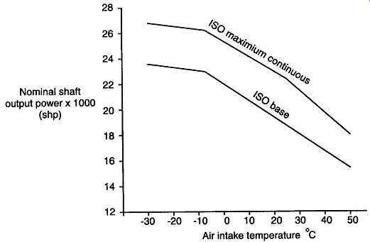
Performance Characteristics
This item becomes particularly important in cases where power output at specific inlet temperature ranges is critical. Note that corrections for altitude affect developed horsepower considerably. (See Fig. -41 and subsection on growth potential.)
Above: Fig. -40 Phase H gas generator, lubrication and hydraulic schematic.
(Courtesy: Rolls-Royce)
TABLE .4 The Effective Swallowing Capacities for Power Turbine/Gas Generator Matches
Gas Generator and Power Turbine Matching
The operation of the gas generator is intrinsically linked with the power turbine it’s driving. The gas generator working conditions are determined by the power turbine effective swallowing capacity. The power turbine capacity directly affects the power output available. Consequently, to achieve the outputs and s.f.c's quoted, it’s essential that the gas generator is operated with a power turbine of the correct specific capacity at the design conditions.
For retrofit situations, any gas generator may be operated into any power turbine by customer choice, and performance details for these combinations may be obtained from the manufacturer.
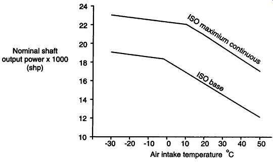
Above: Fig. -41 Performance characteristics of the industrial Avon. (a) Coberra
2348 Avon 1533/RT48 Variation of nominal shaft power with air intake temperature.
No losses, gaseous fuel, sea level operation. (Courtesy: Rolls-Royce) Air intake temperature
~ Nominal shaft output power x 1000 (shp)
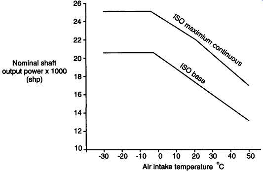
Above: Fig. -41 (b) Coberra 2448 Avon 1534/RT48 Variation of nominal
shaft power with air intake temperature. No losses, gaseous fuel, sea level
operation. (Courtesy: Rolls-Royce)
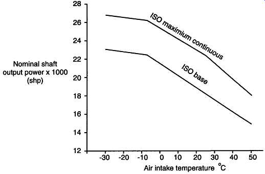
Above: Fig. -41(c) Coberra 2558 Avon 1535-120/RT48 Variation of nominal shaft
power with air intake temperature. No losses, gaseous fuel, sea level operation.
(Courtesy: Rolls-Royce)
Above: Fig. -41 (d) Coberra 2648 Avon 1535-160/RT48S Variation of nominal
shaft power with air intake temperature. No losses, gaseous fuel, sea level
operation. (Courtesy: Rolls-Royce)
Fig. -41(e) Coberra 2348 Avon 1533/RT48 Variation of nominal overall
thermal efficiency with shaft horsepower. (Courtesy: Rolls-Royce)
Fig. -41(f) Coberra 2448 Avon 1534/RT48 Variation of nominal overall
thermal efficiency with shaft horsepower. (Courtesy: Rolls-Royce)
Fig. -41 (g) Coberra 2548 Avon 1535-120/RT48 Variation of nominal
overall thermal efficiency with shaft horsepower. (Courtesy: Rolls-Royce)
Fig. -41(h) Coberra 2648 Avon 1535-160/RT48S Variation of nominal
overall thermal efficiency with shaft horsepower. (Courtesy: Rolls-Royce)
Condition Monitoring and Maintenance Features
"On condition" is the preferred operating mode for gas turbines today. Modular design helps the operator take advantage of this feature. The fact that aircraft engine technology as developed by manufactures like Rolls-Royce, General Electric and Pratt & Whitney is transferred directly into industrial models, accentuate the trends towards modularized construction and on condition maintenance.
The object of condition monitoring is to achieve maximum economic installed life by the identification of evidence of deterioration of the gas generator, or one of its modules, at an early stage.
By the recording and analyzing of the trend of changes in the values of the gas generator running parameters, evidence of deterioration can be identified sufficiently early to allow for planned maintenance. This procedure thus reduces unplanned non-availability of plant, minimizes inconvenience and offers cost savings.
Mechanical Monitoring
This consists of monitoring:
-- Vibration levels ( Fig. -42)
-- Hydraulic and lubricating oil pressures
-- Metal wear (via magnetic chip detectors, Fig. -42)
-- Oil consumption and acidity.
Performance Monitoring
This consists of monitoring:
-- Variable inlet guide vane angle
-- Exhaust gas temperature
-- Exhaust gas pressure
-- IP spool speed
-- HP spool speed.
Borescope Inspection
Borescope inspections ( Fig. -43) can be carried out when trend analysis (as the result of performance monitoring), external examination, or running symptoms, suggest the possibility of internal damage or deterioration.
A number of borescope access ports are located on the gas turbine to facilitate examination of all rotating blades in the compressor and turbine assemblies. Static compressor blades. HP turbine nozzle guide vanes, the combustion chamber liners, and the fuel burners can also be inspected. The time required to conduct an examination is determined by the nature of the inspection. For example, inspection of the IP compressor inlet and outlet blades for suspected damage from a foreign object, could be expected to take 30 minutes.
===
Vibration transducer
OILSCAVENGE BLOCK
Magnetic chip detectors
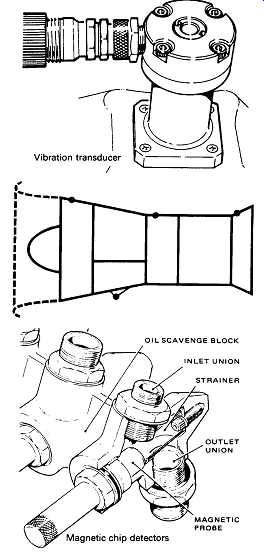
Above: Fig. -42 Typical positions of vibration transducer and magnetic chip
detectors.
===
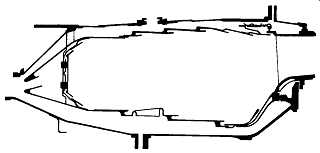
Above: Fig. .43(a) Borescope inspection ports on combustion chamber. (Courtesy: Rolls-Royce)
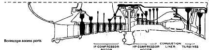
Above: Fig. -43(b) Borescope access ports on gas turbine. (Courtesy: Rolls-Royce)
Routine Servicing
Gas turbines that run reliably on minimum routine servicing requirements have an advantage over those with more time consuming requirements, particularly in applications where continuous running is critical.
Gas generators require to periodic inspection, maintenance and reconditioning to maintain maximum performance. The length of time before some form of reconditioning is required depends on such factors as:
-- Type and cleanliness of fuel
-- Operating environment
-- Efficiency of air filtration
-- Power output
-- Number and frequency of starts
It’s important that a servicing routine is established appropriate to the operation and duty to which the unit is applied. Servicing intervals may be varied as experience and unit accessibility allow, and should be increased in frequency if any adverse operating condition manifests itself. Occasional checks of the integrity of the unit should be made coveting security of equipment, evidence of leaks, and deterioration or wear of components. Initially a weekly schedule may be recommended, but the frequency can be reduced as satisfactory operation proceeds.
Lubricating oil levels, and fuel oil filters should be checked at appropriate intervals depending on the particular installation and its mode of operation. Inspection of magnetic chip detectors, which may be carried out with the unit in operation, forms an important part of the condition monitoring routine for the gas generator. Chip detectors should be inspected frequently during commissioning and at any time when there is evidence of unit deterioration. During normal operation, an infrequent check, for example monthly, should suffice as long as there is evidence of satisfactory operation of the units.
Weekly Checks
Examination of external pipework, conduit and electrical leads
Check lubricating oil tank level
15 min 5 min
Monthly Inspections
Examine air intake flare, VIGVs and visible compressor blades
Inspect magnetic chip detectors
20 min 5 min
Six-Monthly/Annually Inspections
Inspect filters 15 min
Borescope inspection of internal components 7 hours
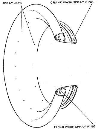
Above: Fig. -44 Location of compressor wash system. (Courtesy: Rolls-Royce)
Compressor Cleaning
Gas generators will often be operated in an atmosphere of fog, industrial pollution or high salt concentrations. Contamination of the compressor in these conditions, if allowed to go unchecked, will result in a loss of compressor efficiency leading to a reduction in gas generator performance. The effects of this contamination can be offset by compressor cleaning at regular intervals or when a deterioration in performance becomes apparent. The compressor can be cleaned by either of the following methods:
-- Crank/soak washing
This method is used when operating conditions permit the gas generator to be shut down for cleaning
-- Fired fluid washing
For occasions when it’s inconvenient to shut down the gas generator
Environmental Considerations
This facet of gas turbine design, operation and maintenance has grown immensely since the release of the first edition of this book. From vague regulatory restrictions that some "green person" on staff came around to check on, it’s fast becoming part of the process and the rotating machinery engineer's daily bread. Those who ignore this trend risk major unnecessary and additional expenditure further down their plants' operating lives.
What follows is a description of low NOx burners. There is considerably more material on this aspect, including details of other low NOx burner designs, as well as NOx reduction techniques such as water injection, low temperature gas turbine designs (that affect NOx production rates), ability to burn lower grade fuels (such as residual fuel), in Environmental Engineering and Management: Sustainable Development in the Power Generation, Oil & Gas and Process Plant Industries (Butterworth-Heinemann, 1998)
Low NOx Burners
Present nitrogen oxide (NOx) emission limits for gas turbines in Japan and the United States (notably California) can hardly be satisfied with commonly used NOx abatement techniques. Although the 75 ppm, 15% oxygen EPA bench-mark value is the prevailing US Federal standard, new projects now call for Best Available Control Technology (BACT) or specify an overall limit of < 25 ppm. Before investing in new plant equipment, operators of power plants must seriously consider the public's interest in having ecologically-clean as well as economically-sound power plants.
Similar trends are now emerging in Europe and with the increasing environmental awareness in the industrial nations it may not be long before a < 40 ppm limit is imposed throughout Western Europe.
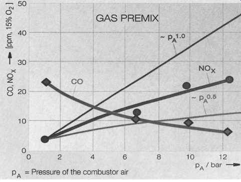
Reducing harmful pollutants in the process of burning fossil fuel is a compromise: reducing carbon monoxide (CO) normally results in increased output of harmful NOx and vice versa. Whereas CO is very poisonous, NOx can cause acid rain and, in combination with sunlight, increase ground-level ozone to unhealthy values. Carbon dioxide (CO2) is another unwelcome pollutant; as some scientists believe, it can be a contributor to global warming. In addition, limited fossil fuel resources should be used as efficiently as possible - and this calls for an economical technology.
In the past, steam or water injection was the most widely used method for NOx reduction. The drawback of this method lies in its efficiency loss (when injecting water) and in its increased costs, arising from the injection water treatment. Selective Catalytic Reduction (SCR), a further NOx reduction method, leads to even higher operating costs and lower efficiency.
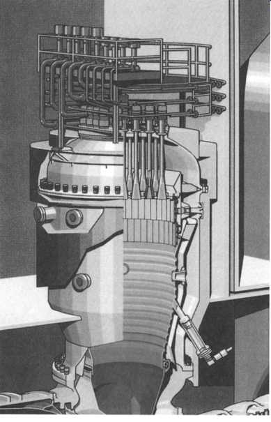
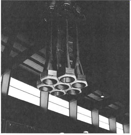
ABB now presents an ecological as well as economical solution to the problem, by introducing a new dual fuel dry low-NOx burner which is designed to meet NOx emission limits down to 9 ppm on natural gas- without steam injection or SCR. A pragmatic approach combining theory, experimentation, and intuition resulted in a remarkably simple and efficient device: the double cone burner, also called EV-burner ( Fig. -45). The EV-burner- the result of research started in 1987 - is the latest step in ABB's development program. Rather than just concentrating on ever lower NOx levels, ABB has chosen a total solution that limits pollutants and at the same time increases energy efficiency. The "environmental" (EV) burner delivers NOx levels lower than 15 ppm, a value considered unrealistic in dry combustion only a short time ago. When gas is burned, ABB can guarantee 25 ppm dry, while 42 ppm can be achieved burning oil, with water injection. Years of research into new combustor technologies and extensive test programs have led to a system that also yields particularly low emission values for carbon monoxide (CO) and unburnt hydrocarbons (UHC). ABB's new EV-burner is cleaner and more efficient than the company's conventional burners, while being reliable and safe due to its simple design.
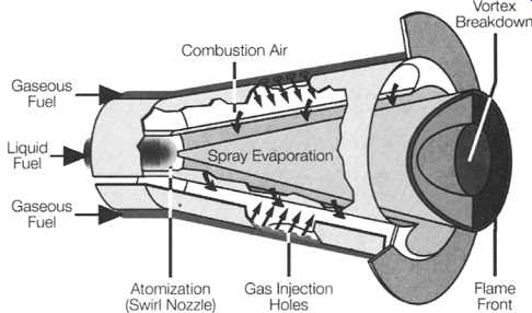
Operating Principle. The EV-burner is a dual fuel burner, this means that it can be operated on gaseous fuel, on liquid fuel, or in dual fuel operation.
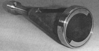
The burner is shaped like two half-cones (400 mm long, 150 mm in diameter)
slightly offset sideways to form two inlet slots of constant width running the full length, ( Fig. -46). Combustion air enters the cone through these slots and gas is injected through a series of fine holes in their edges. With this arrangement fuel and air are intimately mixed ( Fig. -47).
Above: Fig. -45 Dual fuel double cone burner. (ABB, Sweden)
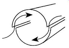
Above: Fig. -46 Two half-cones, forming two inlet slots. (ABB, Sweden)
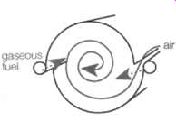
Above: Fig. -47 Fuel and air are mixed at the inlet slots. (ABB, Sweden)
Above: Fig. .48 EV-silo combustor. (ABB, Sweden)
Above: Fig. -49 Annular combustor of the GT13E2. (ABB, Sweden)
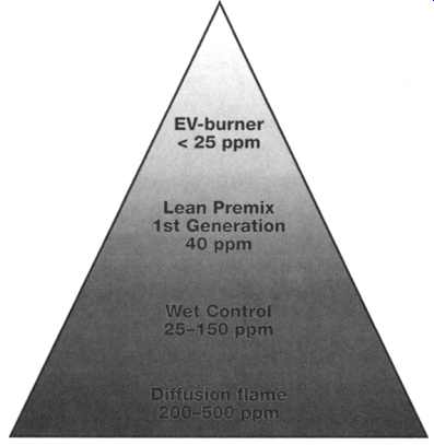
Above: Fig. -50 Development of the dry low-NOx burner. (ABB, Sweden)
Above: Fig. -51 First-generation premix burner. (ABB, Sweden)
Above: Fig. -52 Assembly of the EV-burner. (ABB, Sweden)
Above: Fig. -53 The EV-burner, designed to provide low NOx emission and high
fuel efficiency. (ABB, Sweden)
Above: Fig. -54 Emissions measured for a given fuel to air ratio. (ABB, Sweden)
The liquid fuels are sprayed into the cone through an atomizing nozzle. The combustion air enters the cone in the usual way, where it’s mixed with the vaporized fuel. Water injection can also be applied.
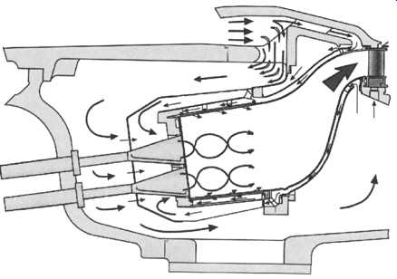
The design of the EV-burner is based on the vortex breakdown principle: A lean mixture leaves the cone and enters the flame. At the exit of the burner the vortex breaks down, forming a recirculation zone which stabilizes the flame in free space, keeping combustion temperatures and emissions low.
As there is no flameholder body exposed to ignitable mixtures, and no danger of any flashback damaging the burner, it’s a very reliable and safe design.
Excess air is a feature of the EV-burner design, resulting in a flame temperature around 500 ~ lower than in a conventional burner and in a very low NOx level.
Applications. In the combustor there is no other burning mode than premix combustion. A group of burners act as a pilot system for all burners.
The EV- burner is suited to both annular combustion chambers and to standard silo combustors ( Fig. -48) and it can be fitted to all of the company's gas turbine models. Existing units working with ABB's conventional burners can be retrofitted with EV- burners.
EV silo combustors are equipped with 19-54 burners (number of burners depending on gas turbine type) and achieve NOx emission values below 25 ppm with natural gas.
The EV- burner can be fitted to the annular combustion system of the 24 MW GT10 turbine ( Fig. -49)
Another application is with ABB's latest heavy-duty gas turbine of the proven GT13 family; the combustion chamber on the GT13E2 is of the single annular type, with 72 burners arranged symmetrically around the annulus in four rows. With natural gas, the NOx value is well below 25 ppm.
Development History
As the formation of nitrogen oxides in the process depends both on the firing temperature and the residence time of the fuel/air mixture in the combustion zone, conventional burners produce high amounts of NOx. By injecting water directly into the flame, it’s possible to lower the temperature and thus reduce NOx emission to levels of 25-75 ppm. This traditional method of lowering NOx produced in gas turbines is used widely throughout the world. But this "wet" combustion process also considerably lowers energy efficiency, increases the output of CO due to incomplete combustion, uses large amounts of water, and causes higher maintenance costs.
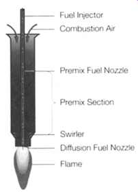
Development of the Dry Low-NOx Emission Techniques. ABB's approach to this problem was the development of the dry low-NOx burner. The design and development history ( Fig. -50) leads from ABB's conventional diffusion burner to the advanced EV- burner, covering various evolution phases- starting with the first-generation lean premix burner ( Fig. -51).
Its concept is based on the simple principle of premixing air and fuel, with the maximum amount of excess air, before combustion. One burner consists of a premixing section, a separate combustion zone and a solid flame holder.
The temperature of the flame is determined by the homogeneity of the air/fuel mixture and the amount of excess air in the combustion. About twice the theoretical amount of air required for combustion is used- thus giving the method its name "lean premix". The flame temperature is at least 500 ~ lower than in the company's regular diffusion burner design and therefore NOx emission is reduced to 40-60 ppm.
First commercial operation of these dry low-NOx burners occurred in 1984 on a Type 13 gas turbine, when the turbine's diffusion burner was replaced by a bundle of lean premix burners.
The first-generation lean premix burners need careful monitoring and often use diffusion or pilot flames against combustion instabilities.
Assembly of the EV- burner is illustrated in Fig. -52. A photograph of the EV-burner is illustrated in Fig. -53. Fig. -54 shows emissions measured for a given fuel to air ratio.
Prev.: Gear Speed Transmission
Equipment | Next: Gas
Turbine Cycles / Life Cycle Usage / Specific Maintenance Inspections
Home top
of page