AMAZON multi-meters discounts AMAZON oscilloscope discounts
In numerous types of process machinery, gears are employed to transmit motion and power from one revolving shaft to another or from a revolving shaft to a reciprocating element. When used between revolving shafts, the shafts can take one of only three positions: they may be parallel, may intersect at an angle, or may cross without intersecting. If the shafts are parallel, the basic friction wheels and the gears developed from them assume the shape of cylinders ( Fig. -1 and -2). When the shafts are not parallel, the shapes of the friction wheels and gears will be different. For example, on intersecting shafts the wheels become cones and the gears developed on these conical surfaces are called bevel gears ( Fig. -3). Where motion is transmitted from a shaft to a reciprocating element, a cylindrical friction wheel may engage a flat surface, and the gears assume a similar form ( Fig. -4). All of these methods of transmitting power between cylinders, cones, and flat surfaces involve rolling motion. When shafts cross (one above the other), the friction wheels may be cylindrical or may be of hyperbolic cross section. The gears developed on these surfaces are helical ( Fig. -5) or hypoid ( Fig. -6). In neither case will there be pure rolling action, because when shafts are crossed there is unavoidable side-slip between the surfaces of the wheels.
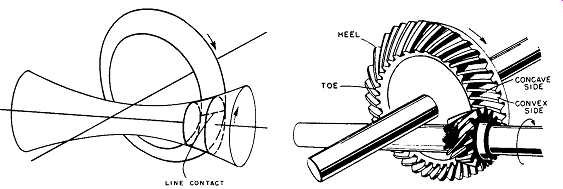
It’s important to appreciate that the type of contact that occurs between the surfaces of friction wheels will also be the type of contact that will occur between the meshing teeth of the corresponding gears. Thus the contact between two cylinders on parallel shafts takes place along a line, and the contact between the teeth developed on those surfaces ( Fig. -2) also occurs along a line. Likewise, the contact between two cones and the teeth developed on those cones ( Fig. -3) will occur along lines. The same condition exists on hypoid gears. However, the contact between friction surfaces is not always a line. Where cylindrical surfaces are on crossed, nonintersecting shafts ( Fig. -5), contact occurs at a point instead of along a line. When this is the case, the teeth developed on these surfaces also make point contact.
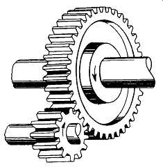
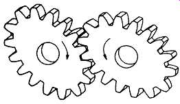
Above: Fig. -1 Typical external spur gear set. (Prager, Inc., New Orleans,
LA.)
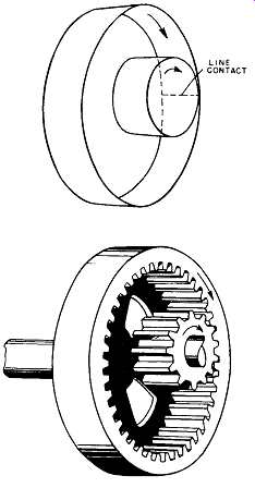
Above: Fig. -2 Internal spur gears. The pitch surfaces on friction wheels
contact along a line (upper view) to transmit motion between parallel shafts.
The teeth are developed on internal and external cylindrical pitch surfaces
as shown in the lower view. LINE CONTACT (Prager, Inc., New Orleans, LA.)
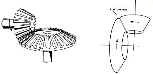
Above: Fig. -3 Bevel gears. These shafts intersect at a right angle, although
bevel gears may also be used between shafts that intersect at larger or smaller
angles. (Prager, Inc., New Orleans, LA.)
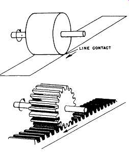
Above: Fig. -4 Rack-and-pinion gear set. (Prager, Inc., New Orleans, LA.)
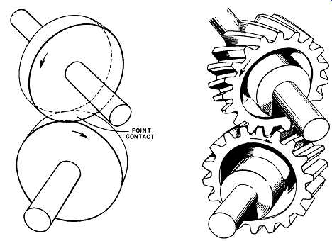
Above: Fig. -5 Principle of helical gearing. (Prager, Inc., New Orleans,
LA.)
Above: Fig. -6 Elliptical gears as occasionally used in special machinery.
(Prager, Inc., New Orleans, LA.)
Above: Fig. -7 Equalizer gear with eccentric pinion. (Prager, Inc., New Orleans,
LA.)
Above: Fig. -8 Stop-motion or intermittent gearing. (Prager, Inc., New Orleans,
LA.)
Above: Fig. -9 Epicyclic, or planetary gearing. (Prager, Inc., New Orleans,
LA.)
TYPES OF GEARS
Spur Gears
When the shafts are parallel, the teeth of the meshing gears may be cut straight across the faces of the gear blanks ( Fig. -1). Gears of this kind are called spur gears. There are many special kinds of spur gears, some of which are not commonly encountered. Although none of these special forms differ materially in tooth action from the usual spur gears, it may be beneficial to mention some of them that are sometimes found in special applications.
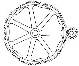
A spur gear meshing with a straight element ( Fig. -4) is known as a rack and pinion. The rack may be visualized as a short section of an infinitely large spur gear; a gear so large in diameter that the teeth lie on a straight line. Elliptical gears ( Fig. -6) are used to convert the uniform rotary motion of a driving shaft to a rhythmic, pulsating rotation of the driven shaft. An equalizer gear and eccentric pinion ( Fig. -7) are sometimes used to drive large chain conveyors in order to prevent the changes of conveyor speed that would occur when the long bar links pass around the sprockets at the driving end. The eccentric driving pinion revolves at a constant speed, but it imparts an irregular motion to the equalizer gear that is calculated to provide a smooth, unvarying speed to the chains. This type of drive reduces what otherwise might be excessive shock on the chains. Another special type of spur gear is sometimes encountered in what are known as stop motion or intermittent gears ( Fig. -8). In this modification, the driving gear rotates continuously but actuates the driven gear only when the teeth of both gears are engaged. At other times, the driven gear is locked in a fixed position.
Ordinary gears are sometimes used in special groupings; For example, the epicyclic or planetary arrangement of gears in Fig. -9 makes possible a very compact reduction gear set. Such a unit usually consists of a central pinion, several planetary gears mounted on a spider, and an internal gear (ring gear) encircling the entire unit. One of the three elements - pinion, spider, or ring gear- must be held stationary, the other two then being used as power input and output elements.
Usually it’s the ring gear that is rigidly fixed in the housing of the gear set. The pinion is usually the driving element with the spider the power take off, that is, the driven element. In this arrangement, the driving and driven shafts are in line with each other and rotate in the same direction but at different speeds.
Epicyclic gearing is often the ideal solution for transmitting high horsepower at high speeds where a compact, in-line, and lightweight drive unit is required.
These epicyclic drives are available in both planetary and star planetary configurations. The free-floating sun design results in balanced, equal load sharing to maximize reliability and life. Whether mounted integrally with a turbine or free standing, epicyclic drives have a low inertia for quick start-up in standby power generation systems. Installation versatility makes these drives convenient for use in fixed, mobile, and marine applications. Capable of handling high ratios, epicyclic drives have an operating efficiency that may reach up to 99 percent.
Epicyclic gears are available in different variations and configurations.
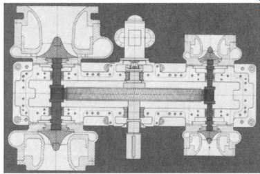
Fig. -10 shows the longitudinal section of a planetary gear with rotating planet carder. The sun pinion and the planet carder with the three planets rotate in the bearings. The outer ring with internal teeth (annulus) is fixed firmly to the casing.
The permissible speed of the slow-running shaft is limited principally by the centrifugal force of the planets and the resulting beating pressure on the bearing pins. The sense of rotation of input and output shafts is the same.
Planetary gears with rotating annuli are shown in Fig. -11. Here, the stationary planet carder with the three planets is fixed to the gear casing, and the internal tooth annulus connected with the low-speed shaft rotates. Input and output shafts rotate in opposite directions.
It should be noted that Fig. -10 and 11 show the gearing with helical teeth, whereas Fig. -9 illustrates spur gears incorporated in the epicyclic package.
The reason for frequently using helical gears is perhaps best explained by reviewing their precursor, stepped gears.
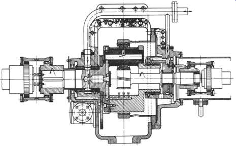
Above: Fig. -10 Longitudinal section of planetary gear with rotating planet
carrier. (Maag Gear Company, Zurich, Switzerland.)
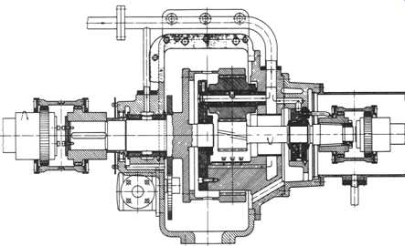
Above: Fig. -11 Planetary speed-reducing gear with rotating planet carrier.
(Maag Gear Company, Zurich, Switzerland.)
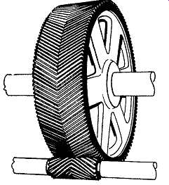
Since only a few teeth of a pair of spur gears are in contact at the same time, meshing of these gears may be accompanied by a slight impact as the load shifts from tooth to tooth. This is because the teeth undergo slight deformation as the load moves over the tooth surface. At low speeds, this is not a serious factor, but as speeds become higher and higher, this deformation makes it more difficult to mesh spur gear teeth without noise and shock. Although accurate machining of spur gear teeth is a major factor in smoothing out any slight irregularities of transmitted motion and torque, these irregularities are minimized only when the gears are designed to distribute the load on several engaging teeth. An early method of accomplishing this result was by the use of stepped gears. In this construction, an assembly of two or more narrow gears are mounted on the shaft in such a way that the teeth are staggered ( Fig. -12). Sudden transfer of load from one tooth to another is minimized as each adjacent stagger tooth absorbs part of the load before the preceding tooth leaves the mesh. This increases the number of teeth in contact at any one time. In rare cases, stepped gears are used to permit operation with zero backlash. When used for this purpose, one of the gears is an ordinary spur gear. The meshing gear consists of two narrow gears bolted together in such a position that all play between the meshing gear teeth is eliminated. In general, the stepped type of gear is seldom used for ordinary transmission of power because of the difficulty of equalizing the load among the various tooth faces. For this use, however, the modem development of the stepped gear- the helical gear- is widely employed.
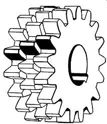
Above: Fig. -12 Stepped gearing predates helical gears. (Prager, Inc., New
Orleans, LA.)
Helical Gears, Parallel Shafts
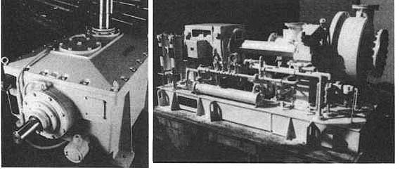
If, instead of two or three narrow gears, a stepped gear were composed of innumerable staggered laminations- each lamination so thin that it no longer appeared as an individual unit - the result would be a gear with smoothly twisted teeth. In actual practice, twisted-tooth gears are machined from solid gear blanks with the twist in the same direction. Such a uniform twist is a true helix, and the resulting gears are called helical gears ( Fig. -13). The angle of twist (helix angle) may range from about 20 degrees to 45 degrees. The helix angle is selected so that several teeth will be in mesh at the same time. Even if only two of these helical teeth are in mesh, a very smooth transfer of power results. As the helix angle is increased, the number of teeth in simultaneous contact and the smoothness of tooth engagement are correspondingly increased. Single helical gears are used in speed reducers as well as speed increasers. The speed reducer shown in Fig. -14 connects a steam turbine to a reciprocating compressor. It accomplishes the speed reduction in two steps, hence the designation double reduction gear.
Another single helical gear is shown in Fig. -15. Used as a speed increaser between a gas turbine operating at 4860 RPM and a compressor operating at 12507 RPM, this speed increaser transmits 23,800 horsepower and has a pitch-line velocity of 540 feet per second (fps).
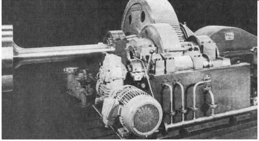
Above: Fig. -14 Double reduction, single helical gear speed reducer for reciprocating
compressor drive. (Maag Gear Company, Zurich Switzerland.)
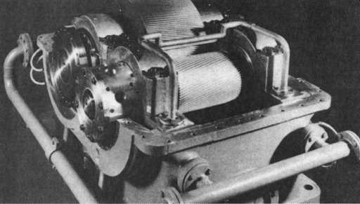
Above: Fig. -15 Single reduction, single helical gear increaser for centrifugal
compressor drive. (Maag Gear Company, Zurich, Switzerland.)
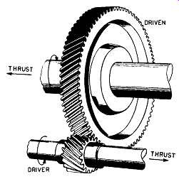
Due to the angularity of their teeth, the operation of helical gears produces axial thrusts that must be absorbed by thrust bearings. In most cases, properly selected rolling element bearings will take care of this thrust. However, by using two pairs of opposed helical gears ( Fig. -16), the thrust of one set of gears balances that of the other. This practice was developed before adequate thrust bearings were available.
Later developments in the economical cutting of gear teeth made it possible to machine two opposed helical gears on a single gear blank. Such a gear is commonly known as a double-helical or herringbone gear ( Fig. -17). High-speed herringbone gears often have a continuous groove machined between the sets of teeth to assist the escape of oil as the gears pass through mesh. Alternatively, the two sets of teeth may be staggered for the same purpose. Either double- or single-helical gear units are widely used in demanding applications where reliability and low maintenance are a must. For example, in the hydrocarbon processing industry, they are specified for process compressors, pump pipeline compressors, fan drives, generator drives, and blower drives. Fig. -18 illustrates a typically demanding application.
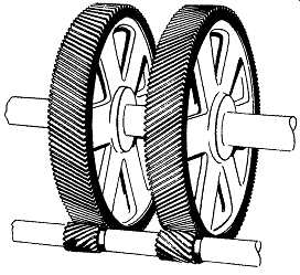
Above: Fig. -16 Two single helical gears mounted mirror-style to equalize
axial thrust generation. (Prager, Inc., New Orleans, LA.)
Above: Fig. -17 Double-helical or herringbone gear (Prager, Inc., New Orleans,
LA.)
Above: Fig. -18 Single helical speed increaser set driving high-speed
compressor wheels. (Bayerische Huettenwerke Sonthofen, Germany.)
The centrally located input gear drives two pinions that are fitted with compressor impellers at each end.
Helical Gears, Nonparallel Shafts
When shafts are not parallel but cross one another, the provision of slanted helical teeth will allow a limited amount of power to be transmitted irrespective of the angle between the shafts. The gears are true helical gears ( Fig. -19) but are sometimes called spiral gears.
Above: Fig. -19 Spiral gearing used in certain right-angle drives. (Prager,
Inc., New Orleans, LA.)
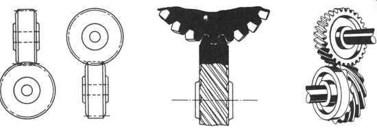
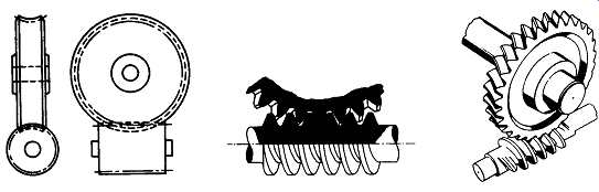
Above: Fig. -20 Nonthroated worm gear set. The teeth are straight
and don’t envelop the worm. (Prager, Inc., New Orleans.)
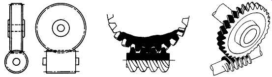
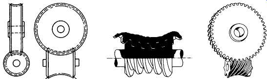
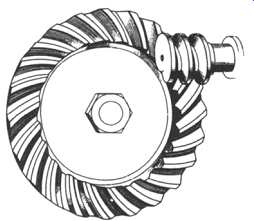
Above: Fig. -21 Single-throated worm and gear. This is the type of gear used most commonly in industrial worm gear sets. The teeth of the gear
are throated (curved) to partially envelop the worm. (Prager, Inc., New Orleans.)
Worm Gears
Where the driving gear of a helical right angle drive is much smaller in diameter than the driven gear, the combination could be called a nonthroated worm gear set ( Fig. -20), the smaller gear being the worm. Worm length, as compared with diameter, permits the helical teeth to encircle the shaft more than once, thus giving the teeth the appearance of threads and giving the worm the appearance of a screw.
When the worm has only one thread (tooth), it’s commonly called a single-thread worm. If there is more than one thread, it’s known as a double-thread, triple-thread, etc., worm. The relative number of teeth on the worm and wheel determines the ratio of speed reduction.
When the teeth of both worm and worm gear are of true helical form, the contacts concentrate on a series of points. This limits the power that can be transmitted by such gears. Although the gears transmit motion very smoothly, excessive wear occurs if much power is involved. For this reason, nonthroated worm gears and helical gears on crossed shafts are not very extensively used.
Since commercial worm gear sets must transmit considerable power, it’s usual to machine the worm gear so that a considerably increased area of tooth surface will make contact ( Fig. -21). This is done by changing the shape of the teeth of the driven gear so that these teeth partly encircle the worm. Such a type is called a throated, or single-enveloping, worm gear and is the type most commonly used in worm gear sets.
Another type of worm gear is the double-throated, or double-enveloping, gear set, employing a throated worm and a throated gar ( Fig. -22). Not only does the gear partly envelop the worm, but the worm also partly envelops the gear, thus further increasing the area of the contacting surfaces. When properly designed and manufactured, these gears are able to carry very heavy loads, although not generally at high speeds.
Above: Fig. -22 Double-throated worm and gear. Both the worm and gear are
throated. As a result, they partially envelop each other. The increased contact
area permits heavy loads to be carried. (Prager, Inc., New Orleans, LA.)
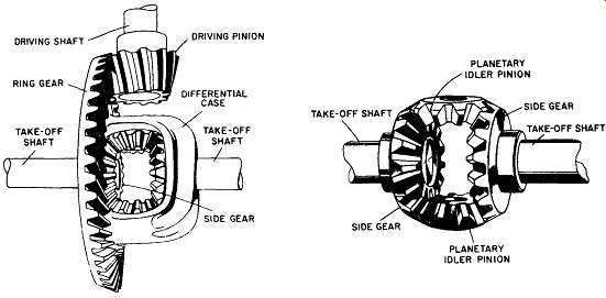
Above: Fig. -23 Differential gear set. Turning of the idler pinions causes
an increase in the speed of the less heavily loaded shaft.
DRIVING SHAFT RING GEAR DRIVING PINION; IFFERENTIAL CASE SHAFT; SHAFT TAKE-I PLANETARY SIDE GEAR PLANETARY IDLER PINION
Bevel Gears
When shafts intersect, the teeth of meshing gears may be cut straight across the faces of conical gear blanks. Such gears are called bevel gears ( Fig. -3). Bevel gears are widely used where a fight angle change in direction of shafting is required, although occasionally the shafts may intersect at acute or obtuse angles. When of equal size and mounted on shafts at fight angles, they are sometimes referred to as miter gears.
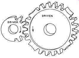
Usually, however, the driving gear is smaller than the driven gear, because in the majority of cases gear sets are employed to obtain a reduction of operating speed.
Bevel gears may be assembled in a special grouping known as a differential gear set ( Fig. -23) such as is used in automotive vehicles. This arrangement of gears is intended to divide power between two variable speed shafts, e.g., to permit the wheels of motor vehicles to rotate at different speeds when the vehicle is turning comers. Observing the left side of Fig. -23, we note a large ring gear that is rigidly attached to the differential gear case. The planetary idler pinions, meshing with the side gears (fight view) are pivoted on and revolve with the case, thereby turning the takeoff shafts. When the load is equal on the takeoff shafts, the entire unit revolves as a solid block. Unbalanced load, however, causes the more heavily loaded shaft and its side gear to slow down. Since the ring gear and case are driven at a constant speed, the planetary idler pinions are forced to turn on their pins as they revolve around the slower side gear. This turning of the idler pinions causes an increase in the speed of the less heavily loaded shaft.
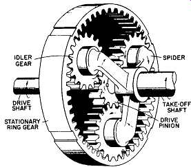
Bevel gears may also be arranged to form a strong and compact planetary reduction gear set ( Fig. -24) similar in principle to that shown in Fig. -9.
The drive pinion engages several idler (planetary) gears, causing them to rotate.
These gears then roll around the stationary gear, dragging the spider with them and causing the takeoff shaft to rotate. Speed reduction depends on the ratio of the number of teeth on the drive pinion to the number of teeth on the stationary gear.
Spiral Bevel Gears
In the same way that the teeth of a spur gear can be twisted to make a helical gear, the teeth of an ordinary bevel gear can be twisted to form a spiral bevel gear ( Fig. -25). Because the teeth of a bevel gear are developed on the surface of a cone, these twisted teeth will take the form of a spiral; thus the gears are called spiral bevel gears. The angle of the spiral is selected so that one end of each tooth enters mesh before the other end of the preceding tooth has disengaged. As with helical gears, this results in very smooth transfer of power.
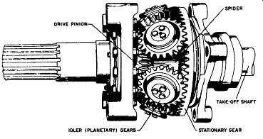
Above: Fig. -24 Bevel gears arranged to form a strong and compact
planetary reduction gear set. DRIVE SPIDER TAKE-OFF SHAFT IDLER (PLANETARY)
GEARS STATIONARY GEAR
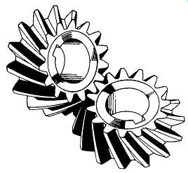
Above: Fig. -25 Spiral bevel gears. LINE CONTACT
Above: Fig. -26 Hypoid gear and pinion. These gears transmit motion between nonintersecting shafts crossing at a right angle. The pitch surfaces are hyperbolic
in form.
Hypoid Gears
Hypoid gears ( Fig. -26) are used where shafts cross, one below the other, and the design of the machine precludes the use of a worm and gear. This may result where space limitations require that one of the shafts be moved aside, where several pinions on a single shaft drive several cross shafts, where a small pinion must transmit high power, or where rigidity requires a supporting beating on each side of each gear.
Where any of these conditions exist, hypoid gears provide a strong, smooth, and quiet drive. The shafts of practically all hypoid gear sets cross at right angles.
Although the ordinary hypoid gear is similar in appearance to a spiral bevel gear, it’s not developed on the same type of pitch surfaces. Two conical pitch surfaces on intersecting shafts roll on each other with line contact and without sideslip, but if the shafts don’t intersect, i.e., if they cross one below the other, the cones don’t make contact along a line and don’t roll without sliding. Instead, they meet at a point and roll with more or less side-slip, depending on the positions of the shafts. Gear teeth developed on such surfaces on crossed shafts would also make point contact and would give poor service.
To increase contact area and improve gear service, it’s necessary to replace the cones with surfaces that will bear on each other along a line of contact. This line contact is obtained by employing curved pitch surfaces of hyperbolic contour.
The teeth developed on these hyperbolic pitch surfaces also meet in line contact, thus distributing the load over considerable tooth surface. Unit loading on the metal is reduced, and the ability to transmit power is increased. The working surfaces of the meshing teeth, however, are always subject to side-slip and consequent friction.
Such gears are called hypoid gears. Although most hypoid gears look like spiral bevel gears, this is not always the case. In rare cases, extreme offset of the shafts and high ratios of reduction will require gears such as shown in Fig. -27. In this case, the pinion has only one tooth, which causes it to resemble a worm.
Special Gear Sets for Process Plant Applications
Process plant gear sets often incorporate one or more of the gear types, configurations, and arrangements that we have discussed here. Fig. -28 through 2-31 show high-power-density parallel shaft double-reduction gears ( Fig. -28), special or customized process machine drives ( Fig. -29), cooling tower fan drives with double-reduction and right-angle output ( Fig. -30), and completely packaged drive systems that include driver, speed change, driven machine, and support systems such as lube oil supplies ( Fig. -31).
Above: Fig. -27 Hypoid gear with extreme offset will require pinion to resemble
a worm.
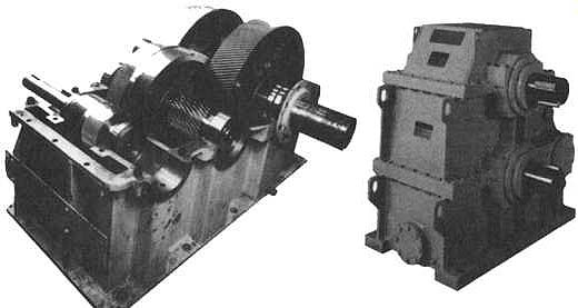
Above: Fig. -28 This double-reduction helical gear set employs the gear geometries
shown earlier in Fig. -16 and 17.( WesTech Gear corporation, Los Angeles, CA.)
Above: Fig. -29 Special process machine drives can be built in almost limitless
variations of geometry and arrangements.
Above: Fig. 30 Right-angle drives such as this large cooling tower fan gear
often use a combination of gear types to accomplish both speed change and changes
in drive direction. (WesTech Gear Corporation, Los Angeles, CA.)
Above: Fig. 31 Complete process systems often include speed-up gears for
motor-driven blowers and high-speed pumps. This entire unit is being applied
in a solvents recovery process. (WesTech Gear Corporation, Los Angeles, CA.)
Prev.: Electric Motors and Controls | Next: Gas Turbines
Home top
of page