AMAZON multi-meters discounts AMAZON oscilloscope discounts
OVERVIEW OF GAS COMPRESSION MACHINERY
The purpose of compression is simply to increase the pressure of a gas from one level to another. Depending on a host of circumstances and situations, the pressure increase imparted to a gas will be from a fraction of a pound per square inch (psi) (or a few pascals) in laboratory equipment to literally tens of thousands of psi in hyper-compressors used for the manufacture of polyethylene.
Before we embark on our more thorough consideration of centrifugal compressors, we should examine gas compression machinery in general. In a typical process plant, compression services include instrument and plant air, combustion air for burners and furnaces, gas circulation, or simple elevation to pressure conditions that will allow chemical reactions to take place. Gas volumes will vary from laboratory quantities to flows well in excess of a million cubic feet per minute (~2 million m^3/hr). Two principal methods are used to compress gases. The first method is to trap a volume of gas and displace it by the positive action of a piston or rotating member; we call these machines positive-displacement compressors. The second method uses dynamic compression; it’s accomplished either by the mechanical action of contoured blades, which impart velocity and hence pressure to the flowing gas, or by the entrainment of gases in a high velocity jet of the same or another gas (e.g., steam). The entrainment principle is generally found in ejectors that operate with inlet pressures below atmospheric pressure, but since our definition of process machinery implies the existence of moving parts, we have elected not to cover ejector devices in this text.


above: Atlas Copco model ZH. Oil-free centrifugal compressors, 400-2750 kW, 500-3500 hp.
The two major groupings of compression machinery, positive displacement and dynamic, can be further subdivided as shown in FIG. 1. Positive-displacement units are those in which successive volumes of gas are confined within a closed space and elevated to a higher pressure. Reciprocating compressors are positive-displacement machines in which the compressing and displacing element is a piston that moves back and forth within a cylinder. Rotary positive-displacement compressors are machines in which compression and displacement is effected by the close meshing of rotating elements. Sliding-vane compressors are rotary positive-displacement machines in which axial vanes slide radially in a rotor. This rotor is eccentrically mounted in a cylindrical casing. Gas trapped between the vanes is compressed and displaced. Liquid-piston compressors are rotary positive-displacement machines in which water or other liquid is used as the piston to compress and displace the gas handled. Roots| straight-lobe compressors are rotary positive-displacement machines in which two mating lobed impellers trap gas and displace it from intake to discharge. There is no internal compression. Helical- or spiral-lobe compressors are rotary positive-displacement machines in which two intermeshing rotors, each with a helical form, compress and displace the gas.
Dynamic compressors are continuous-flow machines in which either the rapidly rotating element or ejector nozzle accelerates the gas as it passes through the element. The velocity head is converted into pressure, partially in the rotating element and partially in stationary diffusers or blades. Centrifugal compressors are dynamic machines in which one or more rotating impellers, usually shrouded on the sides, accelerate the gas. Main gas flow is radial. Axial compressors are dynamic machines in which gas acceleration is obtained by the action of the bladed rotor shrouded on the blade ends. Main gas flow is axial. Mixed-flow compressors are dynamic machines with an impeller form combining some characteristics of both the centrifugal and axial types.
Here we will treat centrifugal compressors. Other types of compressors are covered in succeeding sections.
======
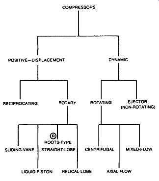
FIG. 1 Major compressor types: COMPRESSORS POSITIVE--DISPLACEMENT DYNAMIC
RECIPROCATING SLIDING-VANE ROTARY ROTATING EJECTOR (NON-ROTATING) ROOTS-TYPE
STRAIGHT-LOBE CENTRIFUGAL MIXED-FLOW LIQUID-PISTON HELICAL-LOBE AXIAL-FLOW
======
CENTRIFUGAL COMPRESSORS
Centrifugal compressors are employed in numerous fields" chemical and petrochemical industries, refineries and fertilizer plants, nuclear reactors and air separation plants, iron and steelworks, production of liquefied natural gas (LNG) and substitute natural gas (SNG), cryogenic and refrigeration plants, mining, transportation and storage of gas, onshore and offshore installations. The range of applications can be expanded still further by combining these centrifugal compressors with other compressor types such as axial-flow or reciprocating compressors.
The wide range of processes in which centrifugal compressors are employed makes varying demands on these machines. Compressor design is dependent on such factors as the fluid handled, the pressure ratio, the volume flow, the number of interstage coolers, injection and extraction of the medium, and the type of shaft sealing.
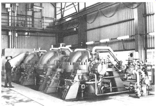
FIG. 2 Horizontally split compressors in a modem process plant. (Mannesmann
Demag, Duisburg, Germany.)
Taking all these factors into consideration, the major compressor manufacturers have developed series of centrifugal compressors offering an optimum engineering solution implemented by the use of standard components. These series include the two basic types, distinguished by horizontally or vertically split casing (see FIGs 2 and 3), compressors with two or three pairs of main nozzles, and compressors with additional sidestream nozzles. A few of the many possible nozzle arrangements are depicted in FIG. 4.
Horizontally split casings with nozzles in the lower half permit simple removal of the rotor and facilitate the checking of labyrinth clearances and O-rings. As pressure levels rise and gas molecules become smaller, vertically split casings are employed.
Horizontally Split Centrifugals
Centrifugal compressors with horizontally split casings typically permit internal pressures of 70 bar with small volume flow rates and volume flow rates of up to 300,000 ma/hr at low pressures. Drive ratings of 30 MW for single-casing machines have already been implemented.
FIG. 5 shows a cross section of a six-stage horizontally split centrifugal compressor. Standardized components ensure high availability and easy fitting. The two halves of the casing are sealed and bolted together.
The rigid structure is supported at the centerline, thus preventing vertical shifting of the compressor shaft as a result of thermal expansion. For erection and dismantling purposes, the top half of the casing, complete with the associated stationary components, can be handled as a single unit. All types of drivers can be employed, for example, gas turbines, steam turbines, and electric motors.
Many processes require compression of a fluid in one process stage only, i.e., continuous compression from the first to the final stage with constant mass flow rate. Most major centrifugal compressor manufacturers build machines for this field of application with up to nine or as many as twelve compression stages. Aerodynamic matching of the individual compression stages is by means of diaphragms with diffuser channels and vaned return passages. Following the final stage, the compressed gas enters a collecting chamber in the form of a volute before it reaches the discharge nozzle. The shaft is supported in bearings outside the compression space. Shaft sealing is by means of tried and proven systems such as labyrinth, floating ring, mechanical contact or non-contact seals.
The wide range of possible variations in the materials used and in the selection of the sealing system render compressors of this series suitable for virtually all fields of application in industry, chemical and petrochemical processes, and for almost all gases and mixtures of gases.
FIG. 3 Vertically split (barrel-type) centrifugal compressor. (Mannesmann
Demag, Duisburg, Germany.)
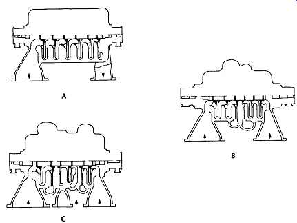
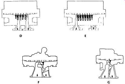
FIG. 4 Nozzle arrangements and impeller lineups typically available in centrifugal
compressors. (A) Straight-through, (B) back-to-back, (C) back-to-back with
sidestream entry, (D) straight-through (barrel-type), (E) back-to-back (barrel-type),
(F) future addition to stage possible, (G) single stage. (Mannesmann Demag,
Duisburg, Germany.)
Sidestream Compressors
In multistage refrigeration processes, different mass flows pass through the various refrigeration stages. Sidestreams therefore have to be injected into or extracted from the main flow in the compressor at process-dependent intermediate pressures and temperatures. Injection or extraction is by means of additional nozzles. (The flow path through a sidestream compressor is illustrated in FIG. 6.) In the case of gas injection, the sidestream is mixed with the main stream in the return channel. Mixing takes place over the entire periphery. When a sidestream is extracted, a separating volute removes part of the main stream. The compressor stages are designed to correspond to the stages of the refrigeration process. The working media for refrigeration processes are primarily ethylene, propylene, ethane, and propane. Refrigeration processes usually form a closed cycle, rather less frequently a semi-open cycle.
In centrifugal compressors with two main nozzle pairs, the two process stages can be arranged back to back, i.e., flow in the two process stages is in opposite directions, or they can be arranged in series. In the double-flow version, the compression process of both stages terminates in a common discharge nozzle.
Back-to-back arrangement of the first and third stages or series arrangement of the stages is also possible. Typical back-to-back arrangements are shown in FIG. 7.
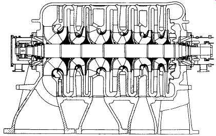
FIG. 5 Horizontally split compressor with two sidestream entry nozzles.
(Mannesmann Demag, Duisburg, Germany.)
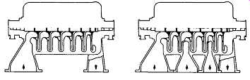
FIG. 6 Flow path through horizontally split straight-through compressor
(left) and sidestream compressor (right). (Mannesmann Demag, Duisburg, Germany.)
Tried and proven labyrinth seals separate the individual process stages. The choice of shaft seal system is dictated by the service. Whereas casings with two main nozzle pairs are widely employed for a variety of media and processes, casings with three process stages are mainly employed for air, oxygen, and nitrogen. The medium is normally cooled outside the compressor.
Interstage cooling produces an almost isothermal compression process. This requires the least compression work. Intercooling also becomes necessary when the temperatures produced by compression have to be limited.
In most compression systems, the coolers are mounted separately, permitting a high degree of freedom in design and layout. However, compressors with internally arranged coolers are available from some manufacturers and may merit consideration when the ultimate in compactness must be achieved.
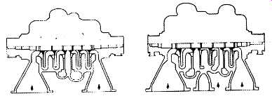
FIG. 7 Compressors with back-to-back oriented impellers. (Mannesmann Demag,
Duisburg, Germany.)
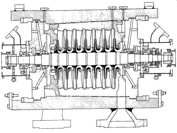
FIG. 8 Cross section of vertically split (barrel-type) compressor. (Mannesmann
Demag, Duisburg, Germany.)
Vertically Split Compressors
Vertically split (barrel-type)centrifugal compressors are the preferred, and sometimes mandatory, design for high pressures or for compressing gases rich in hydrogen. The cylindrical casing ensures good stress distribution and extremely good gas-tightness. Unlike the casing, the stationary internal components of the compressor, with the exception of seal components, are horizontally split. During assembly of the compressor they are mounted together with the rotor and inserted axially into the casing. The end covers are retained by shear ring segments. A cross-section view is shown in FIG. 8.
The inlet and discharge nozzles are welded to the cylindrical casing or, where heavy wall thicknesses are involved, are integral with the casing; the pipework is bolted to these nozzles. These compressors are also built for two process stages; in this case they feature two main nozzle pairs.
The main fields of application for barrel-type compressors are in handling gases rich in hydrogen; hydrogenation cracking; synthesis of ammonia, urea, and methanol; gas lift and reinjection; and transportation of gas in pipelines.
A compressor with one stage is often adequate for compression applications involving a low head. For such applications, the user may choose from compressor types that may be vertically or horizontally split. As mentioned earlier, the vertically split version is particularly suitable for high pressures and for compressing gases of low molecular weight.
Depending on the operating conditions involved, the tried and proven systems employing labyrinth, mechanical contact, or floating ring seals are used for shaft sealing. Other seal systems may go under the names of trapped bushing seal, gas phase mechanical seal, cone seal, etc., but each type represents merely a variation of the three principal configurations.
Fields of application for single-stage process compressors include phthalic acid anhydride plants and cupolas, oxosynthesis, and water treatment. In addition, they are suitable for handling all gases and gas mixtures in the main and auxiliary processes in the chemical and petrochemical industries. They also find application in the transportation of natural gas and mineral oil gas as well as in closed-loop systems in nuclear technology.
Compressor Trains
Large pressure ratios cannot be handled by one casing alone. Similarly, it’s not possible to split the compression cycle into more than two or three process stages within one casing. The major compressor manufacturers therefore build compressor trains that may consist of up to four separate casings. A train with three separate casings is shown in FIG. . These separate compressors, which need not be of the same type, are interconnected by couplings; they can be powered by a common driver. When additional transmission gearing is used, the compressor casings may also be run at different speeds. The train is designed so that a minimum of dismantling is necessary for maintenance, i.e., when a vertically split casing is used, it’s located at the opposite end to the driver.
The compressor train can be arranged on a common baseframe. In special applications, for instance, offshore installations, this baseframe can be of torsionally stiff design.
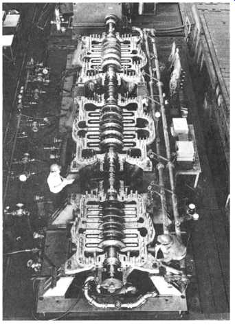 FIG. 9 Centrifugal compressor train. (Mannesmann Demag, Duisburg, Germany.)
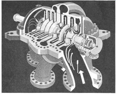
FIG. 10 Cutaway view ofhorizontally split centrifugal compressor. (Mannesmann
Demag, Duisburg, Germany.)
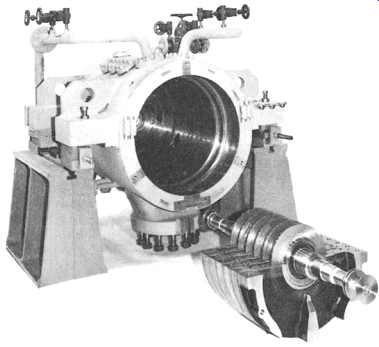
FIG. 11 Barrel-type compressor casing and internals. (Mannesmann Demag,
Duisburg, Germany.)
Construction and Mode of Operation
Each application requires its own casing configuration. In spite of this, the intemal design and construction of a given manufacturer's centrifugal compressor is often essentially the same. This allows the use of standard components.
The components that are important for the compression function are the rotor and the energy-converting parts, as illustrated in FIGs 10 and 11.
The rotor consists of the shaft and the impellers. The number of impellers is determined by the thermodynamic operating conditions, but it’s limited by the mechanical and dynamic behavior of the rotor. The shaft is carried in pressure-lubricated tilting-pad bearings; one of these is purely a radial bearing, while the other is either a separate or a combined radial and thrust bearing. The shaft is generally provided with a balance piston to reduce axial thrust.
Shaft seals separate the gas spaces from the oil-lubricated bearings and the atmosphere. Simple labyrinth seals, multiported labyrinths with buffer gas, mechanical contact, or floating ring seals are employed, the choice being dictated by the process involved and the fluid handled.
The materials for the rotor, internals, and casing are selected on the basis of their mechanical properties and compatibility with the fluid to be compressed.
A lube oil system and a seal liquid system supply the bearings and the liquid seals with the required volumes of oil and seal liquid.
The fluid to be compressed passes through the inlet nozzle and aerodynamically designed inlet channel into the first impeller. The first impeller may be preceded by an adjustable inlet guide vane unit. Impellers and the diffusers following them are designed so as to provide an optimum low-loss compression cycle. After the diffuser channel, the gas enters the return bend, which guides it to the vaned return channel, and it then reaches the impeller of the next stage with the correct angle of incidence.
Immediately following the final stage or an intermediate stage, after which the compressed gas leaves the compressor, the diffuser opens out into a volute that widens gradually in the direction of flow to match the increase in volume.
Impellers
The head to be produced and the volume flow to be handled provide the design criteria for impellers. The total energy y that can be transferred by the impeller is a function of the peripheral velocity u2 and the pressure coefficient psi:
An upper limit is set to the permissible peripheral velocity by the type of impeller and the mechanical properties of the materials from which it’s made. The pressure coefficient increases with increasing blade outlet angle ~2. However, the impeller geometry is not exclusively determined by the maximum energy that can be transferred.
Further criteria include good overall efficiency of the stage and a broad envelope of curves with as steep a rise as possible toward the surge limit, thus ensuring good partial load controllability and stable operation within the plant (immunity to pressure fluctuations).
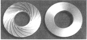
FIG. 12 Impeller with backward-leaning blades, shown before cover assembly
(Mannesmann Demag, Duisburg, Germany.)
The standard impeller in many centrifugal compressors is the type with backward-leaning blades and cover ( Figure 12). It represents a good compromise to meet the aforementioned requirements. This type of impeller may feature blades curved in two or three dimensions. Impellers with three-dimensional blading ( Figure 13) have high capacity limits, due to the large eye diameter relative to the outside diameter and a large outlet width. Three-dimensional impellers are among the standard features available for modem centrifugal compressors.
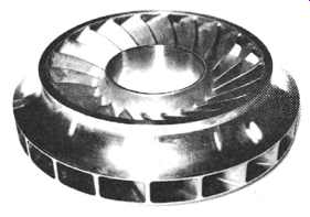
FIG. 13 Impeller with three-dimensional blades. (Mannesmann Demag, Duisburg,
Germany.)
Manufacture of Impellers. Five principal manufacturing methods are typically available for the efficient production of impellers: milling and riveting, milling and brazing, milling and welding, welding and welding, and casting.
Impellers fabricated by milling and riveting have the gas passages milled from the solid impeller disc. The cover is riveted in place. This long-established method combines great mechanical strength and reliability with high aerodynamic quality, i.e., dimensional accuracy (particularly important for narrow gas passages) and good surface finish. More recent mechanical analyses have especially demonstrated the system-damping properties of the riveted fixing, properties that afford enhanced protection against fracture due to alternating stress cycles.
Milled and brazed impellers are used when thin blades and narrow gas passages with good aerodynamic properties are necessary. As in the case of riveted impellers, the gas passages are milled from the solid impeller disc; the cover is then brazed into place with a gold-nickel brazing alloy, using a high-temperature, high-vacuum process. The strength of the brazed joint is equal to that of the parent metal. It’s totally immune to HES stress corrosion cracking.
When access to the gas passages is good, i.e., when the passages are wide, the impellers are of milled and welded or welded and welded construction. The blades are either milled from the solid impeller disc or welded to it. In both instances, the cover is welded to the blades by a continuous weld.
If a number of identical impellers are required, casting is the most economical method of manufacturing them. Large impellers are cast in sand molds. Precision casting processes that ensure unusually good quality of the product are being used to an increasing extent for small impellers.
Impeller Testing. Tests are carried out on material specimens prior to and after manufacture to prove the required properties. On completion of manufacture, the dimensions of the impeller are checked, after which the impeller is then tested for cracks, using dye penetration or magnetic particle methods. The impeller is then initially balanced and run at overspeed. This speed may be so high that flow and cold strain hardening may take place at the stress peaks. After overspeeding, the impeller is once again checked for dimensional accuracy and tested for cracks. On successful completion of these tests, the impeller is rebalanced.
Rotor
The shaft carries the impellers and the balance piston, as illustrated .
It’s supported in tilting-pad, plain, or modified (contoured) sleeve beatings. The impellers and balance piston are shrunk onto the shaft. Multipart rings or similar components locate the impellers in the direction of the axial thrust. The shrink fit offers the advantage of uniform stress distribution over the whole circumference and a constant self-centering effect. This shrink fit is designed so that after the bore has expanded due to centrifugal force at maximum speed, sufficient shrinkage effect still exists to transmit the torque and the axial thrust. At the same time, the impellers can be removed whenever necessary without damage.
The balance piston balances part of the axial thrust produced by pressure differentials across the impellers. Part of the axial thrust is automatically balanced with a back-to-back layout. All component parts such as shaft, impellers, balance piston, and couplings are separately balanced, after which the complete rotor is assembled.
Each time another component is added, concentricity of running is checked. The stresses produced in the shaft by the shrink-fit method of mounting the impellers and balance piston are relieved by running the complete rotor up to operating speed.
Rotor Dynamics. Detailed vibration analyses as early as the preliminary design stage ensure the operational availability of modem, well-engineered centrifugal compressors. These analyses investigate the following vibration phenomena: resonance behavior, stability, and torsional analysis.
Investigation of the resonance behavior includes computation of the first and second lateral critical natural frequencies based on the bearing stiffness and damping for each casing. Precise determination of the critical natural frequencies, which are principally lateral vibrations of the rotor caused by unbalance forces, allows multistage compressors to be operated at a speed between the first and second lateral critical speeds.
The stability behavior describes the behavior of the rotor when the vibrations are self-excited. This essentially includes vibrations excited by the specific spring and damping characteristic of the bearings (oil whip) and rotor-dynamic effects of labyrinths and sealing elements.
The torsional analysis covers torsional vibrations produced by electric motors when switching occurs in the supply network and when a synchronous motor is run up to operating speed asynchronously.
A precise knowledge of these interrelated factors ensures trouble-free operation and a high degree of operational availability of major, unspared centrifugal compressors.
Bearings
Tilting-pad bearings support and locate the compressor rotor. They employ the hydrodynamic principle and are designed in the light of the most recent scientific and engineering knowledge in this field. The running surfaces of the bearings are divided into segments and inserted into the horizontally split bearing bracket. This bearing bracket is positioned in the bottom half of the bearing housing and is typically secured in place by a bolted bearing retainer. Properly designed compressor bearings can be inspected without the compressor casing having to be opened.
All bearings have pressure-oil lubrication. A lubricating oil system supplies them with a flow of oil sufficient to form an oil film on the running surfaces and to dissipate the heat produced by friction. Oil is piped centrally to the bearings.
Retaining rings fitted at both sides control the rate of discharge of oil from the bearing via the gap set.
Radial Bearing. The radial bearing-often specially developed by capable compressor manufacturers - is a multipad bearing with four or five pads arranged so that the stationary shaft rests on one of them or, in some designs, between pads. In a multipad bearing, the reaction forces act over the entire circumference and therefore stabilize the position of the shaft. In addition, the tilting pads adjust automatically to suit the operating conditions; optimum load distribution is therefore achieved at all times. With the exception of certain special designs, these pads are symmetrically supported and therefore are unaffected by the sense of rotation. FIG. 15 depicts a radial tilting-pad beating.
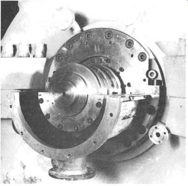
FIG. 14 Compressor bearing housing with combination thrust and radial bearings.
(Mannesmann Demag, Duisburg, Germany.)
FIG. 15 Tilt-pad radial bearing. (Mannesmann Demag, Duisburg, Germany.)
Thrust Bearing. At the non-drive end of the compressor, the radial bearing is combined with a thrust bearing--also frequently specially developed by the compressor manufacturer. This bearing employs the principle of a double adjustable pad-thrust bearing and absorbs the residual rotor thrust resulting from the unbalanced gas forces acting on the impellers and balance piston.
The tilting pads are sometimes asymmetrically supported. The axial thrust is determined with the most modem methods available, taking into consideration all the aerodynamic effects that arise. A certain amount of residual thrust has a stabilizing effect, since the rotor is then in contact with a specific side of the beating. The design chosen and the load-bearing capacity of the thrust beating must ensure the operational readiness of the compressor even if thrust reversals and sudden loads occur during the widely varying operational phases the compressor may experience.
FIG. 16 illustrates a combination radial/thrust tilting-pad bearing.

FIG. 16 Combined radial and thrust tilt-pad bearing for centrifugal compressor.
(Mannesmann Demag, Duisburg, Germany.)
Sealing Elements
The long-term, reliable operation of centrifugal compressors must be ensured by thoroughly well-proven sealing elements.
Labyrinth seals ( FIG. 17) minimize the flow around the impellers and hence also minimize leakage losses. These labyrinths are located over the rim of the impeller eye on the inlet side and close to the shaft over the hub at the back of the impeller on the discharge side. Centrifugal compressors with several nozzle pairs employ labyrinth seals to separate the individual process stages. Labyrinth seals that prevent lube oil and oil mist from escaping from the bearing chambers are also used to seal the bearing housings. Thoroughly proven sealing systems seal the shaft exists. Depending on specific requirements, multiported labyrinth, floating ring, or mechanical contact systems are employed for this purpose.
Multiported labyrinth seals ( FIG. 18) with buffer gas injection are used when buffer gas can be allowed to mix with the process gas or when leakage of process gas is permissible. Provision for ejection can be made in order to avoid excessive leakage of process gas. In all other instances, floating ring or mechanical non-contact or contact seals are used, the former being employed for use with high pressures, the latter being used with clean gases.
Labyrinth Seal
The labyrinth seal is a noncontacting seal. It consists of a number of sealing strips in an insert in the stationary part of the compressor. This insert is horizontally split and easily replaced. Sealing strips are also sometimes fitted to the shaft. "Straight" or stepped labyrinths may be employed, depending on the specific need.
FIG. 17 Labyrinth seals surround each impeller of this centrifugal compressor
rotor. (Mannesmann Demag, Duisburg, Germany.)
FIG. 18 Multiported oxygen compressor labyrinth seal. (Mannesmann Demag,
Duisburg, Germany.)
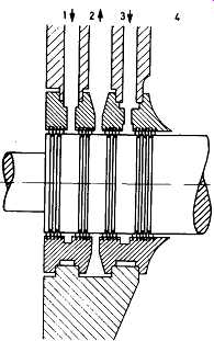
FIG. 19 Multiport labyrinth seal, cross-section view. (Mannesmann Demag,
Duisburg, Germany.)
The labyrinth seal forms a series of throttling points, at each of which the pressure differential is decreased. The smaller the clearance - the distance between the labyrinth strip and the surface of the shaft--the more the leakage is reduced.
The turbulence zones between the strips enhance the throttling effect. The pressure difference involved dictates the number of labyrinth strips. If absolutely reliable separation of the oil and process gas spaces is necessary, a multiported labyrinth seal ( FIG. 19) with injection of buffer gas under controlled pressure is used.
Part of this gas flows outward and prevents atmospheric air from entering, while the remainder passes into port 2 at lower pressure. This space is connected to a leak-off line.
Ports 3 on the suction and discharge sides of the compressor are interconnected and can be controlled and monitored jointly. The pressure is adjusted so that, although it’s lower than the pressure of the buffer gas in port l, it’s higher than the pressure in port 2, causing some gas to flow into that port and mix with the buffer gas there. This arrangement ensures that, in the event of a fault in the discharge line, neutral buffer gas may enter the compressor via port 2, although the gas being compressed inside the centrifugal compressor cannot escape to the atmosphere. Ingress of buffer gas into the compression spaces is normally prevented by the pressure drop across port 2.
The multiported labyrinth system is very adaptable. For instance, a seal employing buffer gas only and without port 2, with a smaller flow of buffer gas into the compressor, is just as feasible as a seal without buffer gas from which a mixture of atmospheric air and the compressed medium are evacuated via port 2.
Floating Ring Seal. In conjunction with a seal liquid introduced under pressure, the floating ring seal illustrated in FIG. 20 prevents process gas from escaping at even the highest of operating pressures. It operates without mechanical contact and therefore without wear. This type of seal consists of the inner ring between the process gas space and the seal liquid space, and the outer ring that permits enough seal liquid to escape outward to ensure adequate cooling of the seal. The form of the intermediate ring leads to intensive heat dissipation away from the inner ring. Sealing is maintained by the controlled seal liquid pressure being above the process gas pressure at all times. Clearance between the inner ring and the shaft is such that only very little seal liquid passes through to the gas side. Since this clearance is smaller than the bearing clearance and also because of rotor dynamics considerations, the sealing rings are designed to float, i.e., they can follow any radial shaft deflections without acting like bearing supports.
The seal liquid enters the seal via supply pipe 1. Most of it’s discharged outward through the radial gap formed by the outer ring. A small volume flows into port 5 via the radial gap formed by the inner ring. Seal liquid is prevented from entering the compressor by a constant flow of buffer gas from the supply pipe 7 to port 5 via labyrinths. The mixture of seal oil and buffer gas is led via connection 6 to an automatic separator.
Mechanical Contact Seal
The mechanical contact seal shown in Fig. 21 employs a stationary carbon ring in sliding contact with a rotating ring manufactured from high-quality material with a special finish. A seal liquid is employed. This type of seal is also effective when the compressor is at standstill and the oil pumps have been shut down.
The main components are the carbon ring and the rotating ring for inward sealing. In the outboard direction, a floating ring controls the flow of the seal liquid that cools the seal.
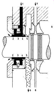
FIG. 20 Cross section of floating ring seal. (Mannesmann Demag, Duisburg,
Germany.)
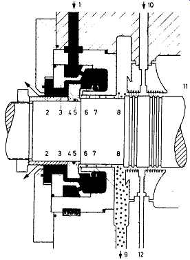
FIG. 21 Mechanical contact seal, cross section view. (Mannesmann Demag,
Duisburg, Germany.)
The seal liquid enters the seal via the supply pipe 1 and flushes the seal ring components via the holes in the distributor ring. The pressure of the liquid is higher than that of the gas, so that the carbon ring, under constant spring pressure, is always kept in sliding contact with the rotating ring. Some of the liquid wets the sliding surface 5 and reduces wear. Only a very small proportion of this liquid passes to the gas side. A controlled flow of buffer gas flowing from the supply pipe 10 through a labyrinth to port 8 entrains this leakage liquid and leads it via outlet 9 to the separator.
O-rings fitted externally and within the seal reliably separate the buffer gas and seal liquid spaces.
Mechanical Non-Contact Seals ("Gas Seals"). These novel seals are very similar in function and geometry to mechanical contact seals. Instead of a sealing liquid, they use a small quantity of a clean sealing gas. The seal faces operate without actually making contact. The escaping seal gas separates the seal faces by a fraction of a thousandth of an inch.
Casings
The two halves of horizontally split compressors are joined together by hydraulically pre-tensioned bolts. The joint is sealed by a suitable sealant, where necessary of the string type. The vertically split casings are provided with end covers retained by shear tings. O-rings or O-ring joints between inner casing and barrel casing provide proper sealing of the gas zone from the atmosphere.
Casings are supported at the centerline. The pedestal supports at the drive end are fixed points, so that axial thermal expansion is in the direction of the free end of the shaft. Lateral alignment is provided by guide lugs in the vertical center plane of the compressor. Thermal expansion of shaft and casing is compensated by the rotor being located by the thrust bearing at the free end of the casing.
Positioning of the suction and discharge nozzles can be arranged to suit requirements. Compressor casings are hydraulically tested at 1.5 times the maximum operating pressure.
Stationary Components
The term "stationary components" refers to the inlet channel, the diffuser, and the return channel.
Impellers achieve optimum efficiency and operating characteristics only if the inlet flow is free of disturbance, i.e., unswirled, and exhibits a uniform velocity profile. Factors such as these are extremely important for impellers of high suction capacity.
Single-shaft process compressors have radial intakes, and the flow therefore has to be deflected through 90 degree prior to entry into the first impeller. High-quality compressors are produced with inlet channel designs that meet the above requirements. These incorporate standard, stationary blades, which, distributed over the periphery, exhibit defined angular settings. Similarly, these centrifugal compressors would have as a standard vaneless annular diffusors that have parallel walls or profiled cross sections. This feature ensures a wide range of regulation with almost constant optimum efficiency.
Leading manufacturers have developed special cross-sectional profiles that produce wider ranges of regulation and better efficiencies than parallel-wall diffusors--especially with high-capacity impellers. As the gas passages become smaller in cross-sectional area, the surface finish of the diffusor has a decisive effect on the stage efficiency. In special cases, the surfaces are therefore coated.
Particular importance is attached to smooth inflow into the following impeller in the design of the return channels, the blading of which is generally profiled. Like the impellers, they are normally milled from the solid material to ensure a superior surface finish and dimensional accuracy.
Auxiliary Equipment
The driver, suitable gearing, and the couplings have to be matched, with the compressor, to the specific application requirements of the plant and to the conditions on the site. It’s only then that the maximum of operational reliability is ensured.
One of the requirements for smooth and economical compressor operation is control and regulation to match operational needs plus inherent functional reliability of the coolers and lubrication and seal liquid systems.
Monitoring of the beatings via the oil temperature, for example, and measurements of shaft vibrations and shaft position ensure that potential trouble during compressor operation is recognized at an early stage. The monitoring equipment, together with the alarm systems and controls, is accommodated in control panels.
Drive Components
Couplings interconnect the various units of a compressor train. Diaphragm or curved-tooth gear couplings are employed as a rule. Couplings of these types allow angular deflection and axial deflection, but they are nevertheless torsionally stiff.
Gear couplings with convex tooth flanks require precision manufacture. The lube oil system supplies them with lubricant. Coupling hubs are located and secured by keys or oil-hydraulic means to the shaft.
Torsionally elastic couplings are employed if shock torque loads occur, for example, when starting up synchronous motors or if there is a brief drop in voltage.
The shock torque load is absorbed by the deformation of elastic components such as rubber buffers. Owing to the lower torque transmission capacity of these components, torsionally elastic couplings are larger.
Spur gears or epicyclic gears are employed between driver and compressor or between two casings in order to drive centrifugal compressors at the optimum speed.
Coolers
Process coolers are employed for a variety of reasons:
++to limit the maximum temperature of the process gas
++to limit the maximum temperature of the components for safety reasons
++to minimize the compressor power consumption by aiming at isothermal compression
Process coolers are employed as intercoolers and aftercoolers. The principal cooling medium used is water, including seawater. There are various criteria for deciding whether the gas is to flow through or around the tubes of the cooler. These are the quality of the gas, the quality of the cooling medium, and the pressure level involved.
If either the process gas or the cooling medium contains contaminants, the aim is to pass these through the tubes and the relatively clean gas or cooling medium around the externally finned tubes. This is because internal cleaning of the tubes is much easier.
When pressures are high, the process gas will be routed through the tubes because of mechanical strength considerations.
The individual tubes form a bundle, the tube ends of which are expanded into the tube end plates, brazed or welded to produce a gas-tight fit. Depending on the design used, the tubes are combined into bundles or single elements. The single-element design is a lightweight, easily portable unit often allowing economical maintenance of spares. Baffle plates determining the flow of the process gas are provided inside the cooler housing.
Air-cooled process gas coolers are used in special applications. The process gas flows through the tubes around which cooling air flows boosted by fans. Air-cooling requires much larger equipment, and a number of elements are therefore arranged in parallel.
Control
Centrifugal compressors always match the process requirements. They form an integral part of the process plant, the operating characteristics of which are a function of volume flow and pressure.
Centrifugal compressors can be controlled so that they maintain constant pressure at the intake or at a preceding process point, or at the discharge nozzle or following that point. When process control is staged, intermediate pressure can also be maintained. Requirements for constant volume flow can also be met. Daily and annual meteorological influences are taken into consideration. In addition, the compressors have to be protected against unstable operating conditions.
If these requirements are to be met, the operating characteristics of the compressor have to be controlled. This can be done either by varying impeller speeds, by varying the angle of incidence of the gas, or by throttling.
Speed Variation. When speed variation is used, all velocity components are equally affected. This requires a speed-controllable driver or suitable intermediate element. The principal advantage of speed regulation is that only as much energy is required as is needed for the process.
Variation of Angle of Incidence. The compressor characteristic for constant speed can be directly influenced by using an inlet guide vane unit to vary the angle of incidence. Apart from providing economical operation under partial load, this also allows an extension of the characteristic above normal. With constant conditions at the impeller outlet, the changed angle of incidence causes the specific work to be influenced by the relative and absolute velocities at the inlet. With a positive guide vane setting, the total energy is reduced because of the lower relative speed at the inlet. A negative setting has the opposite effect. The influence of a negative guide vane setting generally reaches a peak value between 20 degree and 30 degree After this setting is exceeded, the angled guide vanes choke the flow cross section to such a degree that throttling with local separation phenomena occurs, and this causes losses to increase rapidly.
Toward the lower end of the volume flow range, a positive guide vane setting has an advantageous effect, particularly in the region close to the design point.
The direction of the relative velocity is turned to coincide with the design angle of the leading edge of the blade, and the shock loss otherwise occurring due to an unfavorable approach angle is reduced. In the remainder of the partial load range, a throttling effect resulting from constriction of the flow cross section by the angled guide vanes is superimposed on the aerodynamic effect.
One special advantage of guide vane adjustment is that the stable operating range is extended toward smaller volume flow rates, although this applies to the particular stage only. With multistage compressors, the effect is reduced in proportion to the number of uncontrolled stages.
Throttling. With throttling, the compressor characteristic remains unchanged.
When throttling is performed on the suction side, a throttle valve reduces the compressor inlet pressure when the volume flow rate is increased. Downstream of the compressor, a lower discharge pressure is produced, which corresponds to the pressure ratio associated with the point on the compressor characteristic or compressor performance curve. In relation to the useful compression work, throttling requires maximum specific energy.
Throttling on the suction side and variation of inlet guide vane angle are also used to expand the operating range of compressor plants with speed-controlled drivers.
Antisurge Control. In order to protect the machines from excessively high mechanical loading due to unstable operating conditions (surging), which primarily stress the bearings, compressors can be equipped with antisurge control. One such control is depicted in FIG. 22.
If the delivery required is below the minimum delivery volume of the compressor, the surplus is led away as a sidestream, via a valve. Depending on the nature of the gas, the surplus is either discharged to the atmosphere or it’s cooled and returned to the suction side. In the example shown, the valve is operated by a controller that uses the volume flow rate and the discharge pressure as input parameters. The blow-off or recycle limit in the compressor curve envelope is normally an approximate simulation of the surge limit. Pneumatic, hydraulic, electropneumatic, or electrohydraulic control systems may be employed. Depending on the cross-sectional area of the discharge, control valves or flaps are employed as regulating units.
Discharge Pressure Control:
The need for constant compressor discharge pressure can be met, irrespective of the delivery volume, by using a guide vane unit. The signal for the actual value is taken from the discharge line and fed to a PI controller.
After comparing this reading with the set value, the controller adjusts the setting of the guide vanes via a servo-cylinder.
FIG. 22 Simple example of combined antisurge and discharge pressure control.
1 - inlet; 2 - inlet guide vane unit; 3 - compressor; 4 – non-return valve; 5 - discharge line; 6 - pressure transmitter; 7 - discharge pressure controller; 8 – servo-cylinder; 9 - orifice measurement; 10 - differential pressure transmitter; 11 - computer; 12 - surge limit controller; 13- blow-off valve; 14- blow-off line. (Mannesmann Demag, Duisburg, Germany.)
Lube Oil System
The lube oil system supplies oil to the compressor and driver bearings and to the gears and couplings. FIG. 23 illustrates a typical lube oil system. The lube oil starts off in the reservoir, from where it’s drawn by the pumps and fed under pressure through coolers and filters to the bearings. On leaving the bearings, the oil drains back to the reservoir.
The reservoir is designed to permit circulation of its entire contents between eight and twelve times per hour. Oil level and temperature are constantly monitored.
The oil can be preheated electrically or indirectly by steam for starting up at low temperatures. A thermostat with surface temperature limiter prevents overheating of the oil. The reservoir is vented.
Oil is normally circulated by the main oil pump. An auxiliary pump serves as a standby. These two pumps generally have different types of drive. When both are driven electrically, they are connected to separate supply networks. On compressors with step-up gearboxes, the main oil pump may be driven mechanically from the gearbox. The auxiliary pump then operates during the start-up and run-down phases of the compressor plant. Relief valves protect both pumps from the effects of excessively high pressures. Non-return valves prevent reverse flow of oil through the stationary pumps.
Heat generated by friction in the bearings is transferred to the cooling medium in the oil coolers. The return temperature is monitored by a temperature switch.
Air-cooled oil coolers may be employed as an alternative to water as coolant. The former have long been used in regions where water is in short supply. Twin coolers with provision for changeover have filling and venting connections so that the standby cooler can be filled with oil prior to changing over. This eliminates the possibility of disturbances and damage due to air bubbles in the pipework system.
Twin oil filters with provision for changeover have the same facilities.
A pressure-regulating valve is controlled via the pressure downstream of the filters and maintains constant oil pressure by regulating the quantity of bypassed oil. The auxiliary oil pump is switched on by a pressure switch if the oil pressure falls. A second pressure switch shuts down the compressor plant if the pressure still continues to fall.
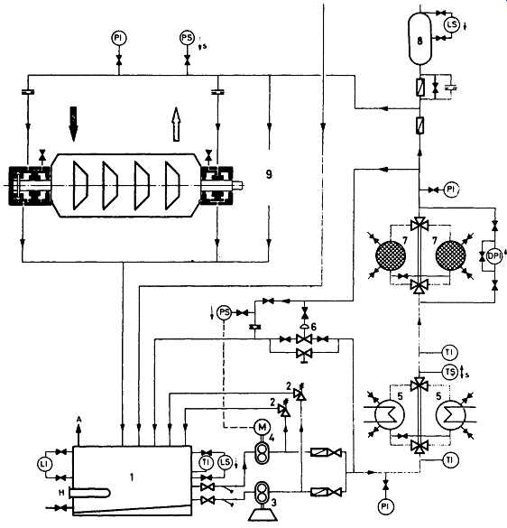
FIG. 23 Lube oil schematic for a centrifugal compressor. 1- Reservoir; 2-
safety valve; 3- main oil pump; 4 - auxiliary oil pump; 5 - cooler; 6 - pressure-regulating
valve; 7 -filter; 8 - overhead tank; 9-driver and other users; Pl-pressure
indicator; DPI-differential pressure indicator; PS-pressure switch; TI- temperature
indicator; TS- temperature switch; LI- level indicator; LS- level switch;
H- heater; A - reservoir vent. (Mannesmann Demag, Duisburg, Germany.)
The filters clean the lube oil before it reaches the lubrication points. A differential pressure gauge monitors the degree of fouling of the filters.
An overhead oil tank can be provided to ensure a supply of lubricant to the bearings in the event of faults while the compressor is being run down. A continuous flow of oil through an orifice maintains the header oil constantly at operating temperature. Should the pressure in the lube oil system fall, the nonreturn valve beneath the tank opens to provide a flow of oil.
The flow of oil to each bearing is regulated individually by orifices, particularly important for lubrication points requiring different pressures. Lube oil for the driver and other users is taken from branch lines.
When a hydraulic shaft position indicator is used, this is supplied with oil from the lube oil system.
Temperatures and pressures are measured at all important locations in the system; the readings can be taken locally or transmitted to a monitoring station.
Except for a few components, the lube oil system is a conveniently installed packaged unit supplied complete and ready for installation. Oil pumps, coolers, and filters are grouped around the oil reservoir on a common baseplate. Design and construction of the lube oil system must take into account the relevant regulations and any special requirements. One such requirement might be blanketing with inert gas; another might be the on-stream purification of lube oil by modem vacuum dehydrator units.
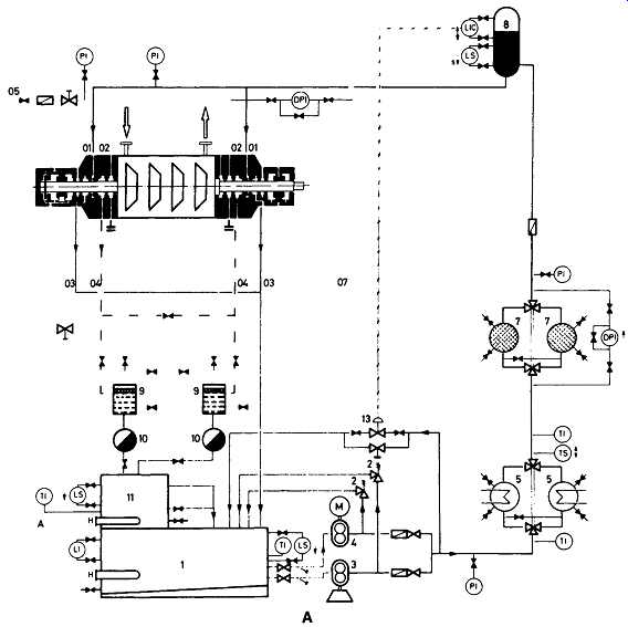
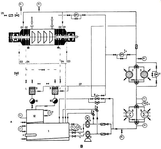
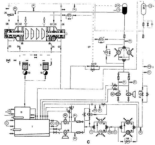
FIG. 24 Seal liquid system schematics. A
- Seal oil system for floating ring seals; B- seal oil system for mechanical
contact seals; C- lube oil system with seal oil booster system for floating
ring seals; D- seal oil system for floating ring seals with pressure reduction
for the lube oil system (combined system); I- oil tank; 2- relief valve;
3- main oil pump (high pressure); 4- auxiliary oil pump (high pressure); 5
- oil cooler (high pressure); 6 - regulating valve; 7- high-pressure filter;
8 - seal oil overhead tank; 9- demister separator; I0- condensate trap;
11- degassing tank; 12- sour oil tank; 13-level control valve; 14-pressure-reducing
valve; 15-lube oil overhead tank; 16-main oil pump (low pressure); 17-auxiliary
oil pump (low pressure); 18-oil cooler (low pressure); 19-low-pressure
filter; O1- seal oil supply; 02- buffer gas supply; 03- outer drain; 04- inner
drain (seal oil/buffer gas); 05 - buffer gas supply; 07 - reference pressure
line; 08 - lube oil supply; PI - pressure indicator; PS - pressure switch;
DPI-differential pressure indicator; TI-temperature indicator; TS- temperature
switch; LI-level indicator; LS-level switch; LIC-level controller; H-heater;
A- reservoir vent. (Mannesmann Demag, Duisburg, Germany.)
Seal Liquid System
The seal liquid system supplies the mechanical contact and floating ring seals with an adequate flow of seal liquid at all times, thus ensuring that they function correctly ( FIGs 24A and B). An effective seal is provided at the settling-out pressure when the compressor is not running.
Starting in the main oil reservoir, the medium passes to the seals via the pumps, the twin oil coolers, and the twin filters.
Instruments for monitoring the oil level and temperature are mounted on the reservoir. If necessary, the seal oil is heated; a thermostat with surface temperature limiter protects against excessively high temperatures.
Every system has a main oil pump and an auxiliary oil pump with independent drives. They are designed for a higher delivery rate than is actually needed by the seals. To protect the pumps and downstream equipment, safety valves are fitted.
Non-return valves after each pump prevent seal oil from flowing back to the reservoir through the stationary pumps.
The coolers dissipate the heat transferred to the seal oil. A temperature switch monitors the permissible temperature range.
The filters retain all impurities, the pressure drop across them being checked by a differential pressure indicator.
The floating ring seals are supplied with seal oil at a defined differential pressure above the reference gas pressure (pressure within the inner seal drain). This is schematically represented in FIG. 24A. FIG. 24C shows a lube oil system with seal oil booster arrangement; a seal oil system with pressure reduction for the lube oil portion is illustrated in FIG. 24D. The flow of seal oil is regulated by a differential pressure-regulating valve, which, if there are changes in the reference gas pressure, regulates the pressure of the seal oil, or, as shown in the diagram, by a level-control valve that maintains a constant level in the overhead tank. The oil in the overhead tank is in contact with the reference gas pressure via a separate line. The static head provides the required pressure differential. In addition, the oil in the overhead tank compensates for pressure fluctuations and serves as a run-down supply if pressure is lost. If the level in the tank falls excessively, a level switch shuts down the compressor plant. There is a constant flow of oil through the overhead tank, and this heats the oil at all times.
For the mechanical contact seal, the seal oil is kept at a constant differential pressure with respect to the reference gas by a regulating valve ( FIG. 24B). As the name indicates, the mechanical contact seal provides a mechanical seal when the compressor plant is shut down.
To prevent oil from gaining ingress to the compressor, the space between the oil drain and compression space is sealed by a flow of gas. The pressure of this sealing gas or buffer gas is above the pressure of the reference gas. A differential pressure indicator monitors the pressure differential.
The flow of seal oil divides in the compressor seals. Most of the flow returns under gravity to the reservoir. A small quantity passes through the inner seal ring to the inner drain, where it’s exposed to the gas pressure. This oil, mixed with the buffer gas, is led to the separator system. On each side this consists of a separator and a condensate trap. The separated gas is led either to the flare stack or to the suction side of the compressor. The oil flows into a tank for degassing.
If oil is used as sealing liquid and can be used again, degassing is accelerated by exposure to a partial vacuum and by heating. The oil is then returned to the reservoir.
If the oil becomes unusable, it’s led away for separate treatment.
The quantities of oil passing through the inner drain in well-designed centrifugal compressors are very small.
Temperature and pressure measuring points with local or remote reading are provided at all major points of the seal liquid system.
The seal oil system may be combined with the lube oil system if the gas does not adversely affect the lubricating qualities of the oil or provided the oil made unserviceable by the gas does not return into the oil system.
There are two methods of combining lube oil and seal oil systems. In the first of these, the oil can be raised to the pressure required for lubrication purposes and part of it then raised further to the pressure needed for sealing (booster system). Alternatively, all the oil is initially raised to the seal oil pressure and the flow of oil required for lubrication is then reduced in pressure (combined system).
Compressor Monitoring and Safety Equipment
In order to ensure the operational reliability and safety of centrifugal compressors, all major mechanical and thermodynamic parameters must be constantly scanned and evaluated. Only fast detection of changes makes possible timely intervention, thus protecting the compressor plant and the process from potentially damaging effects.
Prominent manufacturers therefore design and supply complete monitoring and instrument panels for compressor and driver. These contain all the instrumentation for monitoring, including control equipment, an alarm system, and interlock and shutdown systems.
Moreover, these manufacturers often furnish fully automatic compressor plants with automatic start/stop control for single compressor sets or, if required, including the higher-level station control facility. The latter switches the individual compressors on or off as required when such machines are operating in parallel.
The control equipment needed for compressor and driver, fittings and auxiliaries is fully taken into consideration. Installations of this kind already supplied by major manufacturers include those with air compressors in large compressed air systems, sewage treatment plants, and offshore platforms with gas compressors.
Bearing Monitors
Smooth running of the shaft can be guaranteed only by bearings that function properly. The simplest check is monitoring of the lube oil draining from the bearings; wear of or damage to the running surfaces or insufficient beating clearance mean greater friction and therefore an elevated oil discharge temperature. The high temperatures present another hazard, since they reduce the viscosity of the lube oil and hence its lubricating effect. Thermocouples, mercury thermometers, and resistance thermometers may be used for monitoring oil temperature. The permissible temperature range is limited by switching contacts; if the set limits are exceeded, an alarm is initiated or the compressor is tripped. It’s also possible to measure the bearing temperatures directly in the bearing pads.
Measurement of Vibration and Shaft Position
Mechanical vibration of shaft and casing and axial shaft displacements are important indications of possible hazard to compressor operating reliability. Modem technology renders it possible to detect even the slightest of changes in these parameters.
Shaft vibrations may be due to a number of causes: deposits or other impeller unbalances; shaft distortion as a result of thermal stresses or shock loads; changed bearing condition; effects emanating from the driver or gearing. Measurements are performed by probes that are calibrated for a certain distance between shaft and probe head. These probes produce an electrical signal proportional to the amplitude of vibration. The permissible shaft vibration depends on the speed and the rotating mass. Low speeds allow higher vibration. Apart from measuring the total level, which is the sum of the amplitudes at different frequencies, it’s also possible to analyze the vibrations on the basis of frequency. This may give a clue to the exciting frequencies or other causes of vibration.
Seismic pickups are employed for measuring casing or bearing pedestal vibrations. This method does not supply such precise results as shaft vibration measurement, but it offers the advantage of permitting measurements to be performed on running machines without having to make modifications first.
The shaft position indicator monitors the axial position of the shaft relative to the casing. The cause of axial displacement of the shaft may be wear of the thrust bearing or sudden loads that may occur when the compressor is operating in the unstable region. Detection of axial shaft shift is usually by electrical, or less frequently, by hydraulic means. Electrical measurement basically involves the same probes as are used for contactless vibration measurement.
All devices can be fitted with switches that trigger alarms or initiate shut-down of the plant to prevent damage when limit values are exceeded. Modem shut-down devices use the input from several sensors into a logic module. The machine would be automatically taken off-line if, for instance, a temperature sensor and a vibration sensor would independently confirm a violation of two setpoints.
SELECTION OF A CENTRIFUGAL COMPRESSOR
Compressor selection topics are covered in the appendices on barrel and isotherm compressors in this section, and also in the Sub-section to the section on axial compressors. Since environmental considerations play a major role in equipment selection today, this topic will be dealt with in more depth in Environmental Engineering and Management: Sustainable Development in the Power Generation, Oil & Gas and Process Industries.