AMAZON multi-meters discounts AMAZON oscilloscope discounts
IN WIRING DESIGN, THERE ARE NUMEROUS possible solutions to each problem-some good, some fair, and some poor. Experience guides designers to a solution that best suits the job, within the context of establishing the most cost-effective design, considering the project design intent and criteria.
This Section opens with a discussion of typical design criteria and continues with wiring design. An electrical design solution intended for construction must meet all the requirements of local and national building codes. In the U.S., building codes generally refer to NFPA 70, the National Electrical Code (NEC) published by the National Fire Protection Association, as the minimum standard for all electrical design, and its requirements are thereby made legally binding on the design team. The electrical design data and procedures presented in this Section, and in other sections of this book, are based upon NEC requirements and are, to the extent possible, current. However, they are intended only as informative materials. Code requirements can change fairly rapidly; the NEC, for example, is revised every 3 years. The designer is strongly advised to obtain and study the latest edition of all codes having jurisdiction, including the NEC, to ensure that a proposed electrical design meets the requirements of the current and applicable codes.
1. GENERAL CONSIDERATIONS
(a) Flexibility
Every wiring system should incorporate sufficient flexibility in branch circuitry, feeders, and panels to accommodate all reasonably probable patterns, arrangements, and locations of electric loads. The degree of flexibility to be incorporated depends largely upon the type of facility. Thus, laboratories, research facilities, and small educational buildings typically require far more flexibility than do residential, office, and fixed-purpose industrial installations. Part of designing for flexibility includes providing for building and electric service expansion, as experience has demonstrated that most facilities will grow, both physically and in electrical demand. Overdesign, however, is as bad as under-design, being wasteful of money and resources, both initially and in operation. A clear understanding of the Owner's Project Requirements can greatly assist in reaching a reasonable compromise between cur rent and future needs.
(b) Reliability
The reliability of electrical power within a facility is determined by two factors: the incoming utility service and the building's electrical system. The service record of the utility should be studied along with the economic impacts of a power outage to determine whether and to what extent standby power equipment is justified. Emergency equipment required for the safety of building occupants is established by local, state, and national building codes.
Beyond the electrical service point, the reliability of power is entirely dependent upon the wiring and distribution system. Here, too, economic studies must be made to determine the quality of equipment and the extent of redundancy (duplicate equipment) to be installed. The subject of reliability is complex, and only a few general principles are noted here.
1. The reliability of an electric system is only as good as that of its weakest element. Therefore, it may be necessary to provide redundancy at anticipated weak points in the system.
2. The electrical service and the building distribution system act together. An extremely reliable (and expensive) service is of little use if the power cannot reach the desired points of usage.
3. Critical loads within the facility should be defined to determine how best to serve them reliably. This is done by establishing reliable power paths or by furnishing individual standby power packages for such loads. The latter course is often chosen for health-care facilities and critical loads in other buildings.
(c) Safety
Although rigid adherence to the requirements of the NEC and other applicable NFPA codes ensures an initially safe electrical installation, the designer must be alert to the potential for electric hazards caused by misuse or abuse of equipment or by equipment failure. Also, attention to the physical size of equipment during design can eliminate the often-encountered hazards caused by obstruction of access spaces, passages, closets, and surfaces with electric equipment. Finally, lightning protection should also be considered under the heading of safety; this topic is discussed in Section 24.
(d) Economic Considerations
This area of concern can readily be divided into two frequently interrelated items: first cost and life-cycle cost. All other factors being equal, first cost depends largely upon whether an owner is interested in the minimum first cost or the minimum overall owner ship cost. These two costs frequently stand in inverse relationship to one another (exceptions are mentioned later). Low first-cost equipment generally results in higher energy costs, higher maintenance costs, and shorter life-with a resulting higher life cycle cost.
The electrical energy cost related to building operations is directly related to energy consumption, with one exception. That exception is the utility company's demand charge. Means for minimizing this cost are covered in detail in Section 25.13. Here, there is a coincidence, whereby a reduction to both first cost and operating costs can be achieved. Load-leveling equipment permits the electrical distribution system to be sized without consideration of coincident load peaks, thus resulting in smaller equipment that operates more efficiently- near its full-load capacity. All other reductions in electric energy cost flow directly from the corresponding reduction in energy consumption.
(e) Energy Considerations
These concerns are complex, involving consideration of energy codes and budgets, energy efficiency techniques (see Section 5), and energy control.
Buildings designed under a number of scenarios may be effectively subject to energy budget limitations (expressed in Btu/ft^2/year [kWh/m^2 per year]). Although the lion's share of this budget is taken by heating/cooling and lighting systems, the electrical distribution system is also subject to limits in some codes/standards. Most important among these is ANSI/ASHRAE/IESNA Standard 90.1, a current version of which is mandatory in all design offices. Detailed energy conservation considerations are discussed in Section 5. A discussion of the IESNA-developed Recommended Procedure for Lighting Power Limit Determination is found in Section 15.
(f) Space Allocations
The general impression that electrical equipment is small and easily concealed is accurate only for wire and conduit. Panels, motor control centers, busduct, distribution centers, switchboards, transformers, and so on can be large, bulky, noisy, and highly sensitive to tampering and vandalism. Thus, space allocations must be concerned with ease of maintenance, ventilation potential, expandability, centrality (to limit the length of runs), limiting access to authorized personnel, and noise control, in addition to the fundamental consideration of space adequacy.
(g) Special Considerations
These depend upon the nature of the facility and may include items such as security, central and/or remote controls, interconnection with other facilities, and the like.
2. LOAD ESTIMATING
When initiating the electrical system design for a facility, it is necessary to estimate the total building load in order to plan for such spaces as transformer rooms, conduit chases, and electrical closets. An estimated load is also required by the local power company well in advance of the start of construction. An exact load tabulation can be made only after the design is completed, but because this is often several months later, a good preliminary estimate is required. Such an estimate can be made from the figures given in Table 1. These values represent averages. When it appears that a building will have heavier or lighter loads because of lighting levels, a design (such as a green building) that exceeds energy codes, load-management equipment, the aggressive use of passive systems, or other factors, the values should be modified accordingly. The figures given in the individual categories should be added without application of demand or diversity factors in order to obtain the maximum load for which the building service equipment must be sized-in the absence of electric load-control (load-leveling) equipment.
(Non-coincident loads, such as heating and cooling in the same space, are not combined.) At this point in the design process, an analysis can be made to determine the feasibility of incorporating electric load-control equipment into the facility. Inputs to such a study include the utility's complete rate schedule, including all penalty clauses, a detailed analysis of the building's equipment load patterns, and any external constraints such as maximum loads imposed by power and energy budgets. Equipment load patterns must be carefully analyzed because they determine load sheddability. Thus, for kitchen equipment, load interruption may be unacceptable, but shifting of cooking time by half an hour may be quite feasible.
For HVAC equipment, building thermal inertia and pushing maximum and minimum temperature and humidity limits may permit considerable latitude without adverse effects. Also, as explained here, the degree and duration of load shedding are a function of the type of control equipment utilized.
To repeat what was previously stated-load control affects maximum demand, with only minor effect on total energy consumption. The external constraints referred to are the energy budgets recommended or required by codes, legislation, and funding bodies.
After a load-control analysis is complete, or simultaneously with such an analysis, a building energy consumption analysis must be performed.
This may be done manually, but numerous computer programs are readily available that not only increase accuracy but also permit consideration of more factors. The results of this analysis will indicate whether the target electrical energy budget is being met. If not, loads must be modified by reconsideration of proposed systems (and perhaps system design criteria), by incorporating energy conservation devices and techniques into the electrical system design, and by preparing energy-use guidelines that will be applied when the building is occupied.
Because this last item depends for success upon the day-to-day voluntary actions of the building's operators and occupants, experience has shown that it should not be considered as a major conservation factor. Ongoing building commissioning can be a powerful assist in changing this situation. Conservation measures are covered in Section 5.
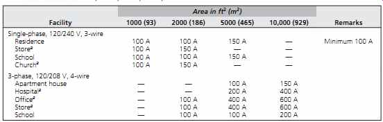
TABLE 1 Electric Load Estimating
The electrical loads in any facility can be categorized as follows:
1. Lighting
2. Miscellaneous power, which includes data processing equipment, convenience outlets, and small motors
3. Heating, ventilating, and air-conditioning (HVAC) equipment
4. Plumbing and other piping-based systems
5. Mechanized transportation equipment and fixed material-handling equipment
6. Kitchen equipment
7. Special equipment
Category 1 is covered by column II of Table 1.
Note, however, that lighting loads are carefully prescribed in ANSI/ASHRAE/IESNA Standard 90.1 and that these prescribed loads should be used where this standard has jurisdiction (which is most of the U.S.). Contradictions between requirements in applicable codes/standards must be adjudicated by local authorities before a design is established.
Consult the current version of ANSI/ASHRAE/ IESNA Standard 90.1 for details of prescribed lighting loads.
Category 2, column III, includes, in addition to receptacles and small motors, such items as desktop computers and data-processing terminals including all peripheral equipment, plus plug-in heaters, water fountains, and so on.
Category 3, column IV, includes all loads imposed by the HVAC equipment. This includes fuel pumps, boiler motors, air-handling units, exhaust fans, and so forth. Also included in column IV, for air-conditioning loads, are refrigeration compressors. This item is omitted in column V because the air conditioning utilizes absorption machines that do not use electricity for primary power. When cooling is not anticipated, the HVAC load is still appreciable because of heating and ventilating requirements. A rough estimate for the load in this situation would be two-thirds of the loads in column V.
Category 4 includes all loads associated with water and sanitary systems, including house water pumps, air compressors and vacuum pumps, sump pumps and ejectors, well pumps and fire pumps, water heaters and pneumatic tubes, plus special items such as display fountain pumps.
Also included in this category are electric loads associated with fixed piping-based systems such as cooking gas, medical gas piping, distilled water systems, and so on.
Because these loads vary widely with local conditions and with specific facility design as much as with the type of facility, an estimate cannot be made on a volt-amperes per unit area basis by type of building. Thus, no value is included in Table 1. If actual data cannot be used, it is helpful to remember that plumbing/piping electrical loads are relatively small, rarely exceeding 20% of the HVAC system electric load (although, for the most part, they are unrelated to the HVAC components).
Category 5, vertical transportation, is related to floor area in some types of buildings but not in others. A close estimate of power and energy requirements can be made by the project's elevator consultant. Lacking this, a fair estimate can be made from the data given in Sections 31 to 33. In addition to elevators, escalators, moving walkways, and ramps, these loads should include dumbwaiters, horizontal and vertical conveyors, trash and linen transport systems, automated container delivery, and fixed conveyors. These loads are readily available from a material transport consultant, who is frequently also the elevator consultant.
Category 6, kitchen equipment, is also not included in Table 1, although obviously present in all restaurants, most hospitals, and some office and religious-use buildings. The reason for this omission is that the primary power for the major load, cooking equipment, may be either gas or electric. Other large-energy-use equipment such as dishwashers can be electric, gas, or steam-fed.
Furthermore, no correlation can be made between the facility type, floor area, and load, even if electrically powered, because population and schedule are also major factors. When kitchens are planned, a kitchen consultant or other experienced planner can supply an estimate of the electric power requirements.
Category 7, special equipment, is so varied that no values can be listed. This category includes such items as laboratory equipment, shop loads, display area loads, floodlighting, canopy heaters, display window lighting, industrial loads, and so on. Data for these loads must be gathered for individual items of equipment and added to the foregoing totals.
Table 2 gives a tabulation of service entrance size in amperes, based on single- and 3-phase service for typical occupancies. These figures are intended for rough estimating purposes and should be adjusted after the design is completed.
TABLE 2 Nominal Service Size in Amperes
3. SYSTEM VOLTAGE
Several voltage systems (arrangements) are commonly available in the United States and Canada. (See NEC Article 230, "Services," for code requirements.) (a) 120-V, Single-Phase, 2-Wire
This (FIGR. 1) is used for the smallest facilities, such as outbuildings, and isolated small loads of up to 6 kVA. The load is calculated by multiplying current and voltage. For 60-A service, which is the normal limit for this type of service, no more than 50 A are usually drawn. Thus VA = 120 × 50 = 6000 VA = 6 kVA
The nominal system voltage is 120 V, although it is also referred to as 110 V and 115 V.
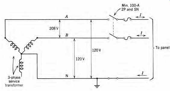
(b) 120/240-V, Single-Phase, 3-Wire
This system (FIGR. 2) is for somewhat heavier loads. The code requires that all one-family residences with six or more 2-wire circuits or a net computed load (by code calculation) of 10 kVA or more have a minimum of 100-A, 3-wire service.
Service disconnect for 100-A service would be a 100-A, 2-pole, solid neutral switch, fused at no more than 80% of the rating, or 80 A. This is usually written 100A, 2P & SN, 80AF. This service is used principally for residences, small stores, and other occupancies where the load does not exceed 80 A or 19.2 kVA. The load is calculated thus:
Although it may appear otherwise, the neutral carries no more than full-load current. Note that each "hot leg" of the 3-wire system carries line cur rent. Thus, total load can also be calculated:
load kVA = twice load on each line
Assuming a balanced 80-A load:
total kVA = 2 × 80 A × 120 V
If the loads were unbalanced with, say, 30 A in one line and 50 A in the other, the total load would be…
Actual system voltages can be 120/240, 115/230, or 110/220, although 120/240 is the accepted industry standard. Normal receptacle and lighting loads at 120 V are connected between line and neutral. Heavier loads, such as for a clothes dryer or an electric stove, are connected between phase lines at 240 V.
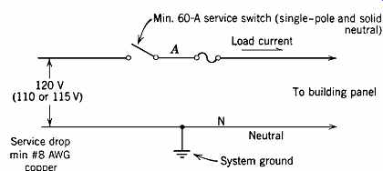
FIGR. 1 Shown is a 120-V, single-phase, 2-wire service. This is also the arrangement
of a typical branch circuit.
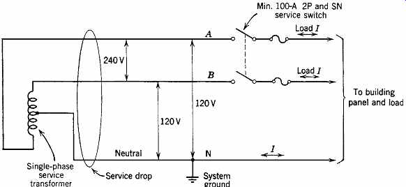
FIGR. 2 Shown is a 120/240-V, single-phase, 3-wire service. The single-phase
transformer, which is normally located on the power company's pole along a
street or road, is center-tapped to establish a neutral. The neutral connection
is always grounded.
For example, to find the line currents caused by the three loads shown in FIGR. 3:
1. 120-V, 1200-W iron, line A to neutral
2. 120-V, 1440-W hair dryer, line B to neutral
3. 240-V, 4800-W clothes dryer, line A to line B calculate
Note that the neutral only carries the unbalance of 2 A (see FIGR. 3).
Total current in line A = 20 + 10 = 30 A Total current in line B = 20 + 12 = 32 A Total current in neutral N = 2 A Total load = 120(30) + 120(32) = 3600 + 3480 = 7440 VA or Loads are 1200 + 1440 + 4800 = 7440 VA Because the loads are almost entirely resistive heating loads (small hair dryer motor and approximately a 1 6-hp [0.12 kW] dryer motor), the entire load has a power factor of almost 1.0. This, however, affects only energy calculations because equipment is sized, in general, by kVA capacity. The 120/240-V, single-phase system is derived from a center-tapped, single-phase transformer.
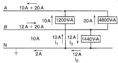
FIGR. 3 An example 120/240 V, 3-wire distribution. Note that the neutral carries
the difference in current between the A and B legs and therefore a maximum
that is equal to the current in one of the legs (when the other is zero).
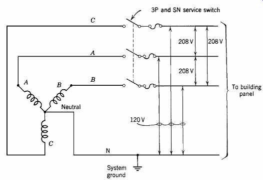
FIGR. 4 Shown is a 120/208-V, single-phase, 3-wire service. This arrangement
comprises two-thirds of the full 120/208-V, 3-phase, 4-wire connection shown
in FIGR. 5.
(c) 120/208-V, Single-Phase, 3-Wire
Although this system (FIGR. 4) appears similar to the one described in Section 3b, it is really part of a 3-phase system. It is most often found within a building that takes 3-phase service rather than constituting a service voltage arrangement. It is used to serve a load that does not require 3-phase, 4 wire but does require a voltage higher than 120 V. Calculation of loads and line currents is consider ably more complex than in Section 3b because of the 120º phase displacement between phases A and B. Here, as before, the neutral carries no more than line current, regardless of whether the system is balanced.
(d) 120/208-V, 3-Phase, 4-Wire
This system (FIGR. 5) is a widely used 3-phase arrangement applicable to all facilities except very large ones. In the latter, lengths of feeders and sizes of loads become so great that a higher system volt age is required. In this system, 120-V loads such as lighting, computers and accessories, receptacles, and so on are fed at 120 V by connection between a phase leg (FIGR. 6) and neutral. Motors larger than ½ hp (0.37 kW) and all 3-phase loads are fed at 208 V by connection to the 3-phase legs.
Single-phase, 208-V loads such as heaters are accommodated as described in Section 3c by connection between two phase legs. Such loads are often referred to as 2-pole loads, alluding to the 2-pole current breakers used to feed them.
FIGR. 5 Shown is a 120/208-V, 3-phase, 4-wire system. The neutral connection
is connected to the system ground and is not broken by the service switch.
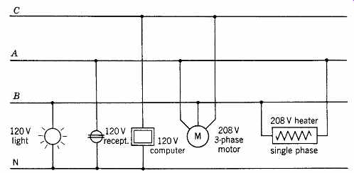
FIGR. 6 The flexibility of the 120/208-V system is illustrated; this accounts
for its wide usage. Loads are shown schematically. In practice, the loads are
fed via protective devices in the panel (omitted here for clarity). A, B, C,
and N represent the panel buses.
(e) 277/480-V, 3-Phase, 4-Wire
This system (Figs. 28.7 and 28.8) is applicable to large buildings (either horizontally or vertically) where lighting is principally fluorescent and/or high-intensity discharge (HID) and the 120-V load does not exceed one-third of the total load. It provides 277 V for fluorescent and HID lighting and 480 V for machinery. Small (3- to 25-kVA) dry-type transformers are used to step down from 480 V for 120-V loads. This system is ideally suited to multistory office buildings and large single-level or multilevel industrial buildings. Cost savings are generated by the smaller feeder and conduit sizes and smaller switchgear, which more than offset the additional cost of step-down transformers for the 120-V loads.
As an example of the economies possible with this system, consider the wiring required for a 15-kW heater. At 3-phase, 208 V:
I = 15,000 W x 208 V =42A
× requiring
No. 8 RHW wire (45-A capacity). At 480 V:
I = 15,000 W x 480 V =18A
× requiring only No. 12 RHW wire (20-A capacity).
This voltage system is also referred to as 265/460 V and 255/440 V.
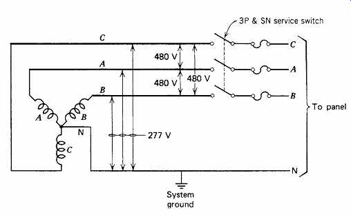
FIGR. 7 Shown is a 277/480-V, 3-phase, 4-wire service system. The system is
identical to the 120/208-V system shown in FIGR. 5 except for the voltages.
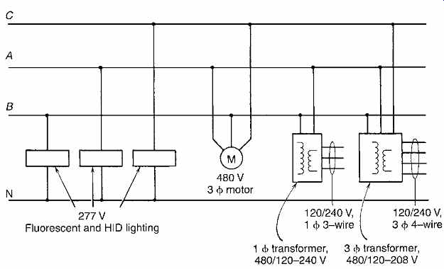
FIGR. 8 Normal load arrangement for a 277/480-V system is illustrated. The
lighting can be fluorescent or HID. Transformers, either single-phase or 3-phase,
supply 120 V for receptacles and 208 V for loads requiring that voltage.
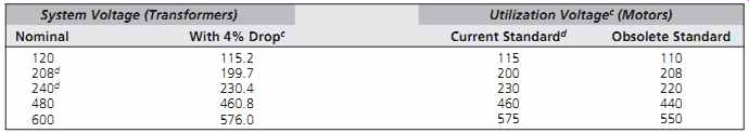
TABLE 3 Standard System and Utilization Voltages
Voltages above 150 V to ground are generally avoided in residential branch circuits but may be used in commercial and industrial facilities within the guidelines established by the NEC.
(f) 2400/4160-V, 3-Phase, 4-Wire
This system is used only in very large commercial or industrial buildings with machinery requiring these voltages. The cost of running these voltages within a building is high because of NEC requirements and the inherently higher cost of 5-kV equipment. A detailed cost and engineering analysis by an electrical engineer is required for each case. Voltages above this level are widely used in large industrial plants but are beyond the scope of this guide.
Reference was made earlier to the varied "volt ages" assigned to the same voltage system. Thus, at the lowest level, there is 110, 115, and 120 V; at the next level, 200, 208, 220, 230, and 240 V; at the next, 255, 265, and 277 V; and finally, 440, 465, and 480 V. These voltage terminology differences arise because of the historic difference between transformer voltage standards, which establish the system voltage, and motor voltage standards, which govern utilization voltage (Table 3). Present motor voltage standards are in agreement with the system voltage standards. Note the close correspondence between motor standard voltage and system voltage with a (normal) 4% feeder volt age drop. Thus, on 240- and 480-V systems, respectively, 230- and 460-V motors are suitable.
Difficulties arise in the application of 230- and 240-V motors to a 208-V system. Although motors will operate at plus or minus 10% voltage, 230- and 240-V motors should not be used on 208-V systems. Instead, motors specially wound for 200 V should be specified. A brief summary of the effects of undervoltage is given in Table 4.
4. GROUNDING AND GROUND-FAULT PROTECTION
The vast majority of secondary wiring systems are solidly grounded. The reasons for this arrangement are several and varied. Among them are:
1. To prevent sustained contact between a low voltage secondary system and a high-voltage primary system in the event of an insulation failure. Such contact could cause a breakdown of the secondary system insulation and severely endanger system users.
2. To prevent single grounds from going unnoticed until a second ground occurs, which would extensively disable the secondary system.
3. To permit locating ground faults with ease.
4. To protect against voltage surges.
5. To establish a neutral at zero potential for safety and for reference.
Points 2 and 4 are highly technical, and a full explanation is beyond the scope of this book. Point 5 requires that the neutral in a single secondary system is:
1. Never interrupted by switches or other devices
2. Connected to ground only at one point-the service entrance
3. Color-coded (in the United States) white, natural gray, or by three continuous white stripes on any insulation color other than green, along the entire conductor length, for easy recognition A typical service-grounding diagram is given in Figr. 9. Universal acceptance and use of grounded secondary 120-V systems introduces another shock hazard while eliminating the dangers described previously. This is shown in FIGR. 10a. An accidental fault within an appliance could connect the metal case of the appliance to the line. This can occur with such common devices as an electric saw, a clothes washer or dryer, or a food mixer. A person contacting the appliance housing and simultaneously a ground, such as a water pipe, would receive a nasty 120-V shock. If the contact were made with wet hands, the shock could be fatal. Unfortunately, however, until such an incident occurred, the internal fault would remain an unnoticed source of danger.
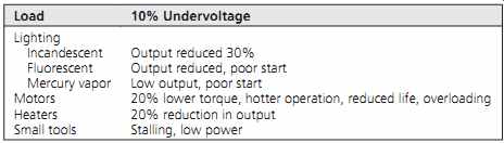
TABLE 4 Effects of Undervoltage on Utilization Equipment
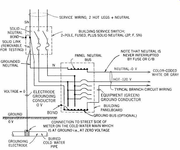
FIGR. 9 Typical service-grounding arrangement. Note that the grounded neutral
is unbroken throughout. The ground bus, if present, is separate and distinct
from the neutral bus, and both are grounded at the service entrance point.
For the sake of clarity, not all bonding connections, which are required to
ground all non-current-carrying metal parts of the electrical system (boxes,
enclosures, conduits, etc.) are shown.
To eliminate this hazard, appliance manufacturers have always recommended that appliance housings be grounded to a cold-water pipe. In addition, the appliances are supplied with 3-wire plugs: two wires connected to the appliance and the third wire to the housing. To accommodate such plugs and to provide a ground path, the NEC requires all receptacles to be of the grounding type and all wiring systems to provide a ground path, separate and distinct from the neutral conductor. The result of such wiring is shown in FIGR. 10b, where the ground current passes harmlessly through the internal fault, along the ground-wire path, and back to the panel. A person contacting the appliance housing establishes a parallel ground path. However, because this path is usually of much higher resistance than the ground-conductor path, only a very small current will flow. Wet hands materially reduce contact resistance, and shock current can increase to a dangerous level. If the ground cur rent is sufficiently high, the branch circuit breaker or fuse opens, disconnecting the circuit.
When wiring systems are installed in metallic conduit, the conduit itself or the conduit plus a separate conductor within the conduit may be used as the grounding path. The latter method, with the additional ground wire, is far preferable as explained in FIGR. 10. When nonmetallic or flexible metallic wiring (Romex or BX) is used, a separate grounding conductor run with the regular circuit conductors must be used.
All insulated ground conductors must have their covering colored green for identification as a grounding conductor. Many industrial installations install complete "green-ground" systems in an attempt to eliminate shock hazard and reduce insulation failures. This has not been entirely successful for the reason noted previously-in order to clear the ground fault, its current must be high enough to trip the branch circuit protective device.
Otherwise, the ground fault continues to "leak," unnoticed by the system's protective devices.
Unfortunately, ground faults are by nature low current, leak-type faults, because they result from weak spots in insulation, dirt accumulation, and so on. Therefore, although the shock hazard is greatly reduced by the green-ground path, the fault continues to leak and arc until it becomes hot enough to cause a major breakdown, frequently accompanied by fire.
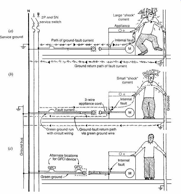
FIGR. 10 Three types of circuit arrangements. (a) A 2-wire, grounded-neutral
circuit with no means of preventing shocks from ground faults. (b) A similar
arrangement that includes a green ground wire, which considerably lessens the
danger of ground-fault shocks. Note, however, that as long as the ground-fault
current is below the rating of the branch circuit protective device (i.e.,
below 15 to 20 A), it will continue to flow within the appliance, causing overheating,
arcing, and eventual destruction of the appliance. (c) GFCIs are mandatory
for bathrooms, outdoor locations, swimming pool circuits, and other areas where
ground faults are common and particularly hazardous.
To eliminate this potentially dangerous situation, which occurs anytime there is a leak of current to ground in an electric circuit, the ground-fault circuit interrupter (GFCI) was developed (FIGR. 10c). This device compares, with extreme precision, the current flowing in the hot and neutral legs of a circuit; if there is a difference, it indicates a ground fault and the device trips out.
The rapidity of this action-approximately one half second-eliminates the possibility of a potentially dangerous shock hazard, which exists even in a properly grounded circuit, as in FIGR. 10b, and all the more so for the circuit arrangement in FIGR. 10a. The separate ground path required by the NEC (bonded metallic conduit system, green ground, or both) serves to minimize the shock cur rent taken by a person before the GFCI operates.
The device can be applied at the panel to replace a normal circuit breaker or at an individual outlet to replace a normal receptacle device. See the NEC for locations where GFCI use is mandatory, such as outdoors and in kitchens and bathrooms. It is advisable to use GFCI devices on all appliance circuits. Application to lighting circuits is generally not required because fixtures are usually out of reach and are switch-controlled.
In mixed lighting and receptacle circuits, a GFCI is best applied at the outlet that is to be protected.
5. ENERGY CONSERVATION CONSIDERATIONS
Before proceeding with a detailed description of design procedures, the many energy conservation ideas and techniques applicable to electrical distribution systems should be surveyed. This is done to provide focus on this important aspect of design, as individual techniques appear throughout the lengthy design procedure discussion and may be overlooked. The following recommendations are intended to assist with meeting a design intent to conserve energy.
1. After establishing an energy budget based upon projected loads and normal operations, set an energy reduction figure of 10% to 20% and meet this goal by using the specific techniques that follow. Annual energy consumption estimates are best made with the aid of one of the many computer programs avail able for this purpose.
2. Learn to recognize the energy-use characteristics of all equipment and systems specified (see Table 27.6). In general, select high-efficiency equipment (motors, transformers, etc.). If these are not identified as such, use materials and equipment with the lowest temperature rise, because these have the lowest losses. This generally indicates the selection of choice. When comparisons are close, a detailed analysis may be necessary.
Economic justification can be established with a life-cycle cost analysis. To avoid making a detailed cost analysis on every item, utilize one of the many available shortcut calculations for payback time.
3. Provide electric load control equipment (demand control) either as part of an over all building control system or separately.
4. In any multitenant residential building, pro vide individual user metering. Metering of heating and cooling energy should be part of the HVAC contract. All tenants should be made financially responsible for the energy they use. Exceptions to this rule would be made in the case of hotels, dormitories, and other transient facilities.
5. Where a choice of service voltages is avail able, consider the highest available. Similarly, consider the highest voltage in each class for interior distribution systems. This means 480 V in the 600-V class, 4 kV in the 5-kV class, and 13 kV in the 15-kV class.
The result will be lower line losses, smaller panelboards at the branch circuit level, and generally a lower electrical contract cost (see Section 3).
6. In any building, the maximum total voltage drop shall not exceed 3% in branch circuits or feeders, for a total of 5% to the farthest outlet, based on steady-state design load conditions.
7. Avoid the use of electric heating elements if alternatives are available. Electric heat is an inefficient use of natural resources because of the low overall efficiency of fuel-to-electricity conversion.
8. Provide metering points (for fixed or plug in meters) throughout the system to permit accurate analysis of power and energy use. Meters, both instantaneous reading and recording types, provide essential data regarding equipment loading, load patterns, load coincidence, power factor, load voltage, power demand, and energy consumption.
Analysis of these data can indicate how to program and shift loads for maximum operational efficiency and lowest energy cost. A flexible design that permits such load shifting is assumed (see item 10).
9. Include provisions for power-factor correction in the system, both at devices and at the feeder level. Then, if metering (see item 8) indicates the necessity, add capacitors as required. High power factor reduces line losses, permits maximum utilization of equipment capacity, and avoids utility penalty charges. Utilization equipment rated greater than 1000 W and lighting equipment greater than 15 W, with an inductive reactance load component, should have a power factor of not less than 85% under rated load conditions. Utilization equipment with an inherent power factor of less than 85% should be corrected to at least 90% under rated load conditions.
10. Size equipment as closely as possible to match the load. This normally results in improved efficiency and a higher power factor. Where load varies considerably-for example, between day and night or on weekends- consider splitting the loads so that part of the equipment can be switched off when the load is low and the remaining load can be fed from a "night/weekend" feeder. Such a design allows the shutdown of whole systems rather than operating at a very low load with the associated high losses and low power factor. The design must be sufficiently flexible to permit shifting of loads between feeders if measurements on the facility in operation indicate that this is desirable (see item 8). The aim is to operate equipment as closely to the rated load as possible and to de-energize lightly loaded sections by shifting load to other, partly loaded equipment.
11. Use the most efficient type of control. This means solid-state controls for motors, variable voltage, variable-frequency (VVVF) controls for variable-speed equipment (which should be considered for all variable building loads), remote switch controls for blocks of lighting, electronic control systems for elevators, and so on.
12. Arrange automatic time controls for equipment that is only needed for part of the day, such as ventilation fans, water coolers, vending machines, and computers, that might otherwise be active for 24 hours.
13. Seal all electric riser shafts to avoid heat loss by stack effect.
14. Generally select the coolest possible locations for electric equipment. Low ambient temperature (below 40ºC [104ºF]) permits the use of smaller equipment for the same load, with resultant lower cost and losses. If below grade space is available, it is well suited for this purpose.
15. Provision for future expansion should be made by means of a design that accommodates additional equipment in lieu of over sizing equipment initially. Here again, the higher cost of two pieces of equipment can normally be justified by a detailed owning and-operating (life-cycle) cost analysis using realistic cost escalation and capital cost figures.
16. Energy-conservation techniques for lighting and lighting control are found in Sections 15.17 and 16.3.
17. Energy conservation techniques for vertical transportation are found in Section 31.44.
6. ELECTRICAL WIRING DESIGN PROCEDURE
The steps involved in the electrical wiring design of any facility are outlined in this section. These steps may in some instances be performed in a different order, or two or more steps may be combined, but the procedure normally used is the following:
1. Make an electrical load estimate based upon the areas involved, available building data, and any other pertinent information (see Section 2).
2. In cooperation with the local electric utility, decide upon the point of service entrance, type of service run, service voltage, metering location, and building utilization voltage.
3. Determine, with the active input of the client, the proposed usage of all areas and information about all client-furnished equipment (including specific electric ratings and service connection requirements).
4. Determine from other consultants (such as those dealing with HVAC, plumbing, elevators, kitchens, and the like) the exact electrical ratings for all the equipment within their realm of design. This determination is often made after conferences during which the electrical consultant makes valuable recommendations to these other specialists about the comparative characteristics and costs of equipment. Such timely sharing of expertise is the foundation of the integrated building design process.
5. Determine the location and estimate the size of all required electric equipment spaces including switchboard rooms, emergency equipment spaces (or areas), electric closets, and so forth. Panelboards are normally located in closets but may be located in corridor walls or elsewhere. These decisions are necessary early in the design process to enable the architect to reserve the appropriate spaces (in appropriate locations) for electrical equipment. Once the design is developed in detail, the estimated space requirements can be checked and necessary adjustments made.
6. Design the lighting for the facility. This step is complex and involves continued interaction between the architect and the lighting designer. Coordination between daylighting and electric lighting systems is especially critical.
7. Depending upon the type of facility, it may be necessary to separate the lighting plans from the plan(s) for other devices such as signaling, low-voltage systems, and receptacles.
When an underfloor wiring system is used, it is customary to show it on a separate plan to avoid clutter and confusion. A decision about drawing conventions is made at the preliminary design stage by the project engineer.
Once the decision has been made as to how this is to be handled, the lighting fixture lay out can be made.
8. On the plan(s), locate all electrical apparatus including receptacles, switches, motors, and other power-consuming equipment. Under floor, under-carpet, and over-ceiling wiring and raceway systems would be shown at this stage, generally on a separate plan.
9. On the plan(s), locate data-processing and signal apparatus such as telecommunication outlets, network connections, phone outlets, speakers, microphones, TV outlets, fire and smoke detectors, and so on. At this stage, pro vision is also made for load control wiring, building automatic control wiring, computer control, and the like. The decision is also made as to whether intelligent panels will be used. Because some of these systems may be covered by separate contracts, the division of responsibility must be clearly defined. Often, only an empty conduit system and power outlets or sources are required in the electrical work contract. The information in this Section deals only with wiring design; further discussion of signal equipment is reserved for Section 30.
10. Circuit all lighting devices and power equipment to the appropriate panels and prepare the panel schedules. Include in this step the circuitry for emergency equipment.
11. Compute panel loads.
12. Prepare a riser diagram. This includes the design of distribution panels, switchboards, and service equipment.
13. Compute feeder sizes and all protective equipment ratings.
14. Check the preceding work.
15. Coordinate the electrical work with the other trades and with the architectural plans. This is not really a separate step, but rather a continuing process starting at step 9 and covering all subsequent stages of the work.
The background for items 1, 2, 3, 4, 6, 7, and 9 is covered elsewhere in this book. The remaining steps, that is, 5, 8, 10, 12, 13, and 15, are discussed in order in the following sections.
7. ELECTRICAL EQUIPMENT SPACES
The spaces required for electrical equipment in a facility vary greatly, depending upon the design and the nature of the building. The working spaces required around major pieces of electrical switch gear and transformers were discussed previously (see Fig. 26.28). The NEC (in Article 110) further specifies the minimum working space required in front of electrical equipment.
(a) Residences
In private residences, the service equipment and the building panelboard are generally incorporated into a single unit. The main disconnect(s) is usually installed as the main switch/breaker of the panel. A number of typical residential service-panel arrangements are shown in FIGR. 11. The panel is normally placed in the garage, utility room, or basement. To minimize voltage drop, the panel should be placed as close to the major electrical loads as practical, without sacrificing valuable space or making the panel inaccessible. Frequently, a smaller panel can be sub-fed from the main panel to feed the kitchen and laundry loads. In apartments, panels are normally placed in the kitchen or the corridor immediately adjoining the kitchen. This location is chosen so that the panel circuit breaker can act as the required disconnecting means for most fixed appliances (see NEC Article 422C).
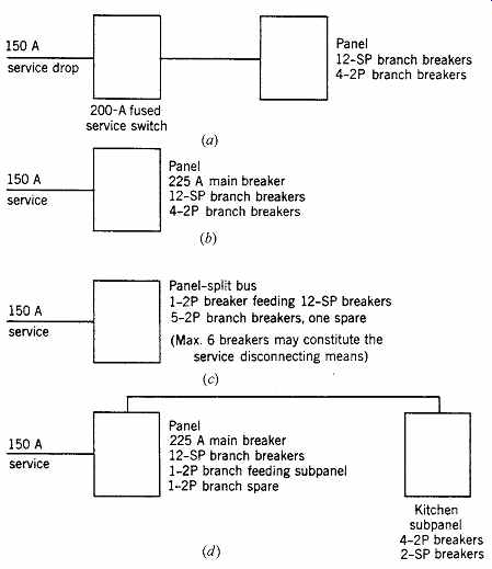
FIGR. 11 Typical 150-A service arrangements, applicable to residences and
small commercial buildings. The service switch can be a separate unit (a) or
combined with the branch circuit panelboard (b-d). The panel may be a single
unit (a, b), two units in a single enclosure, fed by separate service switches
(c), or a central panel and a sub-fed single-use panel (d)-in this case, a
kitchen subpanel.
(b) Commercial Spaces
The location of the required panelboards depends upon their type and number and upon availability of space. In the research building (for which Fig. 12 is a partial plan), lighting panels are recessed into the corridor wall because the building is only two stories high and the panels can be vertically stacked and fed by a single conduit. If this building were six or more stories high, an electric closet (see Section 8) would be advisable to accommodate the panel and riser conduits. When panels are installed in finished areas such as corridors, flush mounting is required.
To limit the voltage drop on a branch circuit in accordance with code requirements, panelboards should be located so that no circuit exceeds 100 ft (30 m) in length. If 15-A or 20-A branch circuits longer than this are unavoidable, No. 10 AWG wire should be used for runs of 100 to 150 ft (30 to 46 m) and No. 8 AWG for longer circuits. These circuits are normally wired with No. 12 AWG wire.
The laboratory between the two offices of Fig. 12 is intended to function as a self-contained unit and is therefore equipped with its own panel.
Multi-outlet assemblies, all wiring within the room, and the panel itself are surface-mounted to allow ready access to all components, to accommodate the frequent rewiring encountered in laboratories.
A main circuit breaker should be provided in such a panel to act as a main disconnect, whether required by code or not. Where panels are convenient to the load controlled, the panel circuit breakers may be used for switching.
Panels supplying large blocks of load simultaneously switched, such as auditorium house lighting, lobby lighting, large single-use office areas, store lighting, and the like, can be constructed with built-in electrically operated, mechanically held contactors to switch the entire load, with control at any desired remote location. These remote-control (RC) switches are discussed in Section 26.15. If only part of the panel circuits are so arranged (i.e., for remotely controlled block switching), a split bus panel can be used, with the RC switch controlling only that part of the panel load (FIGR. 13).
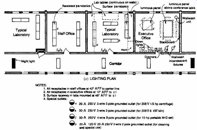
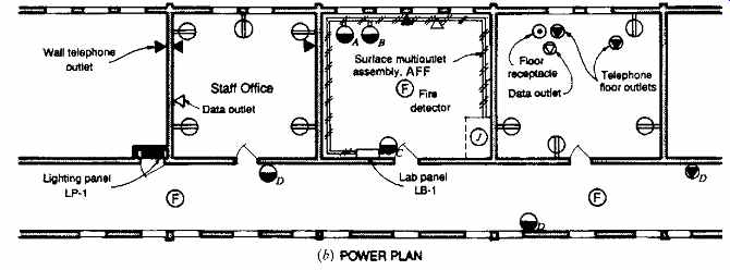
FIGR. 12 Typical floor plans for lighting and power for a section of an office-laboratory
building. Separate lighting (a) and power (b) plans are drawn for the sake
of clarity. For circuited plans, see Figs. 21 and 22. Data outlets handle
data-processing and telecommunications cabling.
Small offices, stores, and other small buildings frequently have lighting panels mounted in a convenient finished area and utilize the panels' circuit breakers for load switching. In large buildings, strategically located electric closets are provided to house all electrical supply equipment. Power panels and distribution panels are located as required by the loads fed through them.
In general, branch circuit panels, distribution panels, and switchboards are best located near the electrical load center. This minimizes feeder length and reduces voltage drop, making it the most economical arrangement.
Every completely enclosed switchgear room, emergency generator room, or transformer vault should be equipped with an emergency light source. In generator rooms, these should be battery-operated to give illumination for generator repairs in the event of generator failure during a power outage.
8. ELECTRICAL CLOSETS
When designing a building electric system, particularly for multistory construction, it is often advantageous and convenient to group the electrical equipment in a small room called an electrical closet. The shape of this space can be varied to fit the architectural requirements, and it should provide the following:
1. One or more locking doors.
2. Vertical stacking, above and below other electric closets, and located so as not to block conduits entering or leaving horizontally. Thus, locations on outside walls and adjoining shafts, columns, and stairs are poor choices.
3. Space free of other utilities such as piping or ducts passing through the closet, either horizontally or vertically.
4. Sufficient wall space to mount all requisite and future panels, switches, transformers, telephone cabinets, and communication equipment. Wall cabinet space must be coordinated with raceway connections to underfloor ducts and over-the-ceiling raceway systems.
5. Floor slots or sleeves of sufficient size for all present and future conduit or bus risers.
6. Sufficient floor space so that an electrician can work comfortably and safely on initial installation and repair.
7. Adequate illumination and ventilation.
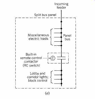
FIGR. 13 (a) Single-line diagram of a split bus panel. This design is used
when a block of load is to be controlled as a unit. The control point is either
remote, at the panel, or both. The contactor (RC switch) is electrically operated
and mechanically latched.
(b) RC switches (mechanically held contactors) are shown to the left of a bank of panels. The contactors were installed to provide photocell and timer control of department store lighting. (Photo courtesy of Automatic Switch Co.)
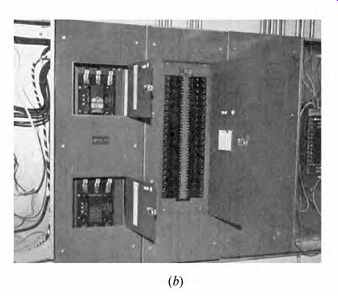
FIGR. 14 Typical electric closets with some of the usual equipment. If warranted
due to the amount of equipment, separate closets may be used for signal and
telephone conduits and cabinets. Smaller spaces may be used, depending upon
the types of equipment cabinets and their arrangement (see NEC Article 110).
In all cases, sufficient space must be provided to allow full opening of all
cabinet doors. Empty wall space for future cabinets and equipment should also
be considered.
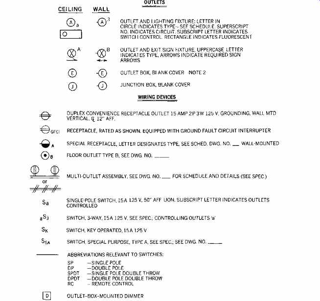
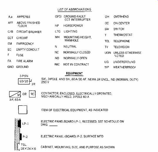
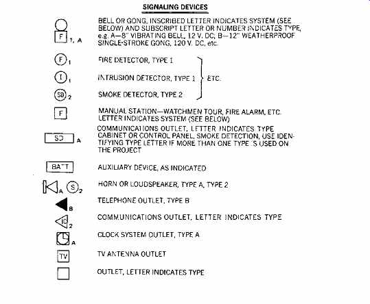
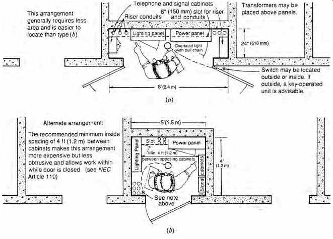
FIGR. 15 Abbreviated electrical symbol list. For a complete list, see Stein
(1997).