Home
Using Industrial Hydraulics
Applications of Computer-Aided Manufacturing
AMAZON multi-meters discounts AMAZON oscilloscope discounts
(cont. from part 1)
9. EQUIPMENT LAYOUT
Wiring devices, principally receptacles and switches, are located as required by the equipment to be served and by the anticipated use of an area.
Switches for control of lighting or receptacles are normally placed on the strike side of a door.
Other devices, such as plug-in strips on walls and special-purpose receptacles, are shown and identified. Signal outlet locations are often noted but generally remain uncircuited on floor plans, a riser or floor raceway plan being utilized to show interconnections. Signal devices include fire-alarm equipment, telephone and intercom equipment, data and communications, radio and TV outlets, and so on.
These devices may be identified by a special symbol or note where a standard symbol is not available.
As mentioned previously, lighting fixture out lets are normally placed on the same drawing as wiring devices unless the large number of the latter precludes showing the lighting without unduly cluttering the drawings. In such an event, the lighting is shown on one drawing and receptacles on another, with signals shown on the one less occupied. A ceiling or underfloor wiring system would necessitate such separation. Motors, heaters, and other fixed and permanently wired equipment are shown and identified on the receptacle drawings (also called power drawings, in contrast to lighting drawings). Equipment furnished with a cord and plug is not normally shown. However, the receptacle intended for supplying such a device is shown and identified. A typical device layout is shown in FIGR. 12. An abbreviated symbol list is given in FIGR. 15. For a complete electrical symbol list, see Stein (1997).
10. APPLICATION OF OVERCURRENT EQUIPMENT
Before beginning an explanation of circuiting, it is necessary to explain the principles underlying over current protection. As outlined in Section 26, the function of an overcurrent device is to open (interrupt) a circuit when the current rating of the equipment being protected is exceeded. All equipment must be protected in accordance with its current carrying capacity. Where ratings do not correspond exactly, the next larger standard size for protective devices up to 800 A may be used; above this, use the next lower rating (see NEC Article 240-3 for further restrictions). The following general rules govern the application of overcurrent protection:
1. Overcurrent devices must be placed on the line or supply side of the equipment being protected (FIGR. 16).
2. Overcurrent devices must be placed on all ungrounded conductors of the protected circuit.
3. In general, conductor sizes shall not be reduced in a circuit or tap unless the smallest-size wire is protected by the circuit overcurrent devices (FIGR. 17).
4. Overcurrent devices shall be located so as to be readily accessible.
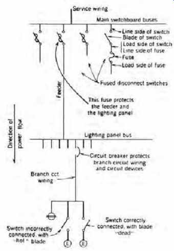
FIGR. 16 Location of overcurrent protective equipment. Protective equipment
should always be located at the point where the conductor receives its source
of supply so that when the protective device operates, the current supply is
cut off.
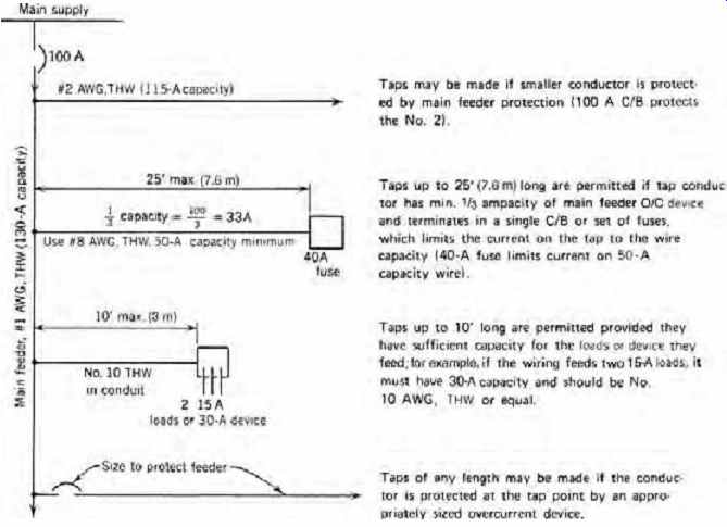
FIGR. 17 Some permissible tap arrangements. See NEC Article 240-21 for restrictions
on taps in addition to those given in the figure.
11. BRANCH CIRCUIT DESIGN
A branch circuit, by NEC definition, refers only to the circuit conductors, although for our purposes and in trade parlance it includes the protective device and the outlets served. Such circuits may be the multioutlet general-purpose type (FIGR. 18a), the multioutlet appliance type (FIGR. 18b), or the single-outlet type intended for a specific piece of equipment (FIGR. 18c). The multioutlet types are limited to 50 A in capacity, whereas the single outlet type is governed in size only by the requirements of the item being served and may be 200 A or 300 A in size.
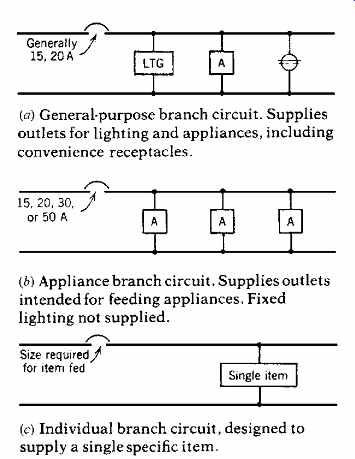
FIGR. 18 Branch circuit types. See NEC Article 210 for detailed descriptions.
In its simplest form, a branch circuit comprises only two circuit wires. However, multi wire branch circuits carrying 2- to 3-phase wires plus a neutral are also widely used. Generally, each branch circuit should be sized for the load connected to it plus the load expansion that is expected. These general rules of good practice should be followed:
1. In all but the smallest installations, connect lighting, convenience receptacles, and appliances on separate (groups of) circuits, although this is not an NEC requirement.
2. General-purpose branch circuits should be 20 A and wired with No. 12 AWG wire. Switch legs may be No. 14 AWG if the lighting load permits and the wiring meets the tap requirements of NEC Article 240-21.
3. Limit the circuit load on 15-A and 20-A circuits to the values shown in Table 5. This provides the required building load expansion capability in the branch circuitry; that is, bringing the loads on the branch circuits up to maximum allows additional building loads to be absorbed.
Because it is not always economical or feasible to expand existing circuits, however, panels are always equipped with spare breakers. These can also be utilized to pick up building load expansion, or the user may use a combination of the two techniques, expanding some existing circuits and adding new ones. Because lighting and specific devices are circuited according to their nameplate ratings, the only circuitry item left to the judgment of the designer is the number of convenience receptacles per circuit. The NEC specifies that plug outlets (convenience receptacles) be counted, in totaling loads, at 1.5 A each unless included in the load for general lighting. This point requires some clarification. The receptacle load for general illumination in dwellings is included in the 3 V-A/ft 2 (32.3 V-A/m^2) specified by NEC Table 220-3(a) and found in Table 1.
This is because receptacle outlets on general illumination circuits are assumed to supply illumination (i.e., lamps), and are therefore necessarily included in the lighting load. Application of the 1.5-A (180 V-A) per outlet criterion to such outlets would, in the opinion of the NEC, unnecessarily limit the number of outlets permitted on such circuits.
The same is true for appliance circuits. On both of these types, according to the NEC, the number of receptacle outlets is not limited. On 15- and 20-A receptacle circuits, which are neither general illumination nor small appliance branch circuits, the number of outlets is limited to 10 (1800 V-A) on a 15-A circuit and 13 (2340 V-A) on a 20-A circuit by applying the 1.5-A per outlet criterion.
It appears that the distinction between circuit types is not completely clear, and that good practice dictates the limitation of convenience receptacles per circuit to a considerably smaller number. Thus, following the guidelines of Table 5 of 9- and 12-A loading on 15- and 20-A circuits, respectively, this approach would yield.
15-A circuit:
9A 1.5 A per outlet
= 6 outlets s per circuit 20-A circuit:
12 A 1.5 A per outlet
= 8 outlet ts per circuit
These values must be used judiciously. If the devices to be energized are small, these quantities may be used. Such would be the case in a business office, where only an electric pencil sharpener or a desk lamp (100 V-A) would be plugged in. However, for computer-equipped offices, service and repair facilities, and the like, plan for no more than four receptacles on a 20 A circuit-and preferably two or three receptacles should be used on a 15-A circuit. Of course, diversity of use is an all-important factor, and the more accurately it can be estimated, the better the design result.
TABLE 5 Recommended Branch Circuit Loads (coming soon)
FIGR. 18 Branch circuit types. See NEC Article 210 for detailed descriptions.
TABLE 6 Branch Circuit Requirements (coming soon)
A further note of caution is in order: receptacles should be arranged, if at all possible, so that the loss of a single circuit does not deprive an entire area of power. That is, for the sake of reliability, circuitry should be alternated to give each space access to parts of different circuits.
NEC Table 210-24 specifies certain requirements for conductors, devices, and loads permissible on general-purpose branch circuits. These are excerpted and summarized in Table 6.
12. BRANCH CIRCUIT DESIGN GUIDELINES: RESIDENTIAL
1. The NEC (1999 edition) requires for residences sufficient circuitry to supply a load of 3 V-A/ft 2 (32.3 V-A/m^2) in the building, excluding unfinished spaces such as porches, garages, and basements. Using Table 5, which already includes a 20% derating of circuits to provide for continuous loading, this works out to 480 ft^2 (45 m^2) on a 15-A circuit (1440 V-A) and 640 ft 2 (60 m^2) on a 20-A circuit (1920 V-A). Allowing for some expansion, such as a finished basement or enclosing a porch to expand the living area, results in a good-practice recommendation of 400-480 ft^2 (37-45 m^2) per 15-A circuit and 530-640 ft^2 (49-60 m2) per 20-A circuit.
These good-practice figures normally pro vide enough circuits for all but the most heavily loaded residences. If actual design analysis indicates the need for additional circuits, however, they clearly must be pro vided. The illustrative examples in NEC Section 20 are based on absolute minimum requirements.
2. The NEC (Article 210-11) requires a minimum of two 20-A appliance branch circuits (FIGR. 18b) to feed all the receptacle out lets in the kitchen, pantry, breakfast, and/ or dining room and similar areas, and only these outlets. This is because any receptacle in these areas is a potential appliance out let and must be fed and circuited as such.
Permanently installed appliances such as a food disposal, dishwasher, fan hood, and the like may not be connected to these appliance circuits. An exception is made to permit clock outlets to be fed from these circuits. Further more, the NEC requires that all kitchen out lets intended to serve countertop areas must be fed from at least two of these appliance circuits (these circuits may also feed appliance outlets in the other spaces specified previously). Thus, not all countertop work space will be deenergized by the failure of a single circuit.
Although the code does not limit the number of appliance outlets to be wired into each circuit, good practice dictates that these receptacles be circuited with no more than four such outlets per 20-A circuit. This in turn usually requires more than the code minimum of two appliance circuits. Among other requirements, the NEC states that for kitchen and dining areas:
• No point on a wall behind a countertop shall be more than 24 in. (610 mm) from an outlet.
• All countertop convenience receptacles shall be of the GFCI type.
3. Locations utilized primarily or frequently for workshop-type activities, such as garages, utility rooms, and basements, should be pro vided with receptacles wired in appliance type circuits (i.e., 20-A receptacles on 20-A circuits), with no more than four such receptacles to a circuit. Receptacles in garages, sheds, crawlspaces, below-grade finished or unfinished basements, and outdoors must be of the GFCI type. (For exceptions to this GFCI rule, see NEC Article 210-8.)
4. Additional circuits similar to appliance circuits (no fixed lighting outlets) should be furnished to supply one outlet in each bedroom of a house that is not centrally air-conditioned.
Such outlets are intended for window air conditioners. (Good design practice may provide a window arrangement, attic ventilation, insulation, sun screening, and the like that can reduce the demand for these noisy energy users.)
5. The NEC requires that at least one 20-A appliance circuit supply the laundry outlets only.
This requirement is good practice. If an electric clothes dryer is anticipated (and it should be unless it is definitely known that a gas dryer will be used), an individual branch circuit (distinct from the laundry outlets circuit(s) and rated for the load) should be supplied to serve this load via a heavy-duty receptacle. (Facilities for hanging clothes should be provided for those who prefer not to consume electrical energy on this simple task.)
6. Layout convenience receptacles so that no point on a wall is more than 6 ft (1.8 m) from an outlet. Use 20-A, grounding-type receptacles only. Do not combine receptacles and switches into a single outlet except where convenience of use dictates high mounting of receptacles.
7. Circuit the lighting and receptacles so that each room has parts of at least two circuits.
This includes basements and garages.
8. Avoid placing all the lighting in a building on a single circuit.
9. Supply at least one 20-A wall-mounted receptacle adjacent to each bathroom lavatory (sink) location. Such receptacles must have GFCI protection. They should be fed from a 20-A circuit that energizes only such bath room receptacles. Bathroom lighting, exhaust fan, heaters, or other outlets should not be connected to the bathroom receptacle circuit.
10. Provide at least two GFCI-protected and weatherproof receptacles on the outside of the house, one in front and one at the rear. Switch control of the outside receptacles from inside the house is a convenience.
11. In rooms without overhead lighting, provide switch control for one-half of a strategically located receptacle that is intended to supply a lamp (see FIGR. 19 for the wiring arrangement in such a case).
12. Provide switch control for closet lights. Pull chains are a nuisance (but are considerably cheaper).
13. In bedrooms, supply two duplex outlets at either side of the likely bed location to accommodate electric blankets, clocks, radios, lamps, and other such appliances.
14. A disconnecting means, readily accessible and within sight of the controlled item, must be provided for electric ranges, cooktops, and ovens. It is good practice to utilize a small kitchen panel recessed into a kitchen wall to control the large kitchen appliances and provide the required disconnecting means.
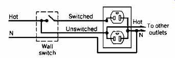
FIGR. 19 Split wiring of a duplex receptacle. The upper half is switch-controlled;
the lower half is "hot" all the time. This allows wall switch control
of a lamp or another device while keeping part of the receptacle live for independent
use. Notice that the receptacle is mounted with the grounding pole at the top.
This is the safest way to install receptacles because a metallic item such
as a paper clip falling on an inserted cap will contact the ground pole only.
15. Perimeter lighting, sensor control, and manual override can do much to lessen vandalism and discourage prowlers.
16. To accommodate the very rapidly increasing number of persons who work at home (either full- or part-time) every study and work room or, in their absence, every large master bed room should be electrically equipped to double as a home office. This room or area should be supplied minimally with these electrical ser vices:
• Six duplex 15-A or 20-A receptacles connected to at least two different circuits, one of which should serve no other outlets. All of these receptacles should be equipped with appropriate surge suppression.
• An additional separate insulated and isolated ground wire, connected only at the service point, should be run to the box(es) containing two of the receptacles required in the preceding point, and there terminated, clearly marked, and labeled. These grounds are intended for possible use with isolated ground (IG) receptacles, if it is found that the normal receptacles are too electrically noisy.
• Two telephone jacks in recessed boxes should be provided in the area. In addition, an empty ¾-in. (19-mm) conduit from the telephone entry service point to an empty 4-in. (100-mm) square box in the area should be provided. An appropriate surge suppressor must be provided for the incoming telephone service lines.
• For lighting design of this area, refer to the discussion on visual display terminal (VDT) lighting in Section 16.
A tabulation of residential electrical equipment, including recommended circuit and receptacle descriptions, is shown in Table 7. A complete residential wiring plan for a small house is shown in FIGR. 20. Although residential plans are frequently left uncircuited, a completely circuited lay out is shown here for informational purposes. The plan does not show the electrical equipment recommended for a home office that is described in item 16 for two reasons:
1. The plan is so compact that there is no single preferable location for the numerous outlets required.
2. Adding the required outlets to any selected area would clutter the plan to the point of illegibility.
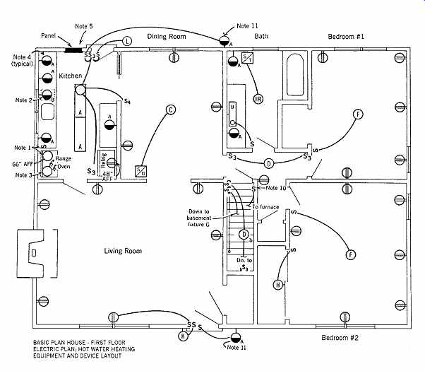
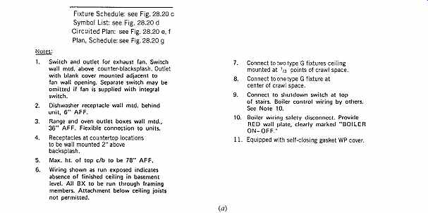
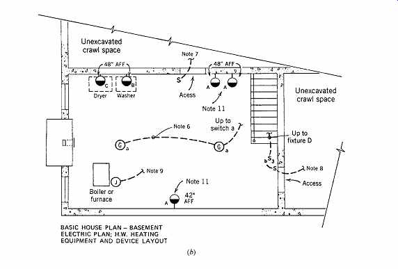
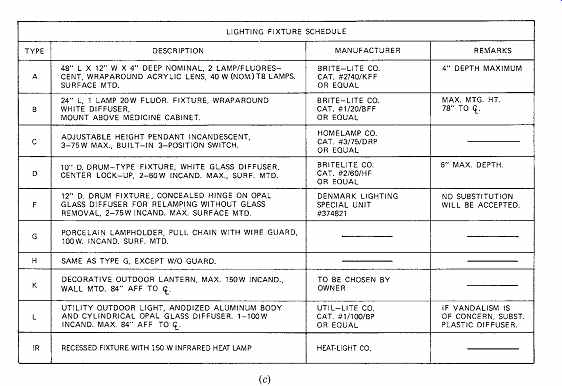
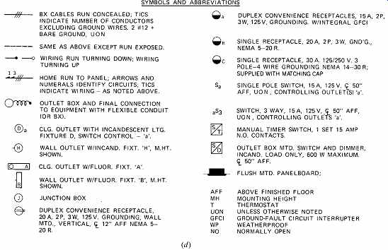
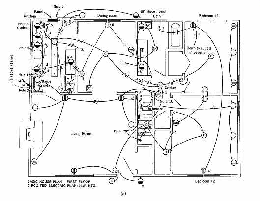
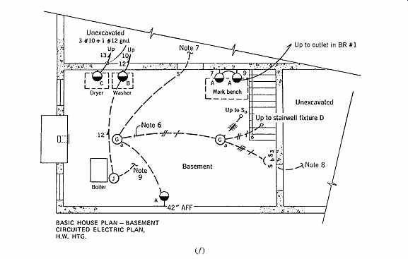
FIGR. 20 Electrical plan of a small house. (a) Layout of lighting and electrical
devices for the main floor. (b) Layout of lighting and electrical devices for
the basement. (c) Lighting fixture schedule. (d) Symbols and abbreviations.
(e) Circuited plan, main floor of house. (f) Circuited plan, basement. (g)
Panel schedule for the house.
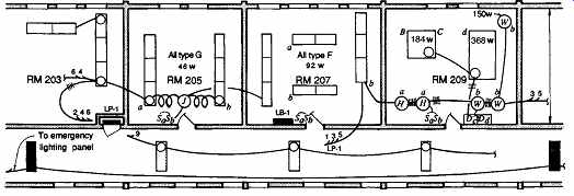
FIGR. 21 Alternative methods of circuiting are shown in different rooms. Room
205 shows the actual junction box location, with flexible connections to the
box at each fixture. Room 207 shows circuit numbers and switch designations
only; the placement of junction boxes is understood, and conduit runs are omitted
for clarity and because they usually are not representative of the actual field
installation. Room 209 shows an outlet box at each fixture, with schematic
conduit connections. All of these methods are in common use.
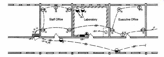
FIGR. 22 Typical receptacle circuiting of several rooms in an office-laboratory
building. Lighting (see FIGR. 21) and power (receptacles) are shown on separate
plans to avoid crowding. See FIGR. 15 for symbols and FIGR. 12 for notes. Lighting
in offices is recessed; lighting in labs is surface-mounted for flexibility.
Note the double circuiting of the type-D receptacles.
13. BRANCH CIRCUIT DESIGN GUIDELINES: NONRESIDENTIAL
TABLE 7 Load, Circuit, and Receptacle Chart for Residential Electrical Equipment
(a) Schools
Because schools comprise an assembly of varied use spaces, including instruction, lab, shop, assembly, office, and gymnasium, plus special areas such as swimming pools, photographic labs, and so on, it is not possible to generalize on branch circuit design considerations except for the following:
1. To accommodate the audio-visual equipment frequently used in classrooms, 20-A outlets wired two to a circuit should be placed at the front and back of each such room. A similar receptacle, wired six or eight to a circuit, should be placed on each remaining wall.
2. To accommodate computers, a detailed layout of the space is required showing the proposed computer locations. A two-section surface mounted or recessed raceway on the wall behind the computers should be provided. The power section should have two duplex 20-A receptacles at each computer station, wired on alternate circuits. The second section of the raceway is intended for low-voltage wiring, such as network cabling, and wiring to computer peripherals. Providing for good cable management can substantially improve the appearance and maintainability of this critical area.
3. Switching for lighting should provide:
• High-low levels for energy conservation and to permit low-level lighting for screen viewing. With fluorescent lighting, this can be accomplished by alternate ballast wiring and switching, thus avoiding the high cost of dimming equipment. The multiple modes of classroom use must be considered when establishing switching scenarios.
• Separate switching of the lighting fixtures on the window side of the room, which is often well lit by daylight. Control should be initiated automatically by a photocell (see Section 16.3).
4. Provide appropriate outlets for all special equipment in labs, shops, rooms with cooking activities, and the like.
5. Use heavy-duty devices and key-operated switches for public area lighting (corridors, etc.), plastic instead of glass in fixtures, and vandal proof equipment wherever possible. All panels must be locked and should be in locked closets.
6. The NEC requires sufficient branch circuitry to provide a minimum of 3 V-A/ft 2 (32.3 V-A/m^2) for general lighting in schools (refer to NEC Article 220). Unlike the value for residential occupancy, this figure does not include receptacles. Receptacles are calculated separately at 180 V-A each for ordinary convenience outlets.
(b) Office Space
1. In small office spaces (less than 400 ft 2 [37 m^2]), provide either one convenience outlet for every 40 ft 2 (3.7 m^2) or one outlet for every 10 linear ft (3 m) of wall space, whichever is greater. In larger office spaces, provide one outlet for every 100 to 125 ft 2 (9.3 to 11.6 m^2) beyond the initial 400 ft 2 (37 m^2). These outlets are intended for miscellaneous electrical devices, in addition to anticipating the constantly increasing number of data system accessories. In addition, provide at every desk (on an adjacent wall, in a "power pole," or in the floor) at least one duplex 20-A receptacle for a computer. These receptacles should be circuited at no more than six to a 20-A branch circuit, and less if the specific equipment to be powered so dictates. Figure 28.21 shows one possible circuiting arrangement for the room layouts shown in FIGR. 12.
Although other arrangements are possible, the net result is the same (see also FIGR. 22).
2. Corridors should have a 20-A, 120-V outlet every 50 ft (15 m) to provide power for cleaning and waxing machines.
3. As with all nonresidential buildings, convenience receptacles are figured at 180 V-A each.
4. Only specification grade equipment should be used.
(c) Industrial Spaces These areas are so specialized that no meaningful general guidelines can be given.
(d) Stores In stores, good practice requires at least one convenience outlet receptacle for every 300 ft 2 (28 m2) in addition to outlets required for loads such as lamps, show windows, and demonstration appliances.
14. LOAD TABULATION
While circuiting loads, a panel schedule is drawn up that lists the circuit numbers, load descriptions, wattage (actually, volt-amperes), and the current rating and number of poles of the circuit-protective device feeding each circuit. Spare circuits are included to the extent that the designer considers them necessary and consistent with design intent (including budget), but normally no less than 20% of the number of active circuits. Finally, spaces are left for future circuit breakers in approximately the same quantity as the number of spare circuits, but always so as to round off the total number of circuits.
Panelboards are normally manufactured with an even number of poles. Thus, if a panel had, with spares, 21 poles, the designer would ask for (at least) three spaces, to give a 24-circuit box. A typical panel schedule is shown in FIGR. 23, which serves the laboratory of Figs. 28.21 and 28.22.
In calculating panel loads, the following rules apply:
1. Each specific appliance, device, lighting fixture, or other load is taken at its nameplate rating, except certain kitchen and laundry appliances for which the NEC allows application of a demand factor (see NEC Article 220).
2. Each convenience outlet, in other than residential spaces, is counted as 1.5 A (180 V-A).
3. Loads for special areas and devices such as show window lighting, heavy-duty lampholders, and multioutlet assemblies are taken at the figures given in NEC Article 220.
4. Spare circuits are figured at approximately the same load as the average active circuits (1200 to 1500 V-A).
5. Spaces are not counted in the load.
6. Continuous loads such as lighting are calculated at 125% of their actual value. See NEC Articles 210-19(a) and 210-20(a), which refer to load calculations for conductor sizing and feeder overcurrent protection, respectively, for combinations of continuous and noncontinuous loads. These calculations apply to panel load calculations as well and are best accomplished by adding 25% to the panelboard load, as shown in FIGR. 23.
In calculating total panel loads, as shown in FIGR. 23, no demand factor may be applied except as specifically stated in the NEC (see NEC Articles 220-11 and 220-13). This is true despite the knowledge that most often the usage will be such that the average load will be lower than the maximum demand (see Section 17 for multi panel feeders). If it is known that certain loads will not or cannot be used simultaneously, the load total should reflect only the larger of the two. Thus, heating and cooling loads are generally not concurrent. Nor is building night floodlighting concur rent with the business office load, but it may be with general interior lighting. Note in FIGR. 20g that 2-pole loads (208 single-phase) appear in two columns. Similarly, 3-phase loads would appear in three columns. Also, note that the phase loads are not equal. It is the responsibility of the designer (or contractor) to circuit the loads so that the phases are as closely balanced in load as possible. If this is not done, one phase will carry considerably more current than the others. Because the panel feeder must be sized for the maximum phase current, this may lead to an oversized feeder and therefore a waste of money.
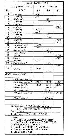
FIGR. 23 Schedule for lighting panel LP-1 (see FIGR. 22).
Once the loads have been tabulated, balanced, and totaled by phase, the maximum current is calculated. A portion of the spare capacity available in the branch circuits is added to the total as the basis for the calculation of the feeder load. This spare capacity, shown in Table 5, is between 25% and 50%. The exact amount to be initially added in feeder sizing is developed in the ensuing discussion.
15. SPARE CAPACITY
Load calculations for residential occupancies and other spaces are detailed in NEC Article 220, and examples are given in Section 20 of the NEC. Because these calculations are specialized (but routine) and are covered there in detail, they are not repeated here. Code requirements, it must be remembered, are minimum; a design solution to meet a client's needs often exceeds these basic requirements.
Once the panel load totals have been determined as detailed previously, the next step is to size the conductors feeding the panel. To do this, an examination of the spare capacity of the panel and of the feeders is necessary in order that the system design be consistent, giving equal capacity for future growth in all of its components. Considering the panel circuitry first, let us examine the effect of load expansion, including spares and spaces (Table 8).
As noted in Section 11, spare capacity is built into the branch circuitry and into the panels.
Most often, expansion is accomplished by additional loading on some circuits and by adding new circuits via spare circuit breakers in the panel. Table 8 gives the ultimate capacity of the panel-that is, fully loaded circuits and fully utilized spares and spaces. Because this ultimate capacity is rarely achieved, panel feeders need only be sized for initial loads as detailed in Section 14, and provision made for rewiring to meet anticipated expansion by one of the techniques listed in Section 16.
These results can be summarized as follows: For panels in buildings expecting limited expansion, for which branch circuits are loaded to 80% of capacity (25% branch circuit expansion; see Table 5, note e), the ultimate panel load without new conduit work (i.e., merely by filling out circuits), is 1.5 L, or 50% beyond the initial load. By adding breakers in the spaces, this load can be expanded to 75% beyond the initial load. The corresponding figures for panels that are lightly loaded (66% capacity, i.e., 50% branch circuit expansion, as in Table 5, note f ), in anticipation of considerable load growth, are 80% to 110%, respectively. These results are summarized in Table 8.
TABLE 8 Panel Initial and Expanded Loads
16. FEEDER CAPACITY
To achieve economy, the panel feeder must accommodate the initial load plus some portion of the future load. Spare capacity in feeders (to accommodate a considerable portion of the panel spare capacity, as shown in Table 8) is provided by one or more of the following procedures:
1. Provide feeder (and conduit) capacity initially to handle the entire eventual load. This method is the most expensive, requiring an initial out lay for (potentially) no return, and is rarely used.
2. Provide feeder capacity for the initial load plus spare capacity, with properly sized conduit.
Conduit is sized for type THW or RHW with out covering. This method yields limited spare capacity.
3. Provide feeder capacity for the initial load plus spare capacity, with conduit oversized by one size. Size conduit for type THW wire, which is very widely used because of its attractive price and excellent electrical properties. Some additional costs are entailed here.
If the initial wiring is done with type TW wire, the effect is approximately the same as that of oversizing the conduit by one size and wiring initially with THW wire. This is the result of the lower ampacity rating of TW com pared to THW, resulting in a larger conduit size for the same initial ampacity. Exact figures for each can be worked out with the help of Tables 2A, and 2B (prev. section), and conduit capacity in Table 9, or by using the tables in NEC Article 310 and Section 20.
4. Provide feeder capacity for the initial load plus spare capacity and oversize conduit by two sizes. This yields most of the capacity necessary in facilities anticipating large expansion.
5. Provide for the initial load plus spare capacity, and install an empty conduit for future use. This method is expensive because of the high conduit cost and is advisable only infrequently.
In approaches 2, 3, and 4, the future capacity beyond that initially supplied is handled by the use of larger-gauge wire in the existing conduit. To examine exactly what these alternatives provide in spare capacity, Table 10 tabulates the maximum ampacity of various sizes of conduits and the future capacity obtainable. Table 9 is taken directly from the NEC. Note from Table 10 that simply by rewiring, up to 30% additional capacity can be obtained, whereas if the conduit had been oversized, the additional capacity would be 35% to 146%.
Answering the question of how large to make the feeder for a given panel load requires balancing the future panel load, the initial cost of feeder, and the future capacity of existing conduit. It is best to avoid the installation of empty conduits because this is expensive. Rewiring, however, is relatively inexpensive, and oversizing conduit is the method of choice if rapid expansion is anticipated.
TABLE 9 Maximum Number of Conductors in Trade Sizes of Rigid Metal Conduit
TABLE 10 Maximum Wire and Ampacity of a Conduit, and Ampacity Gain on Rewiring
Referring to Table 10, note that normal design uses THW cable. Design with T or TW is, in effect, a first step in oversizing conduit and is generally not economical. The second step is a deliberate oversizing of conduit that results in much increased conduit ampacity, as reflected by the figures in the table. Using these values in practice requires that the designer juggle cable and conduit costs against anticipated load growth to arrive at the most economical long-term solution. Applying these numbers to concepts previously developed, suggests:
1. Buildings designed for 25% branch circuit expansion (see Table 5) have a panel capacity of 1.75 times the load (Table 8). If it is desired to design the panel feeder to carry the full expansion possible, then calculate the feeder on the basis of panel load plus 20% spares and oversize the feeder by 20%. This gives a feeder capacity of:
1.20 × 1.20 = 1.44 × initial load
Source: Extracted from the National Electrical Code.
Table 10 indicates that rewiring adds an other 20% on average. This gives 1.20 × 1.44 = 1.73 × initial load which corresponds very closely to the 1.75 desired.
2. For a building with 50% branch circuit expansion, utilizing the full panel space capacity creates an ultimate panel capacity of 2.1 times the initial load (see Table 8). This is accomplished as follows: Oversize the feeder by 15% and oversize the conduit by one size. The latter step gives an average expansion of 65%. Therefore, feeder capacity = 1.15 × 1.20 × 1.65 = 2.3 which is approximately the desired figure.
If, as in the case of laboratories, more than 100% expansion is anticipated (see Table 1), conduit should be oversized by two sizes and initial wiring oversized by approximately 25%. Feeders thus arranged will handle the new panels required to meet the anticipated expansion.
Two factors should be carefully noted here.
First, the smaller conduits offer the largest expand ability, although, in dollars per amperes, they are more expensive. Second, in order to take advantage of spaces in a panel, conduit stubs should be taken from the panel and extended into suspended ceilings (or another procedure used to make the panel circuitry easily accessible in the future).
17. PANEL FEEDER LOAD CALCULATION
EXAMPLE 1 Refer to FIGR. 23. The panel is for a laboratory/office area. Because substantial expansion is anticipated, circuitry follows the bottom section of Table 5. The ultimate panel load would be 26 circuits at 1920 V-A = 50 kVA = 138 A. Thus, the initial feeder is sized for 115 A (4 #2 THW, 1¼ in. C ), but rewiring with XHHW will allow as much as 150 A in the same conduit. A 225-A frame circuit breaker is chosen initially because eventually the trip will be raised to 150 A.
The NEC in Article 220 specifies minimum volt-amperes per unit area (V-A/ft^2 [V-A/m^2]) figures for various occupancies, for lighting, and for miscellaneous power loads. Proper design procedure therefore requires that after detailed design of an area, the actual loading should be compared to these minima, and the larger of the figures, concerning the number of circuits and feeder load, should be used. An example will help to make this clear.
EXAMPLE 2: Assume a single floor of an office building of 100 × 200 ft (30.5 × 61 m). Assume also that 15% of the area is corridor and storage, equally divided between the two. Calculate the load and feeder size. Assume a good-grade speculative construction venture.
SOLUTION
Office space = 85% of 20,000 ft 2 (1860 m^2)
= 17,000 ft 2 (1581 m^2)
Corridor and storage
= 15% of 20,000 ft 2 (1860 m^2)
= 3,000 ft 2 (279 m2) The NEC specifies a minimum of 3½ V-A/ft 2 (37.7 V-A/ m2) for lighting and 1 V-A/ft 2 (10.8 V-A/m2) for miscellaneous receptacles in office space. It further specifies
½ V-A/ft 2 (5.4 V-A/m2) minimum for corridors and
¼ V-A/ft 2 (2.7 V-A/m2) for storage. Therefore:
Lighting
Office load: 17,000 × 3½ = 59.5 kVA (1581 × 37.7) = 59.5 kVA
Corridor: 1,500 × ½ = 0.74 kVA (139 × 5.4) = 0.74 kVA
Storage: 1,500 × ¼ = 0.38 kVA (139 × 2.7) = 0.38 kVA
Minimum lighting load: = 60.6 kVA
Receptacles 17,000 × 1 V-A/ft^2 = 17 kVA (1581 × 10.8 = 17 kVA)
These values would then be compared to the actual design loads. Receptacles are counted at 180 V-A each, as noted in Section 14, item 2. If the code minima exceed the design load (as they well may if lighting is carefully designed), panels must be equipped with sufficient additional circuits to make up the difference. The number of such circuits is up to the designer, because circuit loading is not specified.
For instance, suppose that the lighting design was accomplished at 2 V-A/ft^2 (21.5 V-A/m^2). Panel circuits would have to be provided for the additional 1½ V-A/ft^2 (16.2 V-A/m^2) as follows:
17,000 ft 2 × 1.5 V-A/ft^2 = 25.5 kVA (1581 × 16.2 = 25.5 kVA)
Assuming a 30% to 50% future load expansion, we would circuit the lighting loads at approximately 1300 V-A per circuit. Therefore, we would provide 25,500 V-A 1,300 V-A = 20 additional circuits.
With respect to the minimum feeder load, the NEC specifies that it be increased by 25% if loads are continuous (3 or more hours). This requirement allows for breakers to heat up in panels while carrying a continuous load and is waived for circuit breakers that are ambient compensated-that is, are rated to carry 100% load. Because we have established 80% of the breaker rating as the maximum load, we have already accounted for this factor in circuitry but must utilize it in the feeder calculation. Assuming that the code minima are the design loads, then, for feeder calculation:
Lighting load = 60.6 kVA × 125% = 75.75 kVA
Receptacle load as given = 17.0 kVA
Minimum feeder load = 92.75 kVA 25% future load = 23.2 kVA Design feeder load = 116 kVA Because this load would be divided among several panels, the building electrical design might be such that the panels are not all fed by one feeder. Assuming they are, however, the feeder would be calculated in terms of 3-phase current thus:
A Using THW cable, a minimum of 400 MCM would be required. Conduit would be a minimum of 3 in. but might be increased to 3½ or 4 in., according to the considerations of spare capacity discussed in the previous section. ¦
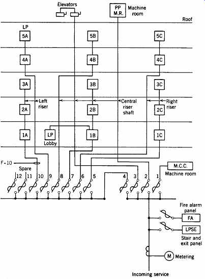
FIGR. 24 Typical power riser diagram. Ordinarily, the main switchboard would
be shown as a large rectangle with the feeders emanating from it, and a switchboard
schedule would detail the contents. Here, because of the unusual bus arrangement,
the main switchboard appears as it would on a single-line diagram.
TABLE 11 Current and Volt-Ampere Relationships Table 11 lists the relevant relations that will assist in computing currents. A note of caution is required regarding the use of computer programs to perform the previous calculations. It should be very clear that considerations of economy and anticipated expansion must be considered in designing a feeder system. Most software will not make such necessary comparisons and calculations unless specifically directed, and this frequently requires a multistage calculation. Most programs are arranged to select feeders on the basis of current loads, plus a specified spare capacity, without regard to expansion or economic considerations. It is important to under stand the methods used by any particular computer program in order to apply its output intelligently.
18. HARMONIC CURRENTS
A recent phenomenon, large harmonic currents, has been the cause of considerable difficulty in modern electrical installations. Without going into detail on this highly technical subject, a brief description of the problem and its causes is given here.
Conventional electrical loads such as lighting, resistive devices (heaters), motors, and the like are linear (i.e., the load impedance remains essentially constant, regardless of instantaneous voltage). This is not the case with most electronic equipment.
Computers, modems, printers, electronic lighting ballasts, variable-speed motor drives, and solid-state equipment of all types are essentially nonlinear loads. As such, they produce harmonic currents, of which the odd-order ones are additive in the power system neutral conductor. The most troublesome of these are the third harmonic and its odd multiples (9th, 15th, 21st, ...). These currents can become so large in a modern computerized office (especially with electronic ballasts) that instead of the neutral conductors carrying the unbalanced current in a 3-phase system (zero in a balanced system), they actually carry more current than the phase wires.
Other serious negative effects of harmonic currents are:
• Deterioration of electronic equipment performance; continuous or sporadic computer mal functions
• Overheating of the neutral-possibly causing neutral burnout and resulting in equipment being subjected to severe voltage variations
• Overheating and premature failure of transformers--even when the transformer nameplate rating seems adequate
• Overheating of motors because of operation with a distorted voltage waveform
• Nuisance tripping of circuit breakers and adjust able-speed drives
• Telephone interference
• Capacitor fuse blowing
The problem of destructive harmonic currents becomes progressively more severe as the amount of electronic equipment in use increases (as it does continuously).
Today, at least half of the electric load in a modern office-type facility is composed of nonlinear, harmonic-producing equipment. It follows that all such facilities, both existing and under design, must take necessary corrective measures. In the past, these measures consisted of oversizing equipment to avoid overload burnout; adding passive harmonic filters (which act to reduce harmonic content) in the electric distribution system; using isolation transformers at sensitive loads; selecting power sources with low output impedance to minimize voltage distortion; using controls that are relatively insensitive to harmonic distortion; adding meters throughout the system that measure true rms voltage and current rather than the average values shown by conventional meters; and other expensive (and essentially passive) power line conditioning. In view of the increasing severity of the problem, computer-controlled variable power-conditioning equipment (called active line conditioning) has become available. Such power conditioning equipment operates in a fashion similar to that described for active noise cancellation. The conditioner instantaneously and continuously analyzes the harmonic content of the line voltage and injects an equal but exactly out-of-phase voltage to cancel the harmonics and produce a pure sinusoidal voltage supply. The harmonic currents that are required by nonlinear loads are supplied by a digital signal generator. Other techniques are also used; their description is beyond the scope of this book.
In any retrofit work, the electrical designer must obtain a detailed electrical system analysis for the existing system, performed by engineers experienced in the field of power quality. Many existing systems carry as much as 70% to 80% harmonic current and constitute a major system failure waiting to happen. A proper power quality study, per formed with such instruments as true rms meters, harmonic analyzers, frequency selective voltmeters, and spectrum analyzers, will yield a true picture of an existing system and permit the electrical rehab work to be engineered with harmonic limitations as one of the important design parameters.
19. RISER DIAGRAMS
When all devices are circuited and panels are located and scheduled, a riser diagram can be pre pared. A typical diagram, shown, represents a block version of a single-line diagram except that, as the name implies, vertical relationships are shown. All panels, feeders, switches, switchboards, and major components are shown, up to, but not including, branch circuiting. This diagram is essentially a vertical section taken through a building electrical system.
EXAMPLE 3
Feeder F10 of FIGR. 24 serves lighting panels 1A, 2A, and 3A. Calculate the required feeder size, considering loads, future expansion, and voltage drop.
SOLUTION
The connected loads on these panels have been computed in accordance with the previous considerations and are:
LP-1A- 110 A LP-2A- 125 A LP-3A-100 A 335 A
These values include connected load, spares, and a 25% future capacity factor (the NEC requires that feeders be sized minimally for loads calculated by using the given NEC unit area loads plus any demand factors listed; see Article 220). If actual panel circuit loads are larger than the NEC minima, then they are the loads used in feeder calculations, and any reasonable demand may be used, provided that at no time do the totals drop below the minima specified in the NEC. Therefore, diversity factors may be applied between panel loads in a judicious manner.
In office building work, typical diversity factors are as follows:
Lighting Panels Fed from a Single Feeder Diversity Factor
1 or 2 1.00 3 or 4 1.09 5, 6, or 7 1.18 8, 9, or 10 1.33
Thus, the load on feeder F10, using 100% demand per panel and 1.09 diversity between panels, would be 335 × 1.0/1.09 = 307A.
Methods for handling future expansion were discussed previously. In this case, the feeder, before voltage drop considerations, would be 4-350 MCM THW in 3-in. C. In this case, the values in Table 10 can be mis leading if not read carefully. A 3-in. conduit will take a maximum of 400 kcmil THW. However, because the initial design is using only 350 kcmil, which also requires a 3-in. conduit, the expansion possible by rewiring with XHHW is ampacity of 500 kcmil, XHHW in 3-in. C ampacity of 350 kcmil, THW in 3-in. C = 430 A
310 A
= 1.39-i.e., 39% expansion
This should be sufficient.
The final consideration in sizing a feeder is volt age drop. The NEC suggests (does not require) that sizing branch circuit conductors for a maximum of 3% voltage drop to the farthest outlet, and sizing feeders so that the maximum combined feeder and branch circuit voltage drop to the farthest outlet does not exceed 5% will give reasonably efficient operation. These figures apply to all types of loads.
It is suggested that it makes economic sense to restrict branch circuit voltage drop to 2% to the farthest outlet while maintaining the overall 5% limitation. This allows a minimum 3% drop in feeders, which are frequently long and, because of size and ampacity inefficiency, relatively more expensive than small branch circuit wiring.
Many tables and curves are published by manufacturers from which voltage drop can be obtained.
Such a set of curves is shown in FIGR. 25, which shows the maximum length of run for a 1% drop.
Applying these curves to Example 3 and assuming an 80-ft (24-m) run gives the following.
From the curves, 307 A on 350 MCM cable gives a 1% drop in 50 ft (15 m). Therefore, the drop in 80 ft (24 m) will be 1.6%, which is well within our criteria, assuming that branch circuits were limited to a 2% voltage drop.
In summary, then, feeders are sized in accordance with load (actual or based upon unit area, whichever is larger) and voltage drop. Conduit may be oversized to address the potential for substantial future load expansion.
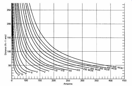
FIGR. 25 Curves for determining voltage drop in copper cables. Curves show
the maximum one-way circuit length for a 1% voltage drop.
20. SERVICE EQUIPMENT AND SWITCHBOARD DESIGN
The main switchboard shown in FIGR. 24 constitutes a combination of service equipment and feeder switchboard. The service equipment portion of the board comprises the metering and four main switches feeding the risers, motor control center (MCC), rooftop machine room, and elevators. The feeder board comprises switches 5 through 12.
Such an arrangement is permissible inasmuch as the NEC allows up to six fused switches or circuit breakers to serve as the service disconnect means.
This arrangement was chosen in order to separate to the largest extent possible the motor loads (elevators, air-conditioning equipment, basement power, etc.) from the lighting. Such a procedure minimizes lighting fluctuations resulting from motor starting and yields simpler maintenance. Also, the size of the main switch is reduced. This switchboard would be of the metal-clad dead-front type with switches or circuit breakers, as desired.
Other recommendations affecting service equipment are as follows:
• All equipment used for service, including cable, switches, meters, and so on, should be approved for that purpose.
• It is recommended that a minimum of 100-A, 3 wire, 120/240-V service be provided for all individual residences.
• No service switch smaller than 60 A, or circuit breaker frame smaller than 100 A, should be used.
• In multiple-occupancy buildings, tenants must have access to their own disconnect means.
• All building equipment should be connected on the load side of the service equipment, except that service fuses, metering, fire alarm and signal equipment, and equipment serving emergency systems may be connected ahead of the main disconnect (see FIGR. 24).
• For additional information on electric service, see NEC Article 230.
21. EMERGENCY SYSTEMS
(a) General Information
Some considerations relevant to power reliability are discussed in Section 1(b), and a brief review of the equipment available to supply emergency power is presented in Section 26.39. Emergency lighting equipment is covered in Section 16.31.
This section discusses possible emergency power supply arrangements. The choice of arrangement and the size and type of equipment depend largely upon the requirements of local codes, which deter mine the loads that must be supplied from the emergency system. Although this section uses the term emergency, the concepts involved are equally applicable to standby systems. Where differences occur, they are pointed out.
The three classes of electrical power supply systems that are included under the general category of emergency electric supply systems are:
• Emergency Systems: covered by NEC Article 700
• Legally Required Standby Systems: covered by NEC Article 701
• Optional Standby Systems: covered by NEC Article 702
The essential differences among the three classifications involve the purpose, application, and duration of the specific non-normal power supply.
All three types are activated when normal power fails, but only the first two types are legally required when so specified by a governmental agency having jurisdiction. Optional standby systems are, as their name states, optional; they are entirely dependent upon the project requirements established by the facility's owner or operator.
Emergency systems are those essential to human safety. As such, and depending upon the type of facility involved, they may supply power for fire detection, lighting, alarm and communication systems, elevators, fire pumps, and such loads as ventilation, refrigeration, and industrial processes where power interruption would imperil human safety. Generally, emergency systems must pick up the loads automatically within 10 seconds of power interruption. Where the emergency power supply consists of batteries, they must have a full load capacity of 90 minutes. Where the power supply is an engine-generator set, an on-site fuel supply that will suffice for a minimum of 2 hours of full load is required. The entire wiring system for an emergency power system must be separate and distinct from the normal power system, except where both systems are connected to the same item of equipment.
Legally required standby systems are those required to provide power for essentially the same types of loads as emergency systems, except that their absence does not involve immediate danger to human life. Systems for firefighting, control of health hazards, long-term rescue operations, and industrial hazard prevention would be among the electrical loads served. For these systems, loads must be picked up automatically within 60 seconds of failure of normal power and be maintained for the same mini mum periods of time specified for emergency power systems. Wiring may be run in the same enclosures as those used for the normal power system.
Optional standby power systems are intended essentially to minimize economic loss, and there fore can supply any load identified by the building owner. Connection of the selected standby source can be manual or automatic, and the duration of service is entirely at the owner's discretion. No restrictions are placed on the wiring system beyond those applied to the normal electrical wiring system.
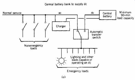
FIGR. 26 Use of a central battery for emergency power supply. When all loads
can be energized with dc, the arrangement of (a) is satisfactory. When ac as
well as dc must be distributed, a central inverter is added, as in (b), and
the ac and dc emergency loads are fed separately.
(b) NFPA Codes
The NEC does not determine whether an emergency system is required; that decision is made by the applicable jurisdictional authorities and is generally a response to the requirements of NFPA 101. Once a determination to provide an emergency system has been made, however, the equipment and installation must comply with the requirements of the NEC. Relevant NFPA codes (updated on a regular basis) include:
NFPA 70 National Electrical Code NFPA 99 Standard for Health Care Facilities NFPA 101 Life Safety Code NFPA 110 Standard for Emergency and Standby Power Systems NFPA 111 Standard on Stored Electrical Energy Emergency and Standby Power Systems
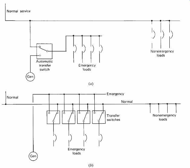
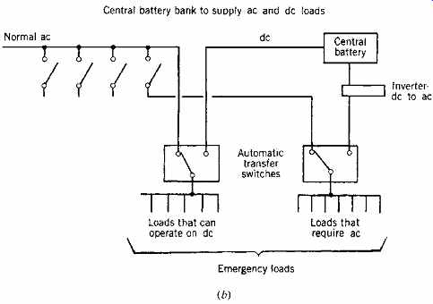
FIGR. 27 Alternative arrangements of emergency/normal power feed. In (a) a
single transfer switch serves the normal power and transfers to the generator
upon power failure. In (b) there are multiple smaller transfer switches, thus
reducing the chance of a single equipment failure faulting out the entire emergency
power system.
(c) Technical Considerations
In general, when emergency power is discussed, it is assumed to be replacing normal power; that is, the assumption underlying most codes and standards is that power must be supplied to selected loads within the building because of a utility power outage. In good-practice design, cognizance must also be taken of situations in which normal power has not failed, and an outage is localized because of an in-building equipment failure. This aspect of design-reliability-is left to the designer and owner to decide in the context of a given building situation. Some of the arrangements discussed here differentiate between the nature of outages-that is, a utility or general outage versus an equipment or local outage.
An exception to this generalization occurs with health-care facilities, where NEC (in Article 517) specifies an internal electrical design that largely covers both types of outages down to the distribution level. Refer to the referenced NEC article for further information.
An emergency system includes all devices, wiring, raceways, and other electrical equipment, including the emergency source that is intended to supply electric power to the selected load(s). An important aspect of code requirements permits the use of a single power source for (1) emergency, (2) legally required standby, and (3) optional standby systems, provided that it is equipped with automatic selective load pickup and load-shed ding equipment that will ensure adequate power to the three types of systems in the order of priority stated (1, 2, 3).
1. Where emergency loads are not substantial, a storage battery arranged to be connected automatically on power outage may be used.
Where all emergency loads can be operated on dc, the arrangement of FIGR. 26a is used.
(Note that ac lighting can accept dc emergency power if equipped with a local inverter, as discussed in Section 16.31.) If ac power is required, the arrangement of FIGR. 26b can be utilized.
2. Where emergency loads are larger than can be practically supplied by a battery installation, and where a start-up and power transfer time of up to 10 seconds is tolerable, a generator set is employed. A combination of emergency sources may be used in a single building. For instance, a generator can supply bulk power loads and a battery installation selected lighting loads.
The system can be arranged with a single transfer switch that senses normal power loss, as in FIGR. 27a, or it can use multiple switches, each one of which will sense power loss at its downstream location, as in FIGR. 27b. The latter system pro vides greater power reliability, provided that the design is such that the emergency power uses an independent power path to the transfer switches.
Otherwise, a fault in a junction box or an item of equipment that interrupts normal power down stream will also prevent emergency power from reaching that point.
3. Some codes permit the use of two separate electric services in lieu of a normal service plus an emergency source, provided that the two sources are truly independent-that is, come from different utility transformers or feeders; enter the building at different points and, preferably, from different directions; and use separate service drops or laterals. The point is that the type of reliability desired can be obtained only by minimizing the possibility of a single event interrupting both services. The usual arrangement is for one such utility service to be normal and the other standby.
4. The least reliable arrangement is one in which the emergency loads are connected ahead of the main disconnects and are so arranged that a downstream fault within the building will not affect these items. This situation is illustrated in the riser diagram of FIGR. 24, where the stair and exit panel (which supplies egress lighting) and the fire alarm panel are connected ahead of the building main disconnect and protected with their own fuses. This arrangement is permitted only for Legally Required Standby Systems (NEC Article 701) and not for Emergency Systems as defined in NEC Article 700. The items that may be connected ahead of the main service equipment are generally limited to emergency lighting, fire alarm, fire pumps, standby power equipment, and other alarm and protective equipment, each of which must be provided with a separate disconnect means and overcurrent protection (see NEC Article 230-82).
This power arrangement can do nothing in the event of a power outage. It was once very common, but is now falling into disuse as a result of more stringent codes and its serious shortcomings.
5. The NEC recognizes a category of equipment for emergency illumination called unit equipment. These types of devices, discussed and illustrated in Section 16.31(d), consist of individual self-contained packages with a battery, charger, and light source permanently mounted and wired at required locations. The panel device feeding these units should be clearly identified.
References and Resources
Numerous standards from the NFPA dealing with emergency power systems are identified in Section 21b.
McGuinness, W. J., B. Stein, and J. S. Reynolds. 1980. Mechanical and Electrical Equipment for Buildings, 6th ed. John Wiley & Sons. New York.
Stein, B. 1997. Building Technology, Mechanical and Electrical Systems, 2nd ed. John Wiley & Sons. New York.