AMAZON multi-meters discounts AMAZON oscilloscope discounts
1. A CONTEXT FOR PHOTOVOLTAICS
A PHOTOVOLTAIC (PV) SYSTEM PRODUCES electricity through direct conversion of incident solar radiation (primarily radiation in the visible spectrum-light). This is an incredibly useful trans formation process. Virtually every building of any size or function requires and consumes electricity.
Solar radiation is a renewable resource, which will generally impinge upon a building in useful quantities in most climate zones (whether or not the building uses it for beneficial purposes). PV then seems an ideal design solution-providing a needed energy form from an otherwise often unused resource. In an ideal world, every building would have a PV system. Unfortunately, the economics of PV power production dampen this idyllic picture.
PV power production generally costs an owner more than utility-provided power, even considering reasonable life-cycle costing scenarios. In fact, the economics are currently such that PV systems for buildings are the exception rather than the rule.
There has long been hope that the economic picture would change through the evolving availability of much cheaper PV components. This has not really happened. Thus, any future shift in economics will likely occur mainly as the result of higher cost for competing electricity sources (utilities) and/or rebates or incentives from governments or utilities for distributed, greener power sources.
PV electric power systems, which until the middle to late 1980s were little more than a curiosity in the United States because of their very limited applicability and discouraging economics, have recently begun to make a noticeable impact on the commercial electrical power scene. This has come about for several reasons, the most important of which are federal government-financed research and development, and state and federal government-sponsored legislation in the electric utility field. The PV Manufacturing Technology project (PVMaT) involving the U.S. Department of Energy (DOE) and 20 private companies (launched in 1990), plus the 1992 Building Opportunities in the United States for Photovoltaics (PV:BONUS) program (also sponsored by the DOE) resulted in the reduction of PV module costs from upwards of $5.00 per watt to about $1.50 to 2.50. In addition, these initiatives spurred the development of new PV module materials, construction techniques, and product forms; increases in PV module efficiency; and a sharp overall decrease in the cost of power produced from about $0.50 to $1.00 per watt to about half that amount, depending upon the system configuration. The legislative impetus has taken the form of utility deregulation and specific legislation requiring utilities to purchase power produced by small, private installations.
Several recent government efforts to foster the development of PV systems are under way. The ( U.S.) Photovoltaic Industry Roadmap is an industry-led effort to help guide domestic PV research, technology, manufacturing, applications, markets, and policy. The Roadmap presents the intended direction of the PV industry, its critical partners, and U.S. government programs for the years 2000 to 2020. The U.S. PV program is associated with the International Energy Agency's (IEA) Task 16 effort focused upon PV systems for buildings. The potential market for building-integrated PV systems in the United States is enormous, and many companies are beginning to work at the development and commercialization of building-integrated PV components and systems. Increasing and substantial U.S. sales of PV roof shingles are indicative of this potential. Green building design efforts are also increasing interest in PV systems, with LEED new construction credit provided for renewable energy resources and for green power.
The 1978 federal Public Utilities Regulatory Policy Act (PURPA) required electric utilities to buy electric power at a price equal to the costs they avoid by not having to produce that power. The utilities generally interpret that "avoided cost" as fuel cost only, without considering other avoided costs such as additional plant construction. As a result, energy is often bought under this law at about $0.03/kWh by the same utilities that sell energy at $0.08 to 0.15/kWh. This spread obviously does not encourage the construction of grid connected PV installations (see Section 29.5b). Subsequently, many states adopted net-metering laws that reduced this price unbalance. In this arrangement, the utility buys power during peak PV generation periods (see FIGR. 1) at the same rate at which it sells power. At the end of a billing period (usually 1 month), any imbalance between utility-purchased and customer-purchased power is paid for at the given rates (i.e., if the customer used more power than he/she generated, that power is paid for at the conventional utility rate). Conversely (and less commonly), if the customer generated more power than was used, the utility would buy it at the avoided-cost rate.
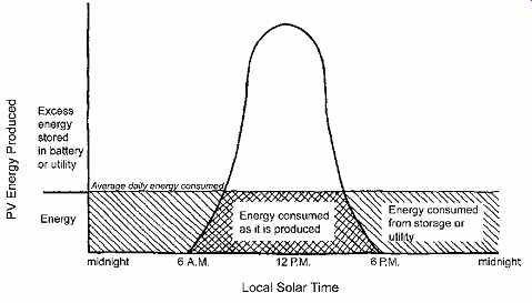
FIGR. 1 Graph representing electricity produced and used by a residence equipped
with a PV array. Daily energy use is shown as a uniform average over a 24-hour
period to indicate overall quantity but not an actual usage pattern. The bell-shaped
PV energy production curve is centered on solar noon and extends from sunrise
(solar 6:00 A.M.) to sunset (solar 6:00 P.M.). The area of the bell curve above
the average consumption line indicates electricity that would be purchased
by a utility in a grid-connected system or stored in batteries in a stand-alone
system. (From Harris, Miller, and Thomas. 1985. Solar Energy Systems Design,
p. 715. Reprinted with permission of John Wiley & Sons, Publishers. Redrawn
by Amanda Clegg.)
The net-metering arrangement is attractive economically to both utility and user. A utility buys power that offsets its peak afternoon load, which is particularly severe in warm weather, and sells power in its off-peak morning and evening periods. A residential customer sells power at the PV installation's peak output, which is also usually a period of low user consumption (FIGR. 1), and buys it back at the same price in the evening, when PV output is low but power demand is high. The arrangement removes the necessity for an expensive battery installation that, in a stand-alone system, provides power during periods of low PV energy production. This advantage, combined with other advantages such as having a nonpolluting power source, has led to a large increase in grid-connected installations. Indeed, the attractiveness of having a green, environmentally beneficial electric power supply is so great that a number of electric utilities have instituted a (primarily residential) PV installation program in which the utility installs and maintains a PV system on the customer's premises (usually on the roof), for which the customer pays a nominal surcharge on the monthly electric power bill. The advantages of net billing, however, are available only to customers who initiate and maintain a PV system themselves.
2. TERMINOLOGY AND DEFINITIONS
A generally accepted terminology has developed in the PV field. The list that follows contains common terms and their accepted definitions. Particular attention should be paid to two terms that are often incorrectly used interchangeably: insolation and irradiance. Irradiance is the amount of solar power impinging on a specific area, usually measured in units of watts per square meter-and represents an instantaneous value. Insolation is the amount of solar energy received by a given area, measured in Wh/m^2, kWh/m^2, Btu/ft^2, or MJ/m^2 (with 1 kWh/m^2 = 317.2 Btu/ft^2)-and represents a time-averaged value.
Avoided cost. The minimum amount an electric utility is required to pay an independent power producer under the Public Utilities Regulatory Policy Act of 1978.
Balance of system (BOS). All components other than the PV modules themselves, which include the system electronics, support structure, and storage.
BIPV. Building-integrated photovoltaic (system); a PV system with cells/modules incorporated as an integral part of the building envelope (rather than simply tacked on to the building shell).
Blocking diode. A diode used to block reverse flow of current into a PV source circuit.
Interactive system. A PV system that operates in parallel with the electric utility lines and may be designed to deliver power to the utility.
Inverter. Commonly known as a power con version system (PCS), an inverter is a device that changes direct current (dc) to alternating current (ac). An inverter is not the same as a power-conditioning unit (PCU).
Panel. A collection of modules mechanically fastened together, wired, and designed to pro vide a field-installable unit.
Peak sun hours. The number of hours per day at an irradiance of 1 kW/m2 that is equivalent to the total daily insolation energy.
PV array. A mechanically integrated assembly of modules or panels with a support structure and other components, as required, including tracking apparatus where used, forming a power-producing unit.
PV cell. The basic PV device that generates electricity when exposed to solar radiation.
PV module. The smallest complete, environ mentally protected assembly of PV cells and other components normally sold by a manufacturer; comprising several (or many) PV cells.
PV system. All the components and subsystems that, in combination, convert solar energy into electrical energy suitable for connection to a load.
Stand-alone system. A PV system that sup plies electrical energy without interconnection to any other power source.
Thick-crystal photovoltaics. The most common commercial type of PV material.
Thin-film photovoltaics. PV devices made of a semiconductor material, such as copper indium diselenide or amorphous silicon, a few micrometers thick, deposited on substrates of glass, ceramic, or another compatible material.
3. PV CELLS
The production of an electric charge when solar radiation (primarily light) strikes some metallic surfaces has been a recognized physical phenomenon since the mid-nineteenth century. Around 1905, Einstein established a mathematical basis for what has come to be known as the photoelectric effect. The explanation of this effect, in simplified and qualitative terms, is approximately as follows. Light exhibits both wave characteristics and characteristics of a stream of energetic particles called photons. When a photon strikes a photoelectric metal surface, it dislodges a single electron from its normal orbit, causing a charge to appear. When pure silicon is exposed to an intense stream of photons, as from sunlight, a large number of electrons are dislodged from their orbits and proceed to wander about the crystal lattice structure of the silicon crystals. By a process called doping, impurities are deliberately added to pure silicon to create a P-N (positive-negative) junction, across which the electrons flow to create an electric current and give the doped silicon the properties of a semiconductor. If the semiconducting doped silicon is exposed to light and the negative and positive sides of the junction are connected through a load, an electron flow (a current) commences from the negative side of the junction to the positive side, doing work on the load. Work, of course, is energy. The energy comes from the fast moving photons (light) and is imparted to the dislodged electrons by impact. The overall effect is to create a current flow proportional to the intensity of photon bombardment-that is, proportional to light intensity. Figure 29.2 is a schematic representation of this process.
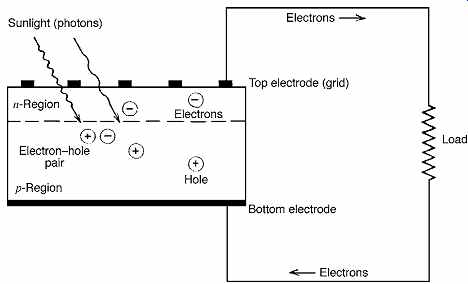
FIGR. 2 Schematic drawing showing the conversion of solar energy to electrical
energy by a PV cell. Photons from solar radiation dislodge electrons in the
silicon semiconductor surface, creating a positively charged "hole." The
N-P junction creates an electric field that "sweeps" electrons across
the junction. When the top and bottom electrodes are electrically connected
through a load, an electric current flows. This current is capable of doing
work (supplying energy). (From Meyers, ed. 1983. Handbook of Energy Technologies.
Wiley-Interscience. Reprinted with permission.)
The photons in solar radiation are not uniformly energetic. It has been found experimentally that a photon must have an energy of at least 1.08 electron-volts (corresponding to a wavelength of 1150 nm) to dislodge an electron. Photons at longer wavelengths do not have sufficient energy to create the photoelectric effect. Because shorter-wavelength photons are more energetic, the entire visible spectrum (light) is useful in PV action, the magnitude of current produced depending upon the intensity of light. According to Einstein's PV theory, a single photon can only dislodge a single electron; thus, any photon energy in excess of the minimum (dislodgement) level is dissipated as heat. For this reason, PV cells generate heat as well as electricity, and some means of heat collection or dissipation is required in practical PV array construction. Commercial PV cells operate at an overall insolation-to-electric energy conversion efficiency of around 8% to 12%. By layering different strata of semiconductor material, each of which is sensitive to a different limited frequency bandwidth (called bandgap), efficiencies as high as 35% to 40% can be achieved. Economic considerations, however, have limited today's commercial PV modules to a maximum of two layers with a maximum conversion efficiency of about 12%.
As mentioned previously, intensive research and development work on solar cell construction has yielded a new generation of PV materials that are variously referred to as thin-film technology and polycrystalline technology, using various copper and cadmium compounds and amorphous rather than large crystal silicon modules. These materials offer higher efficiencies, can be manufactured into large elements, and, because they do not require a glass cover, can be integrated into standard building material formats (as building-integrated PV elements). Typical data for two commercial products using this newer technology are:
Amorphous Silicon Module
Dimensions: 2 ft × 4 ft × 2 in. (610 mm × 1220 mm × 50 mm)
Weight: 33 lb (15 kg)
Electrical: 50 W, 72 V, 0.7A
Thin-Film Polycrystalline Module
Dimensions: 2 ft × 4 ft × 2 in. (610 mm × 1220 mm × 50 mm)
Weight: 22 lb (10 kg)
Electrical: 75 W, 17 V, 4.5A
These second-generation PV materials have high efficiency and a flexible physical format, distinct advantages over the older, large crystal silicon wafer elements. However, the latter are cheaper, extremely hardy, reliable, and long-lived, as has been demonstrated in many satellite and space vehicle applications. The newer units are initially somewhat unstable and have a shorter life than the large crystal silicon units.
The PV cell is the smallest electricity-producing unit in a PV system. Cells are not sold individually as commercial products but are arranged by the manufacturer into modules. A module is the smallest commercially available electricity-producing increment. The size of a module and the number of modules required to produce a desired electrical output depend upon the type of PV cell used, the manufacturer's product line, and the intent of the PV system designer. If more than one module is required, as is often the case, multiple modules are assembled on site into arrays. A module is a self-contained product; an array is a field-assembled group of modules.
4. PV ARRAYS
A PV array is a complete and connected set of modules mounted and ready to deliver electricity. Two basic array arrangements exist: stationary and tracking. Building-mounted arrays are typically stationary and often have the advantage of not requiring a substantial support structure, although even a simple roof mounting on a pitched roof can be expensive due to the labor cost involved. The materials usually used for ground-mounted array structures are concrete, galvanized steel, and aluminum. Wood and painted iron are not recommended because of their high maintenance costs and relatively short life. The design of an array mounting will depend upon the array size, weight, mounting angle, and wind loads and is therefore unique to each installation. Mounting on a wooden pole or steel pipe with a single support point is limited to relatively small arrays in low-wind areas because of the stress on the support arrangement. Several typical fixed mounting arrangements are shown in Figs. 3 through 5.
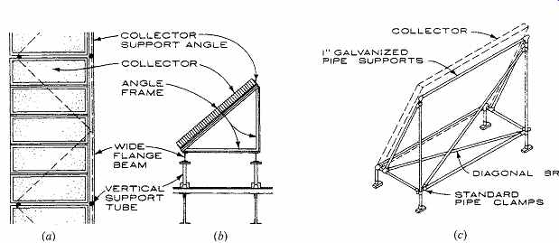
FIGR. 3 Typical mounting techniques for PV arrays. (a) Plan of the arrangement
for mounting large arrays on a horizontal surface. (b) Section through (a)
showing mounting and arrays. (c) Simple pipe rack mounting for a small array.
For all installations, ensure that wind and seismic loads, snow collection,
and array cooling have been considered. (Diagrams reprinted with permission
from Architectural Graphic Standards, 10th ed. 2000. John Wiley & Sons,
Publishers.)
The angle, measured from the horizontal, at which a flat-plate collector is mounted is known as the tilt angle. For a stationary (non-tracking) array, total annual insolation is maximum for a tilt angle
equal to the latitude of the site. To maximize winter insolation, when the sun is lowest, the tilt angle can be increased to latitude plus 15º. Conversely, to maximize summer insolation, when the sun is highest, the tilt angle can be reduced to latitude minus 15º. The tilt angle chosen for a stationary array depends upon PV output usage schedules, the amount of insolation for the months of the year, and economic considerations.
Tracking arrays follow the motion of the sun and thereby substantially increase the insolation per unit area of solar cells. Single-axis tracking follows the sun's motion from east to west while maintaining a constant array tilt angle. This type of tracking can increase insolation by 35% to 50% throughout the year and is most effective at low latitudes. Completely passive, sealed Freon, single-axis tracking drives are available for small to medium sized pole-mounted arrays in low-wind areas.
Where wind velocity is high, a motorized drive using PV-generated power may be necessary. Dual-axis tracking (following solar altitude and azimuth) for flat-plate collectors and altitude tracking for various designs of concentrating collectors are beyond the scope of this book.
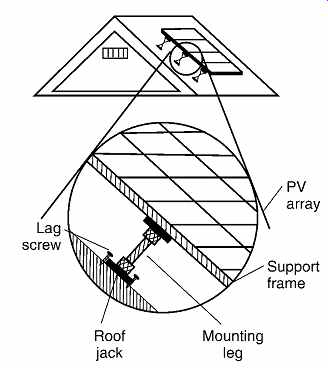
FIGR. 4 Typical roof mount for a PV array. Array tilt and azimuth can be adjusted
through the mount design. Exercise caution in snow areas so that accumulating
snow does not block the array and does not slide off onto pedestrians. (From
Stand-Alone Photovoltaic Systems. Sandia Laboratories. 1995.)

FIGR. 5 Flat-plate PV collector support structures. (a) Wooden-pole torsion
tube support. (b) Concrete truss support. (From Meyers, ed. 1983. Handbook
of Energy Technologies. Wiley-Interscience. Reprinted with permission.)
5. PV SYSTEM TYPES AND APPLICATIONS
There are two basic types of PV systems: stand-alone and grid-connected. These names well describe their essential characteristic, which is their relationship to an external source of electricity such as a utility connection.
(a) Stand-Alone Systems
A stand-alone system is just that; it is isolated from any outside electrical connections and is designed to do a carefully defined specific job. Stand-alone systems are the oldest PV installations because they were essentially the only solution to the problem of electrifying a remote and/or unattended load.
Stand-alone installations typically supply electricity for sign lighting, railroad crossing lights, unattended pumps, lighthouses, unattended navigational aids, microwave repeaters, motor homes, sailboats and yachts, isolated small residences, and the like. The common characteristic of all these installations is the impossibility or impracticality of feeding them from a utility grid. When loads become larger than can be supplied by a practical solar array (from a physical or economic viewpoint), and particularly when the peak load is periodic rather than continuous, a fuel-powered generator is usually added to the system. Such a system is known as a hybrid stand-alone system and is used frequently for remote residences where the connection charge levied by the local utility is so large that a PV system is an economical and environmentally friendly solution to the problem of providing electricity. Schematic diagrams of stand-alone system types are shown in Figs. 6, 7, and 8.
The difference between the systems shown in Figs. 6 and 7 is the use of an energy storage medium-in most cases, a battery. The direct connected system in FIGR. 6 is applicable only with loads that tolerate variable power levels ranging from zero at night to maximum at solar noon. The most common of these is water pumping, using a dc motor to drive a positive displacement (piston) pump. Such installations are frequently used to fill elevated water tanks because a slow, interruptible fill rate does not adversely affect the water system's usability.
The vast majority of stand-alone systems are assembled as shown in FIGR. 7, using a storage battery to store excess energy produced during peak insolation hours for use during periods of reduced solar resource (cloudy days) and full darkness (nighttime). With proper component selection, as is discussed in detail in subsequent sections, stand alone PV systems can be used to adequately supply remote year-round residences, small mercantile establishments, and other off-grid loads.
A stand-alone system may contain a dc-to-ac inverter if any of the loads require ac that can not be supplied by a built-in inverter. The choice of whether to use a single central inverter or distributed smaller inverters is largely an economic decision. Fluorescent lamps, a reasonably efficient source of light, are available with integral inverter ballasts. Some kitchen appliances and power tools, however, are not readily available in a dc or battery-powered format, although that situation is rapidly changing and warrants careful investigation during system design.
The hybrid stand-alone system shown in FIGR. 8 is similar to the stand-alone system in FIGR. 7, with the addition of a small ac generator.
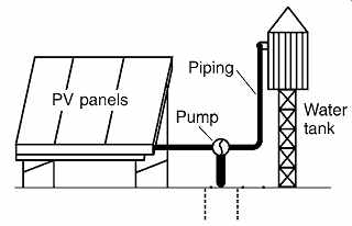
FIGR. 6 Typical direct-connected PV installation feeds electric power to a
positive-displacement pump that pumps water into an elevated tank.
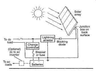
FIGR. 7 Schematic diagram of the most common type of stand-alone PV installation.
The blocking diode prevents reverse current flow when the battery voltage exceeds
that of the PV array. The charge controller prevents overcharging of the battery
and excessive current drain. If ac loads are present, a dc-to-ac inverter is
added, sized as required. (From Harris, Miller, and Thomas. 1985. Solar Energy
Systems Design. Reprinted with permission of John Wiley & Sons, Publishers.)
This type of system, as noted previously, is used where operation of a heavy ac load, such as a clothes washer or another relatively large ac motor-driven appliance, is necessary. Where these loads are fairly continuous, as with refrigeration and air-conditioning equipment, a larger PV system should be considered. A continuously running engine-generator set is a source of noise and air pollution, and the ongoing consumption of a fossil fuel resource in such an installation makes it contradictory in spirit to a completely silent, pollution-free, renewable resource driven, solar-powered PV installation.
(b) Grid-Connected Systems
Prior to the advent of net-metering, the number of stand-alone PV systems in areas served by electric utility grids was small because of the overwhelming economic advantage of purchased power. Even today, with net-metering, the payback period upon an initial PV system investment seldom justifies an installation on purely economic grounds, although the continuous development work in PV materials may change that situation.
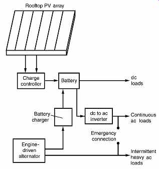
FIGR. 8 One arrangement for a hybrid stand-alone PV system (control and safety
devices are omitted for clarity). A diesel-, gasoline-, or propane-driven ac
generator (alternator) supplies large, intermittent ac-only loads, whereas
the PV array and battery supply dc loads and continuous ac loads through an
inverter.
During long, cloudy periods the alternator can charge the battery and, via an emergency connection, can also supply the regular ac loads. Other arrangements are possible, such as using a larger inverter to supply an all-ac system, with the alternator supplying intermittent heavy ac loads and all loads during low-battery periods.
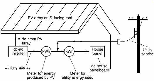
FIGR. 9 Schematic drawing of a grid-connected PV system arranged for net-metering.
Power from the array is converted from dc to utility-grade ac power (constant
voltage and frequency; low harmonic content) by the inverter and fed to the
utility connection through a kWh meter that measures the electricity sold to
the utility. The second (utility company) meter measures the total power used
by the structure. The difference in meter readings represents the positive
or negative (credit) utility billing.
In a stand-alone arrangement, battery costs over the life of the system can exceed those of the PV array. Lead-acid batteries are relatively cheap but have a short life; nickel-cadmium batteries have a longer life but are much more expensive. By replacing the batteries that furnish energy storage and carryover in a stand-alone system with a utility connection that effectively serves the same purposes, and by taking advantage of the economies available from building-integrated PV elements (see Section 5c) in new construction, an economical PV system with reasonable payback can be constructed. A schematic diagram of one such system arrangement is shown in FIGR. 9.
The inverter shown in the diagram creates utility-grade ac from the PV array dc output and feeds it to the utility through an electric (kWh) meter. The inverter shown is equipped with a safety cutoff that instantly disconnects the PV system from the grid if a utility outage is sensed. This is a requirement of the electric utilities to ensure that their maintenance personnel are not endangered by PV electric power being fed into an apparently deenergized line.
The power company supplies house power through a second meter, as shown. In net-metering, the difference between the readings of the two meters is either billed to the consumer at the normal utility rate or credited to the consumer at the avoided-cost rate, depending on which meter reads higher. A consumer will notice no difference what ever in electric service, except in the lower, or possibly even negative, electric utility bills.
More recently, to encourage wider use of non polluting PV power, some utilities have permitted the installation of small, individual PV modules in existing buildings. These units plug into convenience outlets in the building, supplying power to the building itself. Any excess electrical energy not required by the structure is fed back into the utility via their reversible energy meter. This arrangement is shown schematically in FIGR. 10. Each PV module (panel) is equipped with a built-in, high-quality inverter that produces utility-grade power and is equipped with the safety devices described previously. A common commercially available unit of this type is rated at 100 W peak, 85 W nominal, 120 V, 60 Hz, measures approximately 2 ft × 4 ft × 4 in. (610 mm × 1220 mm × 50 mm), and weighs 25 lb (11 kg). The advantage gained with these units is that a user can begin with one or two modules and then expand as desired, without a relatively high first cost investment and without a centralized installation requiring professional construction and electrical personnel. Some power companies require separate disconnect switches for each PV unit rather than relying only on physical disconnection of the unit plug from the wall outlet.
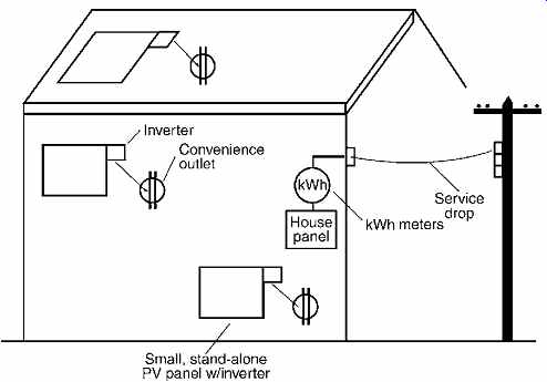
FIGR. 10 Schematic drawing of a grid-connected PV system using small, distributed
PV arrays connected to the house distribution system via convenience outlets.
In this arrangement, the utility meter is unratcheted (reversible) so that
excess PV-produced electricity reverses the power company's meter. Any net
monthly credit is calculated at the avoided-cost rate.
(c) Economic Considerations
Economic issues can be complex, and they are often the deciding factor in the choice between full PV, a PV-grid combination, and a conventional (grid) electric service. Among the cost factors are:
• Cost of a grid connection.
• Cost of power from the grid.
• Life-cycle cost of each component of the system over the life of the entire installation.
This is necessary because the life span of individual components varies sharply; PV modules last about 20 years, batteries about 5 years, electrical components 10 to 20 years (or more), PV module mountings 15 to 25 years, tracking mechanisms (if used) 5 to 10 years, and so on.
• Life-cycle maintenance costs (parts and labor) for each item.
• Financing costs.
• Cost credits for PV systems, including such items as use of a system battery as an uninterruptable power supply (UPS) source for computers and peripherals, savings from avoided grid-power service interruptions, and construction cost credits when PV modules are used in lieu of building elements.
The last factor has taken on considerable importance in recent years with the development of building-integrated PV (BIPV) elements. A traditional PV installation consists of PV modules mounted near or on a building or facility. Often, the modules are roof-mounted if a roof surface of appropriate orientation (generally south-facing) and sufficient size is available. The development of thin-film amorphous silicon modules permits incorporation of PV cells into assemblies that can replace traditional building construction elements (typically in the form of roof panels, roofing tiles, wall panels, or skylights). These assemblies fulfill the dual function of producing electricity and weatherproofing the building envelope. In the jargon of design intent, they are transformer elements, replacing historically used barrier or filter elements. In such cases, only the difference in cost between standard construction and BIPV construction should be taken as an additional cost of the PV system.