AMAZON multi-meters discounts AMAZON oscilloscope discounts
THE MAJOR COMPONENTS OF A BUILDING electrical system can be grouped into three major categories: wiring and raceways, power-handling equipment, and utilization equipment. The first category includes conductors and raceways of all types; the second includes transformers, switch boards, panelboards, large switches, and circuit breakers; and the last includes utilization equipment such as lighting, motors, controls, and wiring devices. After an introduction applicable to all electrical materials, this section discusses in detail the items in the first of these three categories-that is, the wiring and raceway system. Section 26 covers most of the items in the other two categories, with the exception of lighting equipment, which is discussed in Part III. Signal systems, building control, and automation are discussed in Section 30.
1. SYSTEM COMPONENTS
Figure 1 illustrates that power distribution equipment proceeds from the service point to the utilization points in a progression of decreasing circuit capacity. This is analogous to the arrangement of water supply systems and HVAC systems; the distribution equipment is largest at the supply point, and decreases in size on its way to the farthest utilization points. The reverse is true in collection systems such as those for drainage and venting; in collection systems, piping is smallest at the initial collection points, growing larger (in steps) as the quantities of fluid increase.
A typical single-line diagram does not differentiate by line weight between heavy and light (large and small) conductors (the heavier the conductor, the greater the amount of power being carried), but the single-line diagram of FIGR. 1 does differentiate in order to show relative power levels throughout the system. This "size" differentiation is more clearly shown in FIGR. 2, which is a pictorial representation of a system similar to that of FIGR. 1-but in somewhat greater detail and omitting items beyond the panelboard. Only standard items are shown; special items, however common, such as emergency and uninterruptible power sources, energy controls, service transformers, and the like, are omitted for the sake of clarity.
2. NATIONAL ELECTRICAL CODE (NEC)
The National Electrical Code (NEC) of the National Fire Protection Association (NFPA) defines the fundamental safety measures that must be followed in the selection, construction, and installation of electrical equipment and systems. This code is used by all inspectors, electrical designers, engineers, contractors, and operating personnel. Having been incorporated into the Occupational Safety and Health Act of 1970 (OSHA-which is also the acronym for the Occupational Safety and Health Administration, which administers the Act) it has, in effect, the force of law throughout the U.S. Frequent references are made to the NEC throughout this section.
In addition to the NEC, many large cities such as New York, Boston, and Washington, D.C., have their own electrical codes that, although similar to the NEC, contain numerous special requirements.
In order to ensure a minimum standard of intrinsic electrical safety for electrical equipment, a single organization was needed to establish standards and to test and inspect electrical equipment.
Underwriters Laboratories (UL) is such an organization, and it publishes extensive lists of inspected and approved electrical equipment. These listings are universally accepted, and many local codes state that only electrical materials bearing the UL label (of approval) are acceptable.
3. ECONOMIC AND ENVIRONMENTAL CONSIDERATIONS
The selection of electrical materials involves not only choosing a material or assembly that is functionally adequate and, where necessary, visually acceptable, but also the consideration of costs.
Usually many types of equipment (from a range of manufacturers) will fulfill the technical requirements of a project. In most cases, final selection of a device or approach hinges upon cost. Ideally, "cost" would be life-cycle cost; more realistically it is often first cost.
The selection decision is relatively simple when various options differ only slightly from each other and a straightforward first-cost comparison is all that is required. Often, however, the choice is not so simple, because materials and equipment may vary considerably in characteristics other than functional suitability, demanding a more detailed cost study.
Such economic analyses are frequently performed to make comparisons among competing HVAC systems. This happens less often when dealing with electrical systems because, from an energy point of view, electrical systems are generally less critical (relative to consumption) than HVAC systems, and it is energy costs that are often the decisive factor in economic analyses. Life-cycle system/equipment costs (over the life of the structure) are expressed in present-value dollars, or annual owning and operating costs, including equipment amortization costs.
The type of analysis used will depend upon the situation. Such comparisons are useful, however, only when both the initial cost and the operating costs will be borne by the same individual-that is, an owner-operator. In the case of a speculative building venture, first cost is usually the deciding factor for a developer because others will bear the operating costs.
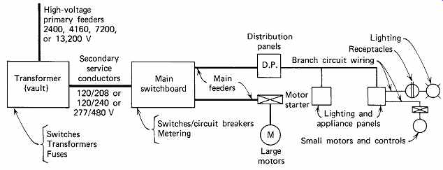
FIGR. 1 Single-line diagram of a typical building electrical distribution
system, from the incoming service to the utilization items at the end of the
system. This is also referred to as a block diagram because the major components
are shown as rectangles, or blocks. When this same type of information is presented
showing the vertical spatial relationship between components, it is called
a riser diagram; when electrical symbols are used in lieu of the blocks, it
is called a one-line or single-line diagram. The connecting conductors between
the major system components are drawn here with varying thickness to reflect
size, and thereby power-handling capacity. In normal practice, all connecting
lines are shown the same weight. Also, branch circuits are not usually shown;
the typical diagram ends at the lighting and appliance panels.
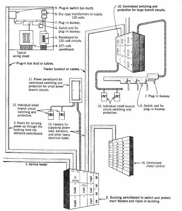
FIGR. 2 Diagrammatic (pictorial) representation of a typical building electrical
power system with relative power capacity indicated by the size of the conductors.
This diagram does not extend beyond the local panelboard and includes only
commonly used items. Note also that the entire wiring system is, in effect,
jacketed in steel. (Courtesy of General Electric.)
It is often difficult to perform a life-cycle cost analysis because accurate data regarding service life and maintenance costs for electrical equipment may not be readily available. Still, even if a precise analysis cannot be done, the principle involved in life-cycle analysis should be considered in the selection of all electrical materials and equipment, bearing in mind the relative importance to an environmentally responsive building of energy-utilizing and -conveying equipment. See Appendix I for an explanation of cost analysis techniques. Economic issues for particular items are found in the following technical discussions.
Energy costs are a major factor in economic analysis. Energy considerations, however, are at least as important in and of themselves because of ever increasing concerns about limited energy and natural resources. This concern is addressed in the context of building energy budgets and their components, including lighting, elevators, and electric motors that are a part of many building systems. Building codes in the U.S. only lightly deal with electrical energy system efficiency-primarily through the requirements presented in ASHRAE Standard 90.1. No explicit recommendation regarding electrical system design is provided in any of the current green building guidelines.
4. ELECTRICAL EQUIPMENT RATINGS
All electrical equipment must be rated for the normal service it is intended to perform. These ratings may refer to voltage, current, duty, horsepower, kW, kVA, temperatures, enclosure, and so on. Ratings related to specific equipment are discussed in the sections that follow. The ratings that are specifically and characteristically electrical are those of voltage and current.
(a) Voltage
The voltage rating of an item of electrical equipment is the maximum voltage that can safely be applied to the unit continuously. It frequently, but not always, corresponds to the voltage applied in normal use. An ordinary wall electrical receptacle, for example, is normally rated at 250 V maximum, although in normal use only 120 V are applied to it.
The rating is determined by the type and quantity of insulation used and the physical spacing between electrically energized parts.
(b) Current
The current rating of a device is determined by the maximum operating temperature at which its components can operate at full load. That in turn depends upon the type of insulation used. As a case in point, consider an electric motor. The current flowing in the motor windings causes a power loss (I 2R), which generates heat. If the windings are insulated with varnished cotton braid, with a maximum safe operating temperature of 65ºC (150ºF), the maxi mum permissible current (to which the horsepower [kW] rating of the motor is directly related) is the current that produces this operating temperature.
If these same windings are insulated with a silicone or glass compound with a maximum operating temperature of 150ºC (300ºF), more current can be carried safely, and the horsepower (kW) rating is consequently larger. Thus, although a motor is rated in horsepower (or kW), a transformer is rated in kVA, and a cable (discussed later) is rated in amperes, the actual criterion on which all these ratings are based is the maximum permissible operating temperature of the device's insulation (and other components).
5. INTERIOR WIRING SYSTEMS
At this point, it is helpful to survey the different types of interior wiring systems before commencing a discussion of components. When the primary purpose of a system is to distribute electrical energy, it is referred to as an electrical power system; when the purpose is to transmit information, it is referred to as an electrical signal or a communication system.
This section deals with electrical power systems, except that the discussion of raceways covers equipment also used by communication systems.
Due to the nature of electricity, its distribution within a structure for power use poses a single basic problem: how to construct a distribution system that safely provides the energy required at the desired locations. The safety consideration is all-important because all parts of an interior distribution system are connected to the utility's powerful network, and the very real potential for physical damage, injury, and fire is always present. The solution to this problem is to isolate all electrically conducting elements from the building structure, except at those specific points, such as wall receptacles, where contact is desired. This isolation is generally accomplished by insulating the conductors and placing them in protective raceways.
The principal types of interior wiring systems in use today are exposed insulated cables, insulated cables in open raceways, and insulated conductors in closed raceways.
(a) Exposed Insulated Cables
This category includes (using the NEC nomenclature) cable types NM ("Romex") and AC ("BX"). Also included are other types where the cable construction itself provides the necessary electrical insulation and mechanical protection.
(b) Insulated Cables in Open Raceways (Trays)
This system is specifically intended for industrial applications, and it relies on both the cable and the tray for safety.
(c) Insulated Conductors in Closed Raceways This system is the most general type and is applicable to all types of facilities. In general, the raceway is installed first and the wiring is pulled in or laid in later. The raceways themselves may be:
1. Buried in the structure-for example, conduit in the floor slab or underfloor duct.
2. Attached to the structure-for example, all types of surface raceways, including conduit and wireways suspended above hung ceilings.
3. Part of the structure-for example, cellular concrete and cellular metal floors.
(d) Combined Conductor and Enclosure
This category is intended to cover all types of factory-prepared and factory-constructed integral assemblies of conductor and enclosure. Included here are all types of busway, busduct, and cablebus (Section 14); flat-cable assemblies and lighting track (Section 15); flat cable intended for under carpet installation (Section 29); and manufactured wiring systems (Section 30).
6. CONDUCTORS
Electrical conductors ("wires") are the means by which current is conducted through the electrical system, corresponding to the piping of a hydraulic system. The standard of the U.S. wire and cable industry for round cross-section conductors is the American Wire Gauge (AWG). By convention, a single insulated conductor No. 6 AWG or larger, or several conductors of any size assembled into a single unit, are referred to as cable. Single conductors No. 8 AWG and smaller are called wire.
All wire sizes up to No. 0000 (also written as No. 4/0) are expressed in AWG. The AWG numbers run in reverse order to the size of the wire-that is, the smaller the AWG number, the larger the size.
Thus, No. 10 is a heavier wire than No. 12 wire and is lighter (thinner) than No. 8 wire. The No. 4/0 size is the largest AWG designation, beyond which a different designation called kcmil (thousand circular mil) is used. In this designation, wire diameter increases with number; thus, 500 kcmil is a heavier wire (double the area) than 250 kcmil. The former designation for this unit was MCM, a term that is still used in many sources.
Outside of the United States, where SI units are in general use, conductor sizes are given simply by their diameter in millimeters. Table 1 gives dimensional and stranding data for common wire sizes and includes the millimeter equivalent of each size. This will prove useful in relating American gauges to SI sizes.
7. CONDUCTOR AMPACITY
As noted, conductor current-carrying capacity, or ampacity, is determined by the maximum safe operating temperature of the insulation used on the conductor. Heat generated as a result of current flow is dissipated into the environment. Thus, for a given installation context (open-air, buried in earth, or enclosed), ampacity increases with increasing conductor size and with maximum permissible insulation temperature. This is shown in Table 2. If more than three conductors are placed in a conduit, the resultant increase in temperature requires that the conductors be derated by the amount shown in Table 3 to maintain safe operating conditions.
Because heat dissipation from a conductor in free air is much greater than that from the same conductor enclosed in conduit or directly buried, its corresponding allowable ampacity is also greater.
Conversely, if the ambient temperature around a conductor is higher than 30ºC (86ºF), the tempera ture upon which all standard ampacity tables are based, the permissible ampacity must be reduced.
Ampacity tables for conductors in free air, for cable types not shown in Table 2, and derating factors for high ambient temperatures are all found in the NEC. Typical ambient temperatures are given in Table 4.
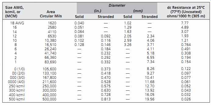
Table 1 Physical Properties of Bare Copper Conductors

Table 2 Allowable Ampacities of Insulated Conductors Rated 0 through 2000
V, 60º to 90ºC (140º to 194ºF), Not More Than Three Current-Carrying Conductors
in Raceway or Cable or Earth (Directly Buried), Based on Ambient Temperature
of 30ºC (86ºF)
8. CONDUCTOR INSULATION AND JACKETS
Most conductors are covered with some type of insulation that provides both electrical isolation and a degree of physical protection. Additional physical shielding, where necessary, is provided by a jacket placed over the insulation. Insulation is rated by voltage. Ordinary building wiring is rated for either 300 or 600 V. Common types of building wire insulation are listed in Table 5 with their associated trade names, code letters, maximum permitted operating temperatures, and special provisions.
9. COPPER AND ALUMINUM CONDUCTORS
Aluminum has an inherent weight advantage over copper, which brings with it lower installation costs. Economy usually lies with copper in small- and medium-sized cable, because weight is not a problem, and the smaller conduit required for the smaller copper conductors generally makes the combined installation cheaper. In larger cable sizes, the aluminum weight advantage offsets the economy of smaller copper size and conduit, and aluminum generally proves less expensive, particularly in many urban areas with high labor costs.
Aluminum and copper both exhibit the low electrical resistivity necessary for a good electrical conductor. There are, however, difficulties inherent in splicing and terminating aluminum. These difficulties-which can be overcome with the use of proper equipment, techniques, and workman ship-stem from aluminum's cold-flow characteristic when under pressure (causing joints to loosen) and aluminum's oxide. This oxide, which forms within minutes on any exposed aluminum surface, is an adhesive, poorly conductive film that must be removed and prevented from reforming if a successful, long-life joint or termination is to be made. If this is not done, the oxide causes a high-resistance joint with excessive heat generation and possible incendiary effects. The oxide problem can be largely overcome by the use of copper-clad aluminum wire, but the cold-flow problem remains. Furthermore, when used in residential branch circuits, aluminum can create problems (even if properly installed initially) when wiring devices are replaced by unskilled homeowners.
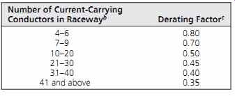
Table 3 Current-Carrying Capacity Derating Factors
As a result of a number of unfortunate incidents, some jurisdictions in the United States have banned the use of aluminum wire in branch circuitry. Heavy feeders are normally installed by experienced and skilled contractors, and the risk of a poor joint is minimized. We recommend that the use of aluminum conductors be restricted to sizes no smaller than No. 4 AWG, and that installation be permitted only by contractors who certify expertise in the specialized techniques involved. Also, local codes and electrical inspectors should be consulted.
All references in this text, including all tables and illustrations, are to
copper conductors. T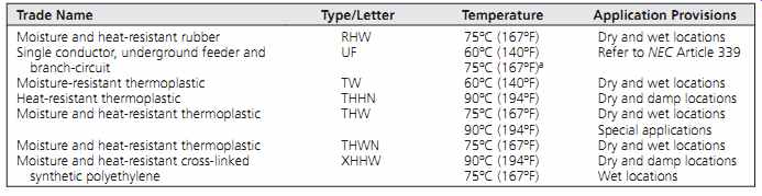 he following sections provide a brief description of the
principal building wire types.
he following sections provide a brief description of the
principal building wire types.
Table 5 Conductor Insulation and Application
10. FLEXIBLE ARMORED CABLE
Among the most common types of exposed wiring is NEC type AC armored cable, commonly known in the smaller sizes by the trade name BX. It is an assembly of insulated wires, bound together and enclosed in a protective armor made of a spiral wound interlocking strip of steel tape (FIGR. 3). The cable is installed with simple U-clamps or staples holding it against beams, walls, and so on. This type of installation is frequently used in residences and in the rewiring of existing buildings. Use of type AC cable is generally restricted to dry locations. For application and installation details and restrictions, see NEC Article 333, "Armored Cable." A similar construction with much broader application (covered in NEC Article 334) is metal clad (MC) cable. This cable may be used exposed or concealed and in cable trays, and, when covered with a moisture-impervious jacket, in wet and out door locations as well (FIGR. 4).
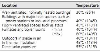
Table 4 Typical Ambient Temperatures
11. NONMETALLIC SHEATHED CABLE (ROMEX)
NEC types NM and NMC, also known by the trade name Romex, are restricted to small building applications-that is, residential and other structures not exceeding three floors above grade (FIGR. 5). The plastic outer jacket, unlike the armor on type AC, makes type NM easier to handle but more vulnerable to physical damage. For application details and restrictions, see NEC Article 336, "Non metallic Sheathed Cable." The typical installation technique is shown in FIGR. 6.
12. CONDUCTORS FOR GENERAL WIRING
Under this heading (Article 310), the NEC lists the wire types that are generally installed in raceways and are referred to by the term building wire. The most common types are listed in Table 5. These wires consist of a copper conductor covered with insulation and, in some instances, with a jacket (FIGR. 7).
13. SPECIAL CABLE TYPES
Although most building wiring is accomplished with plastic-insulated 300- and 600-V conductors of the types described in the preceding sections, some applications require the use of special cables.
These include high-voltage cables, armored cables, corrosion-resistant jacketed cables, underground cables, and so on. The reader is referred to manufacturers' catalogs and the NEC for construction and application details. Service-entrance cables and their installation are discussed in Sections 26.1 and 26.4.
FIGR. 3 Flexible armored cable (NEC type AC, trade name BX). Note the insulating
bushing that is always installed on the end of the armor to protect the wires
from damage from the sharp edges of the cut steel armor. (Courtesy of AFC Cable
Systems.)
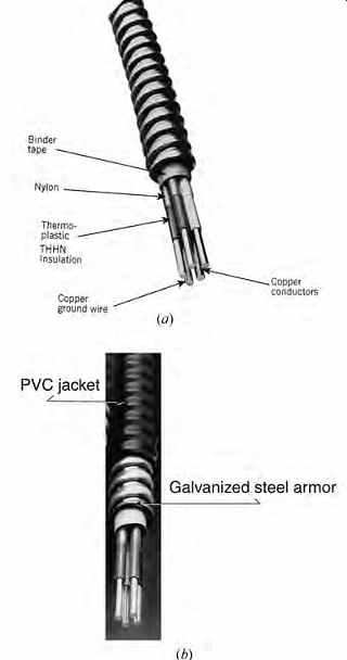
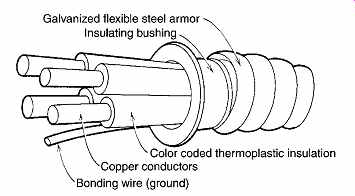
FIGR. 4 (a) Metal-clad cable (NEC type MC, Article 334) with aluminum armor
in lieu of the more common galvanized steel armor. Use is similar to that of
the steel-armored cable, with the weight advantage of aluminum. Conductors
are factory-installed, color-coded, and covered with type THHN insulation and
nylon jacket. Cables of similar construction, using steel armor, are available
for almost all power and control applications. (Courtesy of AFC Cable Systems.)
(b) Jacketed-type MC cable has a wide variety of applications, including in
wet locations, because of its water-impervious outer PVC jacket. Where specifically
indicated by the manufacturer, this cable may be used for direct burial in
earth or installed in concrete. (Courtesy of AFC Cable Systems.)
14. BUSWAY/BUSDUCT/CABLEBUS
A busway (busduct) is an assembly of copper or aluminum bars in a rigid metallic housing (FIGR. 8). Its use is almost always preferable, from an economic viewpoint, in two instances: when it is necessary to carry large amounts of current (power) and when it is necessary to tap onto an electrical power conductor at frequent intervals along its length.
In the case of a heavy current requirement, the alternatives to using busways are to use paralleled sets of round conductors or a single large conductor. Paralleled sets of conductors are almost always more expensive than a busway of similar current capacity because of the high installation cost of multiple conduits. Alternatively, using a single, large-diameter conductor becomes increasingly inefficient as cable size increases because large round conductors require more cross section per ampere of current-carrying capacity than do the flat conductors (busbars) used in busduct (FIGR. 9).
Where many power taps are required along an electric feeder run consisting of cable in conduit, costs become very high because of the large amount of expensive hand labor involved, since a connection must be made to each conductor in the run. The preferable alternative is to use a "plug-in" busway to which connections can be made easily and rap idly with a plug-in device, similar to the insertion of a common plug into a wall receptacle. This has the additional advantage of convenience; connection/disconnection is simply a matter of inserting or withdrawing the plug-in device, whereas cable taps are permanent connections (FIGR. 10).
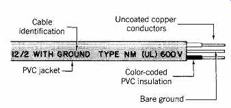
FIGR. 5 Construction of typical NEC type NM cable. The illustrated cable is
a two-conductor, No. 12 AWG with ground, insulated for 600 V. Normally shown
are the manufacturer, cable trade name, and the letters (UL), which indicate
listing of this product by Underwriters Laboratories, Inc. The ground wire
is bare or covered, and the entire cable may be obtained flat (illustrated),
oval, or round.
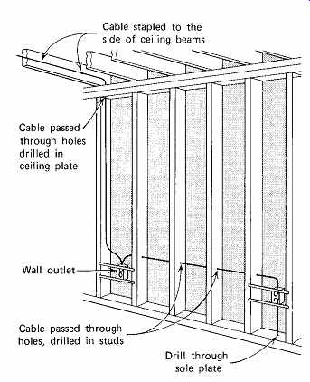
FIGR. 6 Typical wiring technique using types NM (Romex) or AC (BX) in wood
stud construction. With metal stud construction, BX cables are passed through
precut openings in lieu of field-drilled holes. Where cables are exposed to
damage from nails, screws, and other hazards, protective metal cover plates
are required.
For details, see the installation limitations in the NEC.
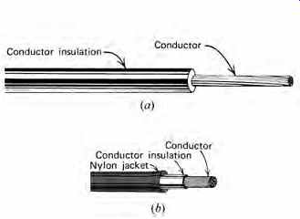
FIGR. 7 (a) Typical construction of unjacketed building wire such as type
THW (see Table 5). (b) The illustrated construction is typical for any nylon-jacketed
cable such as THWN or THHN. (The first three letters indicate the type of insulation,
and the final N indicates the nylon jacket.)
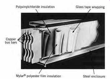
FIGR. 8 Cutaway view showing construction of a typical feeder busduct. This
design is highly compact and rigid, which gives desirable electrical characteristics
as well as the advantage of small size. (Photo courtesy of Siemens Energy and
Automation, Inc.)
A typical application of heavy-duty busduct might be a vertical feeder in a high-rise building connecting the basement switchboard to the penthouse machine room. The same building might also use heavy-duty plug-in busduct as vertical riser(s) with taps feeding individual floors (FIGR. 2). Typical applications for light-duty plug-in busduct (70 to 100 A) could be any machine shop or workshop.
The electrical supply to individual machine tools is made very simply and flexibly with a tap-on device (see FIGR. 10).
Busduct is specified by type, material, number of buses, current capacity, and voltage (e.g., aluminum feeder busduct, 4-wire, 1000 A, 600 V, or copper plug-in busway, 100 A, 3-wire, 600 V). Feeder busduct (no plug-in capability) is available in ratings from 400 to 4000 A. Plug-in busway is available from 30 A for lighting or light-machinery circuits (see Section 15) to 3000 A. A wide variety of fittings and joints is available for all busways to permit easy installation (FIGR. 11). Devices are available for indoor and outdoor application.
Cablebus is similar to ventilated busduct, except that it uses insulated cables instead of busbars. The cables are rigidly mounted in an open space-frame.
The advantage of this construction is that it carries the ampacity rating of its cables in free air, which is much higher than for the same cables in conduit, thus giving a high amperes-per-dollar first-cost figure. Its principal disadvantages are bulkiness and difficulty in making taps.
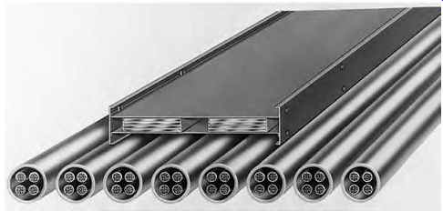
FIGR. 9 Sectional view of a busduct (on top) shows the tight assembly of insulated
conductors within a metal housing. This design, unlike the ventilated type,
can be mounted in any position because heat dissipation is by conduction from
the busbars to the housing. The eight sets of cable shown beneath it have the
same current-carrying capacity as the busduct. (Reproduced by permission of
Square D Company.)
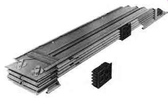
FIGR. 10 Construction of one type of plug-in busduct. Plug-ins are evenly
spaced on alternate sides to facilitate connection of plug-in breakers, switches,
transformers, or cable taps. Housing is of sheet steel with openings for ventilation.
The cover plate is not shown. (Courtesy of Square D Company.)
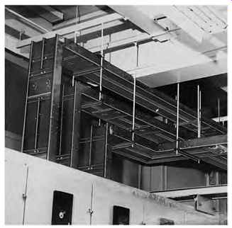
FIGR. 11 Typical installation of compact-design busduct. Note that the individual
busducts are supported by channels hung from the ceiling and that the same
hangers support more than one level of bus. Right-angle turns are easily made
in the same plane (horizontal or vertical) and between vertical and horizontal
planes. (Reproduced by permission of Square D Company.)
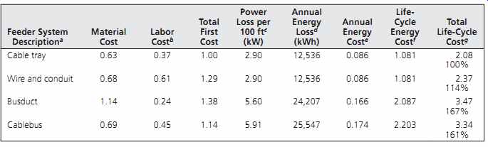
Table 6 Life-Cycle Relative Cost Comparison of 2000-A, 208-V Feeder Installation
An example of the type of economic analysis that should be made when considering an item as fundamental as a heavy-current electrical feeder, is summarized in Table 6, which shows the results of such a study in terms of relative costs. Note that when considering first cost alone, the advantage lies with cable tray (with interlocked armor cables) and cablebus. Adding energy-loss considerations shifts the advantage to cable tray and wire in conduit. No general conclusion should be drawn from Table 6 regarding costs. A change in feeder length, number of taps, hours of operation, energy costs, or any of the other factors can shift the advantage to a different system. The point of the study is to demonstrate that life-cycle costs and first costs often lead to entirely different conclusions and that this type of study is truly required before a rational engineering decision can be made. (Life-cycle cost in this example was taken as the present value of all costs over the installation's life cycle-in this case, 20 years.)
Two additional items are worthy of note:
1. The very factors that yield a lower first cost operate to yield a higher operating cost. The smaller copper sizes in busduct and cablebus, permitted by high-temperature insulation and good ventilation, cause increased power loss because of their higher resistivity.
2. If the heat loss from the busduct or cablebus can be used to advantage, the related energy cost can be credited instead of being considered a total loss, and life-cycle costs can be changed considerably. Conversely, it can also negatively affect the building cooling load.
15. LIGHT-DUTY BUSWAY, FLAT CABLE ASSEMBLIES, AND LIGHTING TRACK
Special prefabricated assemblies that act as light duty (branch circuit) plug-in electrical feeders are widely used because of their simplicity of installation and, more importantly, because of their plug-in mode of connection.
(a) Light-Duty Plug-In Busway
This construction, which may be used either for feeder or branch circuit applications, is covered by the NEC general article on busways, with restrictions when applied as branch circuit wiring. Light duty busways are rated from 20 to 60 A at 300 V, in 2- and 3-wire construction. A somewhat heavier design rated 60 A to 100 A at 600 V is available in 3- and 4-wire construction. Their application is principally for direct connection (with overcurrent protection) of light machinery and industrial lighting.
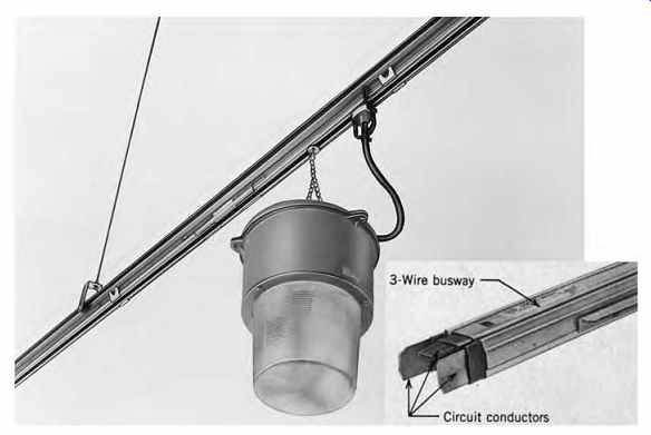
FIGR. 12 Light-duty busway is rated 20-60 A, 300 V, and either 2- or 3-wire.
Power takeoff devices twist into the bus to make contact with the circuit conductors.
Within NEC restrictions of overcurrent protection, this busway may be used
for standard and heavy-duty lighting fixtures and for other electrical devices
such as electrically powered tools. (Courtesy of Siemens Energy and Automation,
Inc.)
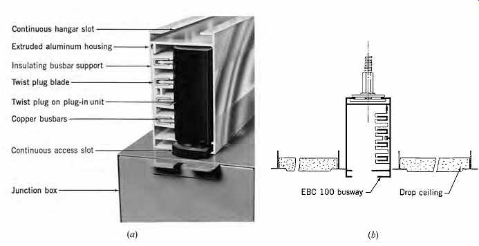
FIGR. 13 (a) Plug-in busway rated 100 A, 3-phase, 4-wire, 600 V measures approximately
2½ in. W × 4½ in. H (64 × 115 mm). The twist-in plug, which is integrally attached
to a connection means (junction box in the illustration), is rated 30 to 100
A, single- or 3 phase, as required. The attached junction box (or receptacle,
circuit breaker, or fuse box) then feeds the utilization device (e.g., heavy
duty lighting or machinery). (b) This bus can also be installed in a hung ceiling.
(Courtesy of Universal Trolley.)
(b) Flat-Cable Assemblies
A specially designed cable (NEC Article 363; Type FC) consisting of two, three, or four No. 10 AWG conductors is field-installed in a rigidly mounted standard 15 8-in. (41 mm) square structural channel. Power-tap devices, installed where required, puncture the insulation of one of the phase conductors and the neutral. Electrical connection is then made to the pigtail wires that extend from the tap devices. This connection can extend directly to the device or to an outlet box with a receptacle, which then acts as a disconnecting means for the electric device being served. In this fashion, lighting fixtures, small motors, unit heaters, and other single-phase, light-duty devices can be served without the necessity of "hard" (conduit and cable) wiring. Figure 14 illustrates similar equipment that is specifically intended to feed industrial lighting fixtures.
(c) Lighting Track
This is a factory-assembled channel with conductors for one to four circuits permanently installed in the track (NEC Article 410-R). Power is taken from the track by special tap-off devices that contact the track's electrified conductors and carry the power to the attached lighting fixture, which can be positioned anywhere along the track. The tracks are generally rated at 20A and, unlike FC cable assemblies, may feed only lighting fixtures. Taps to feed convenience receptacles are not permitted. A typical design is shown in FIGR. 15. An application of track lighting is shown in Fig. 16.9.
16. CABLE TRAY
This system, which is covered in NEC Article 318, is simply a continuous open support for approved cables. When used as a general wiring system, the cables must be self-protected. The advantages of this system are free-air-rated cable ampacities, easy installation and maintenance, and relatively low cost. The disadvantages are bulkiness and accessibility requirements. Cable trays are used primarily in industrial applications.
17. DESIGN CONSIDERATIONS FOR RACEWAY SYSTEMS
The following sections deal with closed wiring race ways, which completes the discussion of raceways.
The details of construction and application are not discussed here because such information is readily available from manufacturers and applicable NEC articles. However, enough material is provided for the reader to become familiar with the types of raceways, their common applications and limitations, and, where applicable, comparative characteristics.
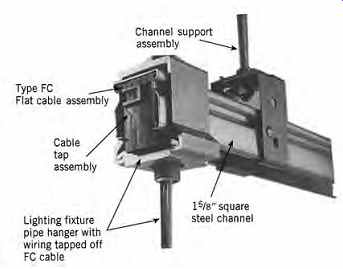
FIGR. 14 A 3-phase, 4-wire flat cable assembly installed in a steel channel
is shown. Taps into the conductors are made by tightening the tap device. Taps
can be made phase-to-ground to give 120 V and phase-to-phase to give 208 V.
(If the cable is connected to a 277/480-V, 3-phase system, then the phase to-ground
and phase-to-phase voltages will be 277 and 480 V, respectively.) After a tap
device is removed, the puncture made by the tap "heals" itself. (Courtesy
of Chan-L-Wire/Wiremold Company.)
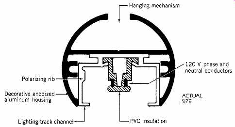
FIGR. 15 Decorative lighting track. The circular housing can be obtained in
a variety of finishes and hanger arrangements. The actual lighting track, shown
full size, is readily available without the housing for direct surface mounting.
Track is also available in a 4-conductor configuration (three 120-V conductors
plus neutral). (Courtesy of Swivelier.)
Although this section covers equipment used primarily in electrical power systems, empty race ways intended for signal, data, and communications wiring (to be provided by others) are normally provided under the electrical section of a construction contract. The function of a raceway in such systems is largely the same as it is for power wiring: protection and isolation of the wiring.
Prior to the widespread use of computers in buildings of all types, raceway space requirements for communication and signal wiring were easily established because such wiring consisted of small telephone cables plus miscellaneous signal and alarm wires. These requirements were easily satisfied with empty conduits or cells in floor race way systems. Today, when virtually every commercial/institutional building uses some type of data-processing equipment, and communication networking is commonplace even in small facilities, raceways for communication cabling have become a major design consideration. They often far exceed in cross-sectional area the space required for power cabling. Their space requirements are sometimes so great that they, like ductwork, have substantial architectural impact and must therefore be considered early in the design process.
Sizing of raceways for power wiring is an exact process (see Section 28.16), based as it is upon maximum permissible temperatures for specific materials in a given environment. This is not so for communication cabling, even when a system's present requirements are known, because of the extremely rapid growth of demand for networking and data interchange. The problem is all the more difficult when designing commercial space for rental to an unknown client. The advisable approach in such cases is either to provide a reasonable amount of floor-level raceway space for main cabling (see Section 24 and 27.25) and to rely on add-on systems such as under-carpet wiring (see Section 29) and surface or ceiling raceways (Section 30) for additional raceway area, or, alternatively, to use a structural system that provides virtually unlimited wiring space (FIGRs. 26 through 32). Because the latter is a major structural/architectural decision, it must be made during the preliminary stages of design. A clear understanding of the owner's project requirements will assist in decision making.
Design considerations for power system race ways are discussed in the following sections and in Section 28. Design of raceways for data and communication system wiring includes the following considerations:
I. Number, type, and location of data-processing terminals.
II. Networking requirements:
A. The type of local area network largely determines the communication media (i.e., coaxial cable, shielded and unshielded wire, and fiber-optic cables), which affects the raceway space requirements. The cable type also determines the type of connectors needed (and their space requirements) and the type of floor outlets used for machine connection.
B. Cable topology (i.e., interconnection arrangements). This item is frequently not within the domain of the architectural designer, although the raceway space availability seriously affects the cabling arrangement and vice versa.
C. Requirement for interconnection of net works and connection to remote networks.
III. Number, location, and characteristics of major peripheral devices, such as mass storage, printing, and plotting.
IV. Location and type of major subsystems, such as computer-aided design/manufacturing spaces.
V. Location of presentation spaces that require interconnection to computer networks.
In view of these highly technical and rapidly changing requirements, engaging the services of a consultant with specialization in this area is suggested.
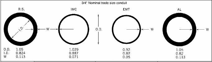
Table 7 Comparative Dimensions and Weights of Metallic Conduit
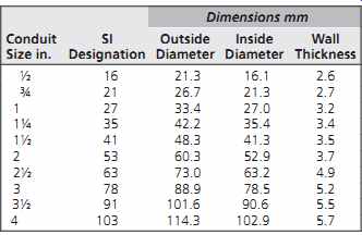
Table 8 SI Equivalents of Rigid Steel Conduit Sizes
18. STEEL CONDUIT
The purpose of conduit is to:
1. Protect the enclosed wiring from mechanical injury and damage from the surrounding atmosphere
2. Provide a grounded metal enclosure for the wiring in order to avoid a shock hazard
3. Provide a system ground path
4. Protect surroundings against a fire hazard as a result of overheating or arcing of the enclosed conductors
5. Support the conductors
For these reasons, the NEC generally requires that all power wiring be enclosed in a rigid metallic corrosion-resistant conduit. To this latter end, steel conduit is manufactured in several types, among which are hot-dip galvanized, sherardized (coated with zinc dust), enameled, and plastic-covered.
There are three types of steel conduit that differ basically only in wall thickness. They are, in order of decreasing weight:
1. Heavy-wall steel conduit, also referred to simply as rigid steel conduit; covered by NEC Article 346
2. Intermediate metal conduit, usually referred to as IMC; covered by NEC Article 345
3. Electric metallic tubing, normally known as EMT or thin-wall conduit; covered by NEC Article 348 The differences are shown in Table 7. Several types of heavy-wall conduit plus EMT are shown in FIGR. 16. The equivalent SI dimensions of conduits are given in Table 8.
Rigid conduit and IMC use the same threaded fittings. As a result of its thin wall, EMT is not threaded; instead, it uses set-screw and pressure fittings. The thinner walls of EMT and IMC yield a larger inside diameter (ID) and, therefore, easier wire pulling. The combination of lower weight and easier wire pulling gives EMT and IMC a distinct labor cost advantage over rigid conduit, which is further enhanced in jobs with a great deal of field bending and handling of conduit. Both, however, have application restrictions, which are detailed in the NEC.
Generally, no conduit smaller than ½-in. (13 mm) nominal trade diameter is used. Ordinary steel pipe may not be used as electric conduit, and all electric steel conduit is distinctively marked as such.
When steel conduit is installed in direct contact with the earth, it is advisable to use the hot-dip galvanized type and to coat the joints with asphaltum.
If the earth is very wet, the entire conduit system should be coated with an appropriate waterproofing compound. Alternatively, a plastic-jacketed conduit can be used.
Conduit is fastened to the building structure in much the same way as piping: with pipe straps and clamps. The vertical load at floor openings is taken with special support clamps. Trapeze mounting is common for conduit banks hung from the ceiling, as in FIGR. 17.
Conduit size depends not only on the maximum permissible temperature of the contained conductors, but also on the number and diameter of the wires that may be drawn into the conduit without injuring the wire. The number and radius of bends in the conduit, as well as its total length, affect the degree of abrasion to the wiring insulation during installation. No wires should be installed until a conduit system has been inspected and approved.
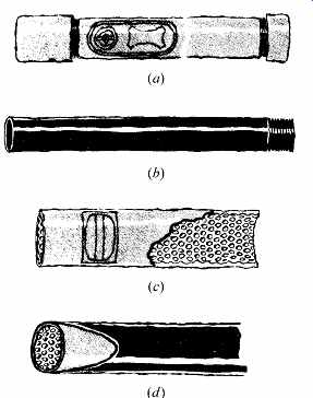
FIGR. 16 Steel conduits: (a) galvanized, heavy wall, rigid, (b) black enameled,
(c) EMT thin wall, (d) plastic-coated conduit for use in highly corrosive atmospheres.
For structural reasons, conduits in concrete slabs are run close to the bottom surface (in the portion of the slab in tension) or near the center. If a large number of conduits must be embedded, it may be necessary to increase the slab thickness. In many instances, the structural slab is covered with a concrete topping, in which conduit may be installed without affecting slab integrity. In all cases, local building codes should be consulted for limitations on embedded conduits. In any event, the top of any conduit shall be at least ¾ in. (19 mm) below the finished floor surface to prevent cracking. When heavy trucking is expected, this allowance should be increased to 1½ in. (38 mm) minimum.
In general, the following rules should be observed and included in all specifications for conduit work in concrete slabs:
1. Conduits shall have an outside diameter (OD) no greater than one-third the slab thickness, as measured at its thinnest point.
2. Conduits running parallel to each other shall be spaced not less than three times the OD of the largest conduit center-to-center.
3. Conduit crossings shall be as close to a right angle as possible.
4. Minimum cover over conduits shall be ¾ in.(19 mm).