AMAZON multi-meters discounts AMAZON oscilloscope discounts
(cont. from part 1)
21. NON-METALLIC CONDUIT
A separate classification of rigid conduit (NEC Article 347) covers raceways that are formed from such materials as fiber, asbestos-cement (not as serious an environmental concern as it might sound), soapstone, rigid polyvinyl chloride (PVC), and high density polyethylene.
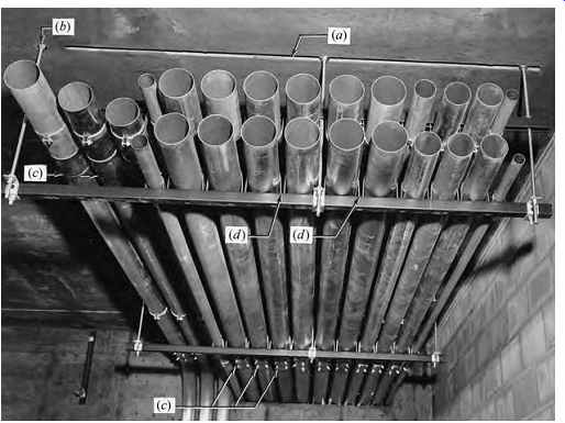
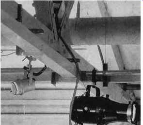
FIGR. 17 Typical overhead conduit bank installation. Note that due to field
conditions the insert (a) for hanger rods was inadequate and an additional
insert (b) was added. This conduit bank uses EMT, which has a pipe-wall thickness
approximately one-third that of heavy-wall rigid conduit. The resulting weight
difference in a large bank such as this is very pronounced. EMT joints are
made with set screw fittings (c). Note how individual conduits are fixed by
clamps to the trapeze channel (d). (Courtesy of Republic Steel Corp.)
For use above ground, such conduit must be flame-retardant, tough, and resistant to heat distortion, sunlight, and low-temperature effects. For use underground, the last two requirements are waived. Generally, nonmetallic conduit may be used without restriction in nonhazardous areas within the physical limitations of the material involved. Thus, plastic conduit has a tempera ture limitation, asbestos-cement has considerable physical strength limitations, and so on. As a result of these limitations, PVC conduit is the material of choice for indoor exposed use, and asbestos- cement, fiber, and PVC plastic for outdoor and underground use. A separate ground wire must be provided because the ground provided by a metallic conduit is absent.
22. SURFACE METAL RACEWAYS (METALLIC AND NONMETALLIC)
These raceways are covered in NEC Article 352.
Surface metal raceways and multi-outlet assemblies may be utilized only in dry, nonhazardous, noncorrosive locations and may generally contain only wiring operating below 300 V. Such raceways are normally installed exposed, in places not subject to physical injury.
The principal applications of surface metal raceways are:
1. Where economy in construction weighs very heavily in favor of surface raceways and where expansion is anticipated (FIGR. 19)
2. Where outlets are required at frequent intervals and where rewiring is required or anticipated (FIGR. 20)
3. Where access to equipment in the raceways is required and/or where necessary due to the nature of the wiring (FIGRs. 19, 21, 22, and 23)
4. Where the extensive and expensive cutting and patching required to "bury" a raceway during rewiring is to be avoided (FIGR. 24)
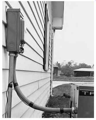
FIGR. 18 This is a particularly good application of liquid tight, flexible
conduit because it provides weatherproofing and mechanical isolation of the
vibration-producing equipment. (Courtesy of Electri-Flex Company.)
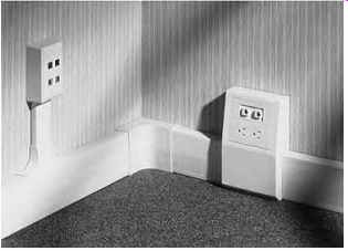
FIGR. 19 Three-section nonmetallic baseboard-type raceway measures 4 in. H
and 1.5 in. D (100 × 38 mm). The three sections are intended for telephone,
power, and data cabling. The junction box on the right protrudes so as not
to lessen the raceway wiring space. It is equipped with vertical dividers to
keep the three types of wiring completely separated. The elevated wall box
on the left contains telephone and data cable outlets and connects only to
the low-voltage portions of the raceway. (Photo courtesy of Hubbell, Inc.)
FIGR. 20 Large-capacity surface metal raceways are particularly useful for wiring in full-access floors (see Section 28) because of the heavy wiring (see wall box) and frequent rewiring. The perforated floor tile in the foreground is used to supply laminar airflow in this clean room at an integrated circuit manufacturer's facility. (Photos courtesy of Walker Systems, A Wiremold Company.)
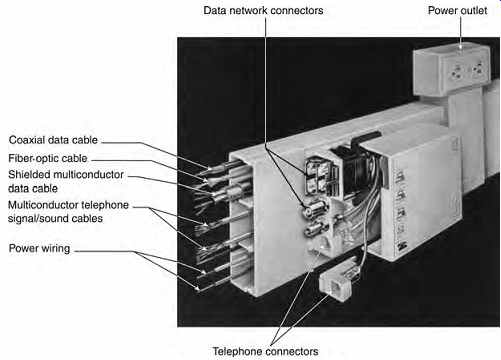
FIGR. 21 Multichannel nonmetallic surface raceway with snap-in connector modules
for data network, signal, and power wiring systems. (Similar metallic raceways
are also available.) The raceway itself measures 4½ in. H × 1 in. D (115 ×
25 mm). The internal dividers are movable or entirely removable, which permits
varying the number and size of the wiring channels. The principal application
of this type of wireway is in commercial occupancies using extensive desktop
data-processing and communication equipment. (Courtesy of Panduit.)
FIGR. 22 The frequent wiring changes required for theater and exhibition lighting
are easily made when the wiring is run in a suspended surface raceway. (Courtesy
of Walker Systems, A Wiremold Company.)
23. OUTLET AND DEVICE BOXES
These boxes are generally of galvanized stamped sheet metal. The most common sizes are the 4-in. (100-mm) square and 4-in. (100-mm) octagonal boxes used for fixtures, junctions, and devices and the 4 × 21 8 in. (100 × 54 mm) box used for single devices where no splicing is required. Box depths vary from 1½ to 3 in. (38 to 76 mm). Nonmetallic boxes may be used with NM and NMC cable and with nonmetallic conduit installations. In wet locations and for outdoor work, cast-iron or cast aluminum boxes are recommended.
An NEC (Article 300-21) requirement that electrical penetrations in fire-rated floors be de signed to maintain fire ratings has spurred electrical manufacturers to produce a line of poke through fittings to meet this need. (This requirement applies also to walls, ceilings, and partitions.) One such design is shown in FIGR. 25. These electrical penetrations have become increasingly prevalent in existing commercial spaces where the expanded need for desktop power and data wiring can be met most economically and rapidly by through-the-floor feeds from accessible wiring in the suspended ceiling plenum below. In addition, these fittings facilitate the electrical wiring relocations so common in rental office occupancies.
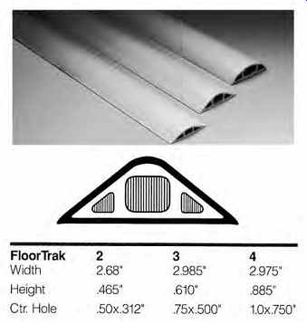
FIGR. 24 Where low-voltage wire and cable cannot be concealed (buried), shallow,
properly shaped floor track can be used.
Such installations should avoid foot-traffic areas where possible to minimize trip hazards. (Courtesy of Hubbell Premise Wiring.)
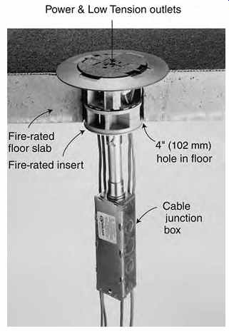
FIGR. 25 Typical poke-through electrical fitting mounts in a 4-in. (100-mm)
hole. It is wired from underneath with the required power, telephone, signal,
and data cables. Power and low-voltage cables are separated as required by
code. Units are available prewired or suitable for field wiring, and adaptable
for varying floor thicknesses. The floor fitting is provided with power, telephone,
and data cable outlets as required for the specific installation. (Courtesy
of Walker, Division of Wiremold.)
FIGR. 23 The basic raceway illustrated is 17 8 in. D × 3 3 16 in. W (48 ×
81 mm). It is shown with a divider installed, permitting use of the top section
for power wiring and the bottom section for low-voltage wiring. Because data
and communication cables are frequently supplied with factory-installed terminations
(as in the photo), a raceway where the cable can be laid in rather than pulled
in is required. Also, terminal strips and other equipment can be installed
in the low-voltage section of these large race ways, making the use of separate
terminal cabinets unnecessary. (Courtesy of Walker Systems, A Wiremold Company.)
24. FLOOR RACEWAYS
In commercial spaces with large open floor areas, it is common practice to place desks and other work stations throughout the space, at considerable distances from permanent walls containing electrical services. Because each workstation in a modern office requires electric power for a computer, desk lamp, and other common equipment plus a telephone line, a computer network connection, and possibly a data outlet, the problem of bringing these services to the workstations with a minimum of exposed wiring is critical. The required outlets can be installed on the floor adjacent to or under the workstations or, if partial-height partitions are used, within these partitions.
To bring the various electrical and communication services to the user, in the absence of any sort of overall floor raceway system, the installing contractor has one of four choices:
1. Channel the floor and install a conduit in the channel, connecting it to the nearest wall out let. Patch the chased portion of the floor.
2. Install a surface floor raceway. The usefulness of this technique is very limited because it presents a tripping hazard and problems with routine floor cleaning.
3. Drill through the floor twice and connect the new outlet to a nearby existing floor or wall outlet via a conduit on the underside of the floor slab. Floor penetrations must be fireproof.
4. Drill through the floor and run a conduit in or on the ceiling below. When using this technique, special poke-through fittings are avail able that restore the fire rating of the slab (see FIGR. 25). These fittings are designed to carry all the electric services normally required at a workstation. They can then be connected to a single-location multiservice floor outlet group, as in FIGR. 25, or used to wire the partitions in a workstation, as in FIGR. 26.
All four of these methods have serious disadvantages; method 1 is labor intensive, method 2 is unsightly and presents a safety hazard, methods 3 and 4 disturb the occupants below, and all four methods are generally inflexible and therefore unsuitable for spaces where reasonable changes in wiring and workstation location are anticipated. For these reasons, overall-access in-floor and underfloor raceway systems were developed and are widely used in high-grade commercial and institutional spaces.
The NEC recognizes three types of in-floor raceways:
Underfloor raceways-Article 354 Cellular metal floor raceways-Article 356 Cellular concrete floor raceways-Article 358 All three types are applicable to all types of structures, and none may be used in corrosive or hazardous areas. The fundamental difference between them is that underfloor raceways are added on to the structure, whereas cellular floor raceways are part of the structure itself-and therefore have a pronounced effect on architectural coordination. (Underfloor duct systems antedate poke through fittings, which are a relatively recent development.)
25. UNDERFLOOR DUCT
These raceways may be installed beneath or flush with the floor. They find their widest application in office spaces because their use permits placement of power, data, and signal outlets close to desks and other furniture, regardless of spatial layout. Under floor duct systems were widely employed until the introduction of what may be called over-the-ceiling ducts (in contrast to under-the-floor ducts) and flat-cable under-carpet wiring. These systems are discussed in Section 29 and 30. The reason that alternative systems were developed is simply economic: underfloor duct systems are expensive and, because they are inflexible, being literally cast in concrete, they are frequently underutilized in one area while being inadequate in another. Before discussing the relative merits of systems, however, an understanding of what underfloor duct systems are and how they are assembled and utilized is necessary.
An underfloor duct system is simply an arrangement of parallel rectangular metal or heavy plastic raceways laid on the structural slab and covered with concrete fill. Access to the wiring in these distribution ducts is via inserts that connect to openings in the ducts and terminate in floor fit tings for both power and signal/data wiring. Cable feeds to the distribution ducts are supplied by a second set of rectangular raceways called feeder ducts, usually laid at right angles to the distribution ducts.
In a single-level underfloor duct system, the distribution and feeder ducts are on the same level,
and the interwiring between them is accomplished in junction boxes. The advantage of a single-level system is shallow concrete fill, normally 2½ to 3 in. (64 to 76 mm). The limiting constraint of a single level system is the junction box, which becomes more complex and multisectioned with an increasing number of ducts and wires. Newer systems utilize a one-piece triple-cell duct for both distribution and feeder ducts, with factory set inserts every 24 in. (610 mm) that straddle all three cells at once (FIGR. 27). By placing distribution ducts on 5-ft (1.5-m) centers with adequate crosswise feeder ducts and utilizing large flat junction boxes, a cost-effective installation adequate for all but the heaviest wiring demands can be assembled.
For demanding areas, distribution ducts can be arranged to feed under-carpet cables (see Section 29).

FIGR. 26 Typical application of a poke-through fitting to provide power, telephone,
and data service to a modern workstation. This drawing shows the electrical
services being tapped at junction boxes in a hung ceiling conduit system on
the floor below. The ceiling wiring system can also be a raceway network in
lieu of the hard-wiring shown here. (From AIA: Ramsey/Sleeper, Architectural
Graphic Standards, 11th ed. 2007. Reprinted by permission of John Wiley & Sons.)
Because the initial cost of a full underfloor system is high, an alternative arrangement utilizes only feeder ducts on approximately 25-ft (7.6-m) centers, with flat (under-carpet) cable box connectors spaced approximately every 20 ft (6.1 m) along the feeder ducts. The low-tension (voltage) portion of this system relies completely on flat telephone and data transmission cables, including fiber-optic (FO) cables.
Because these cables are generally precut and factory terminated, the system requirements must be care fully analyzed (see Section 29) before committing to a complete under-carpet wiring system.
A two-level underfloor duct system is essentially the same as a single-level system except that the distribution ducts and feeder ducts are on different levels (FIGR. 28). This arrangement has the advantages of simplifying junction boxes and of giving the system unlimited feeder capacity, but the distinct disadvantage of requiring a mini mum of 35 8 in. (92 mm) of concrete fill. This additional slab thickness can frequently be avoided by depressing part of the slab to accommodate feeder ducts run under the distribution ducts, as shown in FIGR. 29.
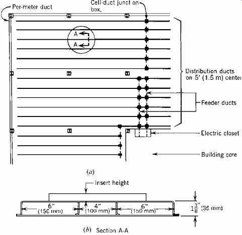
FIGR. 27 Details of a single-level underfloor duct system utilizing three-section
cell duct for both distribution and feeder ducts.
(a) Portion of a typical large open floor space in a commercial facility. Distribution ducts may be placed as close as on 5-ft (1.5-m) centers to satisfy dense desk spacing. (b) Three-cell distribution duct utilizes a 4-in. (100-mm)-wide center cell (4.9 in. 2 [3160 mm^2]) for power and either 3-in. (75-mm)-wide (3.7 in. 2 [2386 mm^2]) or 6-in. (150-mm)-wide (7.4 in.2 [4773 mm^2]) outer cells for signal and data cabling. Minimum concrete fill depth is 2½ in. (64 mm), resulting in a minimum 1-in. (25-mm) cover over the distribution ducts. Service fittings are flush with the floor. (Courtesy of Square D Company.)
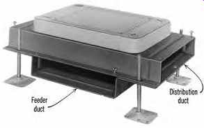
FIGR. 28 Typical two-level junction box demonstrates the simplicity of the
two-level system. (Courtesy of Square D Company.) FIGR. 29 Setting a two-level
underfloor duct system. To avoid thickening the fill, a depression in the slab
can accept feeder ducts. Ducts would be run near the bay center to avoid the
negative steel required of joists near columns.
A typical two-level system is illustrated in FIGR. 30. Here, the feeder ducts run above the distribution ducts and intersect at a specially constructed junction fitting, into which the distribution ducts partially recess in order to reduce overall system height. The required concrete fill is either 3 or 4 in. (75 or 100 mm), depending upon the depth of the distribution cells (2 or 3 in. [50 or 75 mm]).
In all underfloor duct systems, the principal cable capacity bottleneck is usually the supply point to the feeder ducts. One solution to this problem uses a special feed arrangement at panels (FIGR. 31). Another possibility is to subdivide large floor areas, supplying each via a system of multiple feed points arranged in closets or at wall panels. In such systems, care must be taken to ensure sufficient inter connection capacity between feed points because data networks are not only floor-wide but frequently building wide.
Underfloor ducts may be cast into the structural slab in lieu of being installed in fill or topping, but the slab must be designed to accommodate them. The use of a fill or topping on the structural slab for an underfloor duct installation has these advantages:
1. Ducts can be run in any direction, without conflict with structural elements.
FIGR. 30 Modified two-level underfloor duct system requires 3 in. (75 mm) of concrete fill for 2-in. (50-mm)-high ducts and 4 in. (100 mm) of fill for 3-in. (75-mm)-high ducts. Preset inserts straddle all three cells and provide two duplex power receptacles plus connection to both low-voltage cells. Distribution ducts recess into feeder-header ducts at junction boxes to reduce the overall height. See insert. (Courtesy of Walker Systems, A Wiremold Company.)
2. Finishing is simplified.
3. Coordination is simplified.
4. Formwork and construction sequence are simplified.
The disadvantages are:
1. Additional concrete increases costs directly by increasing the weight of the structure. This is particularly expensive in seismic designs.
2. The building height may be increased.
In retrofit jobs where underfloor duct is selected rather than one of the other floor or ceiling race way systems, the ducts will be placed in a new (added) floor fill.
In conclusion, some general comments on the application of underfloor duct systems are in order.
Underfloor duct systems are expensive. They can add 50% to the building's electric system cost, with out consideration of the other construction costs involved. To justify their use, therefore, a building should meet these criteria:
1. There are open floor areas, with a requirement for outlets at locations removed from walls and partitions.
2. An under-carpet wiring system is inapplicable.
3. Outlets from ceiling systems are unacceptable.
4. Frequent rearrangement of furniture and other items requiring electrical and signal service is anticipated.
The facilities that may meet these criteria include many office buildings, museums, galleries (and other display-case spaces), high-cost merchandising areas, and selected areas in industrial facilities.
Bear in mind that even in high-cost office construction, underfloor duct systems are difficult to justify economically unless the spatial/furniture layout will be likely to change. In doubtful cases, alternate arrangements can be planned and an intelligent choice made after costs and the impact on the building structure are studied.
26. CELLULAR METAL FLOOR RACEWAY
The underfloor duct system described previously is best applied to rectilinear arrangements. More free-flowing arrangements, such as those found in office landscaping layouts, require a fully accessible floor-if the floor is to be used for electrification. This may be provided by a cellular (metal) floor that is an integrated structural/electrical system. The floor can be partially or completely electrified. One of the many available structural element approaches is shown in FIGR. 32.
The cellular floor is part of the structural system and is designed accordingly. Electrical wiring is fed into the cells from header ducts and/or trenches that run perpendicular to the floor cells and constitute a system of underfloor ducts in themselves. The header ducts in turn are fed from electric panels and signal data-transmission and telephone cabinets in much the same manner as underfloor ducts are fed.
Three types of wiring systems generally run in separate floor cells and header ducts-electric power, data-transmission wiring, and telephone and signal systems. The last two may be combined in a single cell only if the signal system voltage and power level are low and the local telephone company approves. A complete range of outlets and fit tings is available.
27. PRECAST CELLULAR CONCRETE FLOOR RACEWAYS
This structural concrete system is similar to a cellular metal floor in application and has the same advantages: large capacity, versatility in that each cell is a potential raceway, and flexibility in outlet placement and movement. Here too, as with metal cell constructions, the first cost is higher than that of standard underfloor duct installation, although the life-cycle cost is frequently lower, depending upon space use and reconfigurations.
A cell is defined in NEC Article 358 as a "single, enclosed, tubular space in a floor made of precast cellular concrete slabs, the direction of the cell being parallel to the direction of the floor member." A feed for these cells is provided, as with metal cellular floor construction, by header ducts. Although header ducts are normally installed in concrete fill above the hollow-core structural slab, a header arrangement with feed from the ceiling below is also entirely practical. As with a metallic cellular floor, the cells can be used for air distribution and even for piping, although these elements are generally installed in a hung ceiling.
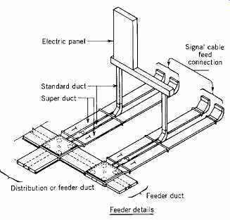
FIGR. 31 Due to the large capacity of both distribution ducts and feeder ducts,
central cable feed points such as at electric closets can cause bottlenecks.
Illustrated is one possible solution, consisting of a double-duct feed arrangement.
Signal cable would feed in from cable boxes (not shown). P is a power duct,
T a signal duct. (Diagrams courtesy of Square D Company.)
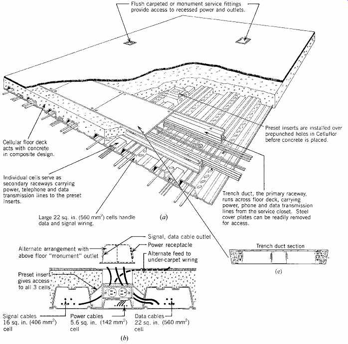
FIGR. 32 (a) One of many designs for electrified cellular floors. The floor
cells are available in many designs, depending primarily upon the structural
requirements. The trench (illustrated in c) that straddles the cells provides
the electrical feeds through precut holes in the cells.
The trench itself is completely accessible from the top and, when opened, exposes all the wiring and the cells below. (b) Activated preset insert. Note that the insert straddles the center (power) cell and provides access to the two adjoining low-voltage wiring cells. Power and signal wiring are completely separated at all times by metal barriers. If desired, a standard surface "monument" fitting can be mounted on the floor, or a connection can be made to under-carpet cables in lieu of the flush plate shown. When an insert is to be deactivated, the flush cover plate is simply replaced with a blank plate. (c) Section through a trench duct, which acts as a feeder for distribution ducts. The trench is available with or without bottom, in any required height, in widths from 9 to 36 in. (230 to 915 mm), and one, two, or three compartments, depending upon floor cell design and cabling requirements. (Courtesy of Walker Systems, A Wiremold Company.)
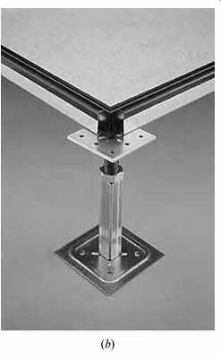
28. FULL-ACCESS FLOOR
This construction is applicable to spaces with very heavy cabling requirements, particularly if frequent re-cabling and reconnection are required. It provides rapid and complete access to an under floor plenum. The system was originally developed for data-processing areas that require large, fully accessible cable spaces and large quantities of conditioned air. The solution to both of these requirements is an infinite-access floor, usually constructed of lightweight die-cast aluminum panels supported on a network of adjustable steel or aluminum pedestals. Panels are available from 18 × 18 in. to 36 × 36 in. (457 × 457 mm to 915 × 915 mm), and floor depth is normally 12 to 24 in. (305 to 610 mm), although taller pedestals are available. The subfloor space thus created can be used for cabling and also to carry conditioned air either in ducts or by using the entire space as an air plenum. (In the latter case, the wire and cable must be suitable for air plenum use; see Fig. 20.) The construction is usually fireproof. Sufficient floor-to-floor height is necessary to accommodate the raised floor. This approach to electrical distribution may coordinate quite well with an underfloor air distribution system (UFAD)-see Section 10.
Where air requirements are limited or non existent and the floor is intended primarily for cabling, pedestals as short as 6 in. (152 mm) can be used, thus reducing ceiling height problems (FIGR. 33). In such access floor spaces, use of multiservice distribution modules and modular wiring avoids cable tangles and reduces labor costs significantly (FIGRs. 33 to 36).
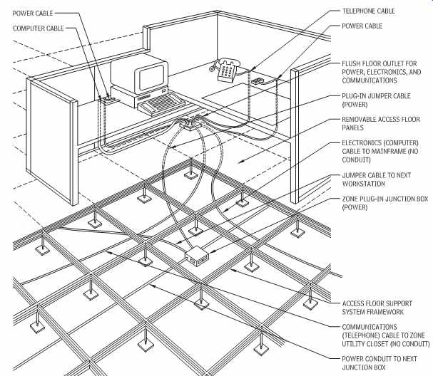
FIGR. 33 Pictorial representation of a full-access floor designed to provide
complete electrical, data, and signal services to a modern workstation layout.
The infinite access and unlimited space are ideal for heavily wired, rapidly
changing workstation arrangements. (From AIA: Ramsey/Sleeper, Architectural
Graphic Standards, 11th ed. 2007. Reprinted by permission of John Wiley & Sons.)
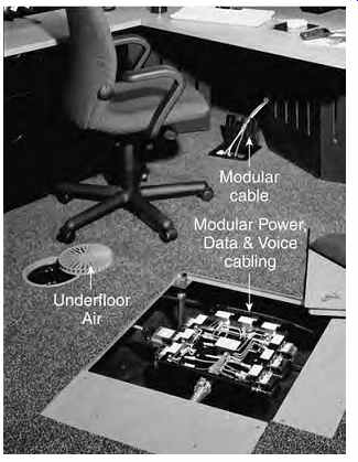
FIGR. 34 Full-access floors provide infinite access to the myriad cables used
in a modern commercial office. The modular wiring, using snap-on connectors
and preassembled junction boxes, drastically reduces the labor cost of installation
and frequent cabling changes (see FIGR. 36a). (Photo courtesy of Tate Access
Floors, Inc.)
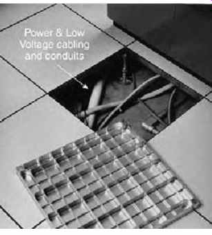
FIGR. 35 Reinforced nonferrous (aluminum) floors are used frequently in hi-tech
applications requiring the large wiring capacity and convenience of full-access
floors. Floor construction can be stringerless, as illustrated, or with stringers,
as in FIGR. 36b. (Photo courtesy of Tate Access Floors, Inc.)
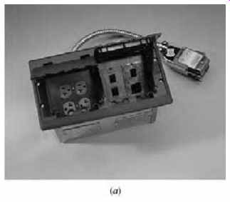
FIGR. 36 (a) Typical power/low-voltage floor box for use with a full-access
floor. (b) Steel-bolted stringer support for access floor panels. Many stringer
and stringerless designs are available. (Photos
courtesy of Tate Access Floors, Inc.)
29. UNDER-CARPET WIRING SYSTEM
This system, which is covered in NEC Article 328, was originally developed as both an inexpensive alternative to an underfloor or cellular floor system and as a means for providing a flexible floor-level branch circuit wiring system. Essentially, the system consists of a factory-assembled flat cable (NEC type FCC), approved for floor installation only under carpet squares, plus the accessories necessary for connection to 120-V power outlets. The cable itself consists of three or more flat copper conductors, placed edge to edge and enclosed in an insulating material (FIGR. 37). The entire assembly is covered with a grounded metal shield, which, like a metal conduit, provides both physical protection and a continuous electrical ground path. In addition, a bottom shield is required, which is usually heavy PVC or metal.
The cable, when properly installed on a hard, flat surface, is approximately 0.03 in. (0.8 mm) high, and thus essentially undetectable when covered with carpet. Because carpet squares are designed to be readily removable, the entire system can be repositioned to meet changing furniture layout requirements with a minimum of disruption and no structural work. The cable is designed to carry normal physical loads such as office traffic and furniture placement without affecting its electrical performance.
The attractiveness and simplicity of the system led to the development of similarly designed flat, low-tension (voltage) cables for signal and communication wiring (FIGR. 38) and, more recently, both electrical and fiber-optic cables and accessories for data transmission. Manufacturers also offer a complete line of junction fittings, connectors, adapters, and receptacles (FIGR. 39).
The problems inherent in this type of on-the floor wiring system, such as cable crossings, splicing, interfacing with round cable systems, interconnections at floor boxes and fittings, feed connections from cabinets, underfloor ducts, floor cells, and through-the-floor fittings, have all been solved by a full line of manufactured devices designed for specific situations.
Because under-carpet wiring systems are separate and distinct from wire and conduit systems, they, like underfloor duct systems, are usually shown on a separate electrical plan. A small plan typical of this type is shown in FIGR. 40. Figures 41 and 42 are photographs of essential portions of such an installation. Note that a complex system such as that shown in FIGR. 42 requires recessing a floor box into the slab, which to an extent contradicts the essential simplicity and flexibility of an under-carpet system. Although these systems, at least in their simplest form, are particularly applicable to retrofit work, their low cost, combined with the inherent advantages of a flexible FIGR. 37 Schematic section through one design of NEC type FCC under-carpet cable. The copper conductors illustrated are the equivalent of No. 12 AWG. The PVC acts as insulation, and the polyester as both insulation and physical protection. All designs require a metallic top shield and a metallic or nonmetallic bottom shield for physical protection.
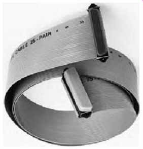
FIGR. 38 Pre-terminated 25-pair under-carpet telephone cable.
These cables are commercially available in lengths from 5 to 50 ft (1.5 to 15 m) in 5-ft. (1.5-m) increments. (Reprinted with permission of AMP.)
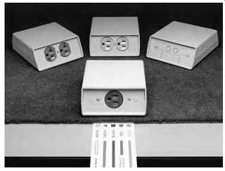
FIGR. 39 Typical components of an under-carpet wiring system. The under-carpet
FCC power cable is shown without the metallic top shield required in actual
installation. It is a color-coded, five-conductor cable (neutral, equipment
ground, and three circuit conductors or two circuit conductors and an isolated
ground conductor). The floor outlets shown are front, single-power outlet;
rear (left to right), duplex power outlet (one of which has isolated ground);
standard duplex power outlet; and combination data cable, communications, and
telephone outlet. (Courtesy of Hubbell, Inc.) floor-level wiring system, particularly
in open office areas, has made them a widely used first choice in new construction
as well.
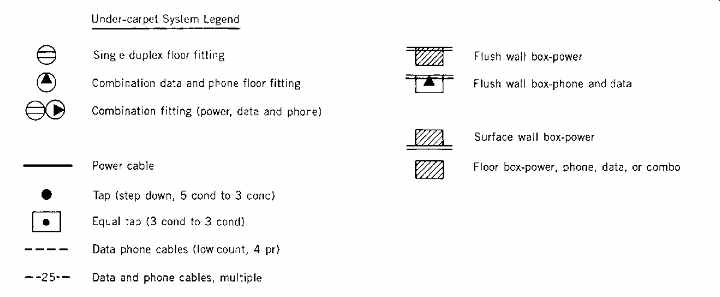
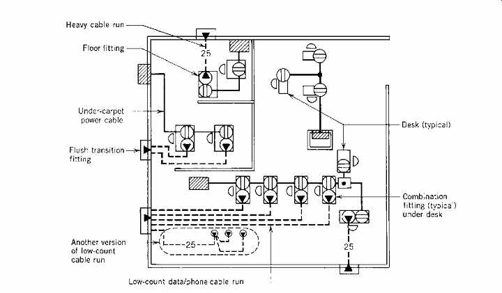
FIGR. 40 Typical layout of under-carpet power and low-voltage/data cabling
for a small office. A power, phone, and data cable connection on the floor
is provided under or immediately adjacent to each desk . (Reproduced with permission
of AMP.)
FIGR. 42 Four service floor-junction boxes handle under-carpet power, telephone, low-voltage electric, and FO cables. The floor box measures approximately 14 in. (356 mm) square and 2 in. (50 mm) deep. It can accommodate up to four 3-phase power circuits, eight 25-pair telephone/data cables, 24 coaxial cables, or, as illustrated, a mixture of cable types. (Reprinted with permission of AMP.)
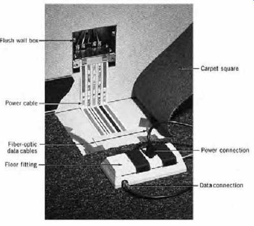
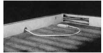
FIGR. 41 Under-carpet flat power cables connect to round supply cables in
a flush wall box and then extend to a combination power/low-voltage/data floor
fitting. Data cables are connected to the combination floor fitting from their
system boxes, either individually or via other floor fittings. (Photo courtesy
of Walker Systems, A Wiremold Company.)
30. CEILING RACEWAYS AND MANUFACTURED WIRING SYSTEMS
The need for flexibility in a facility's electrical system coupled with the high cost of underfloor electrical raceway systems encouraged the development of equivalent over-the-ceiling systems. These systems are actually more flexible than their underfloor counterparts because they energize lighting, pro vide power and telephone facilities, and even supply outlets for the floor above, in addition to permitting very rapid layout changes at low cost. This last characteristic is particularly desirable in stores where frequent display changes necessitate corresponding electrical facility changes. Beyond the extreme flexibility made possible by the ceiling raceway system, it has the additional advantage that the system itself, not being cast in concrete like its underfloor counterpart, can be altered at will. Thus, not only layout changes (as mentioned previously) but also changes in space function can readily be accommodated. This is a particularly important characteristic in merchandising and educational facilities, where space function can be repeatedly changed during the course of a building's life.
Details vary among manufacturers but the systems are essentially the same and, in principle, resemble underfloor systems. A typical system is constructed of metallic or nonmetallic surface type raceways arranged in a tree formation (i.e., large trunk [header] raceways feed multiple smaller branch [distribution] raceways, and so on). The raceways are hung in the ceiling plenum from the concrete slab above. The hung ceiling must consist of lift-out panels because this type of wiring system is not permitted in spaces rendered inaccessible by the building structure. Header ducts (large area raceways) are fed from electrical panels and from signal, data, and telephone cabinets in the electrical and low-voltage wiring service closets, respectively.
Data headers are normally larger than the power header and can carry other low-voltage, low-power signal wiring as well. Distribution ducts (laterals) tap onto the headers. These laterals act as sub-distribution raceways, feeding lighting fixtures and data, signal, telephone, and power outlets on the same floor and, via poke-through fittings, outlets on the floor above.
The standard method for extending wiring from the ceiling plenum raceways to floor-level or desk-level signal and power outlets uses vertical multi-section raceways fed from the top (see FIGR. 43). These service poles are available in a large variety of designs, finishes, and cross-sectional raceway areas and are easily installed in almost any location. They may be prewired and usually contain several power outlets, a telephone connection, and possibly data cable outlets. The result in a hung-ceiling office area or an exposed ceiling slab area (FIGRs. 44 and 45) is certainly less elegant than that of a floor-level wiring system, but for most users it is satisfactory, and its low cost compared to any type of floor-duct system is a prime redeeming feature.
When electrical connections to poles, lighting fixtures, receptacles, and communication/data outlets are made with hard wiring, considerable field labor is required, with a corresponding high cost. Furthermore, the relative permanence of such wiring lessens the inherent flexibility of the race way system. To solve both problems, a number of manufacturers have developed a line of modular branch-circuit wiring elements. These, covered in NEC Article 604 under the very logical name manufactured wiring systems, consist of metal-clad or armored cable sets terminating in polarized plugs.
The polarization prevents accidental interconnection of low-voltage, 120- and 277-V systems.
Ceiling raceways can be equipped with matching receptacles, and connection to fixtures, poles, and other devices becomes a simple matter of plug insertion.
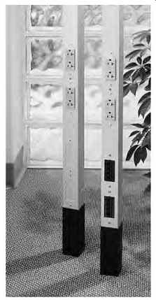
FIGR. 43 Typical floor-to-ceiling electrical/communication raceway poles.
Units are available in a wide variety of shapes, sizes, and cross-sectional
configurations in aluminum and steel. (Courtesy of Hubbell Premise Wiring.)
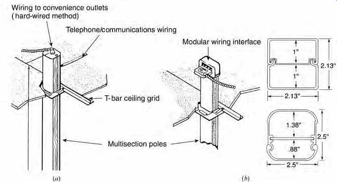
FIGR. 44 (a) Poles are fed at the top from the suspended ceiling or from exposed
ceiling raceways. These feeds can be either conventional hard-wired or modular
(plug-in), as shown. Modular connectors are used for power and low-voltage
(telephone, communication, data) wiring. (b) Two of the many cross-sectional
configurations available are illustrated. Other designs divide the pole into
three sections to suit the specific application. (Courtesy of Hubbell Premise
Wiring.)
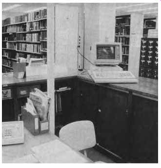
FIGR. 45 Power poles extend down from the ceiling to any desired height. In
this library, power is required above the base cabinets, and the power pole
is easily arranged to supply it. (Courtesy of Wiremold Company.)
The result is a wiring system of extreme flexibility in which even extensive changes can be made very rapidly with minimal disruption and virtually no mess. Manufactured wiring systems are only permitted in accessible areas, for logical reasons. They are also applicable to access floor spaces, as seen in FIGRs. 33 to 36. The additional cost of manufactured wiring elements is frequently offset by the labor savings, even upon initial installation and certainly after one or two field changes. Cable sets are available for power (120 V and 277 V), telephone, and all types of low-voltage signal equipment. The cables must be approved for use in conditioned-air plenums and suspended ceilings.
To take full advantage of the potential labor cost savings inherent in the system, field labor must be minimized. This is accomplished by factory-equipping all utilization equipment, including lighting fixtures, with appropriate plug-in connectors.

FIGR. 46 Manufactured modular wiring assemblies are used for tap connections
to feed ceiling lighting fixtures or any other ceiling connection, as well
as a complete range of junction, switching, tap, and poke-through units. (Courtesy
of Walker Systems, A Wiremold Company.)
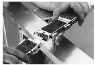
FIGR. 47 Manufactured modular wiring connectors simplify installation and
reduce labor costs initially and during any subsequent rearrangements. (Courtesy
of AFC Cable Systems.)
Prev. | Next
Home Similar
articles top
of page